
With the basic fuselage structure complete it was time to start equipping it.
This was mainly a process of installing the subassemblies that I’d already completed such as the instrument panel, fuel tanks and such. However a number of smaller items did require building up first.
The control column and rudder bar were pretty straight forward. Or should’ve been. For some reason the varnish on the rudder bar refused to dry. It took a week sat on the top of a radiator before it was hard enough to handle. No idea what went wrong there.

The cockpit as presented in the kit is actually lacking in quite a bit of the fine detail. Not least is the fact that no fuel lines are provided. They were relatively easy to add though and there are plenty of reference pictures and diagrams on the net to work out what should be connected to what. I used lacquered soft copper wire of 0.75mm diameter to simulate the pipes.
I also modified the kit’s white metal casting of the throttle to amend the shape of it and add the linkage to the mixture control. Another addition was the inclusion of a small in-line fuel tap between the mixture control valve and the fuel pipe going forward to the engine. You can see all of these changes in the picture below.
The fuel tap was made out of brass pipe and rod hand filed to shape then polished up with emery paper and metal polish. The whole thing was then given a car wax coating as this delays oxidation for a surprisingly long time.

One significant change that I did make at this stage was to scrap the fuel gauge provided in the kit. To my mind it is simply oversize and impossible to fit in the correct location without it fouling the plywood sides of the cockpit. Running realistic fuel lines to it is right out.
To overcome this I made a replacement about 90% of the size out of brass and glass. Sourcing the glass was particularly difficult. You can get the right size easy enough, but with minimum order quantities that meant I would have had enough to do 1000 of these models.
In the end I gave up and compromised on some tube that is slightly undersize, but I could actually get free. The installed gauge is shown below.

The original fuel guage provided in the kit is shown below, prior to it being dumped.

In parallel with the above I also installed the fuel tanks which is pretty straight forward (and necessary to complete the fuel pipe runs).

Don’t rely on these pictures for details on the fuel pipe runs though. In particular, the obvious one you can see above goes the wrong side of the frame vertical. It should be inboard not outboard and was corrected (aka scrapped and remade) after this shot was taken.
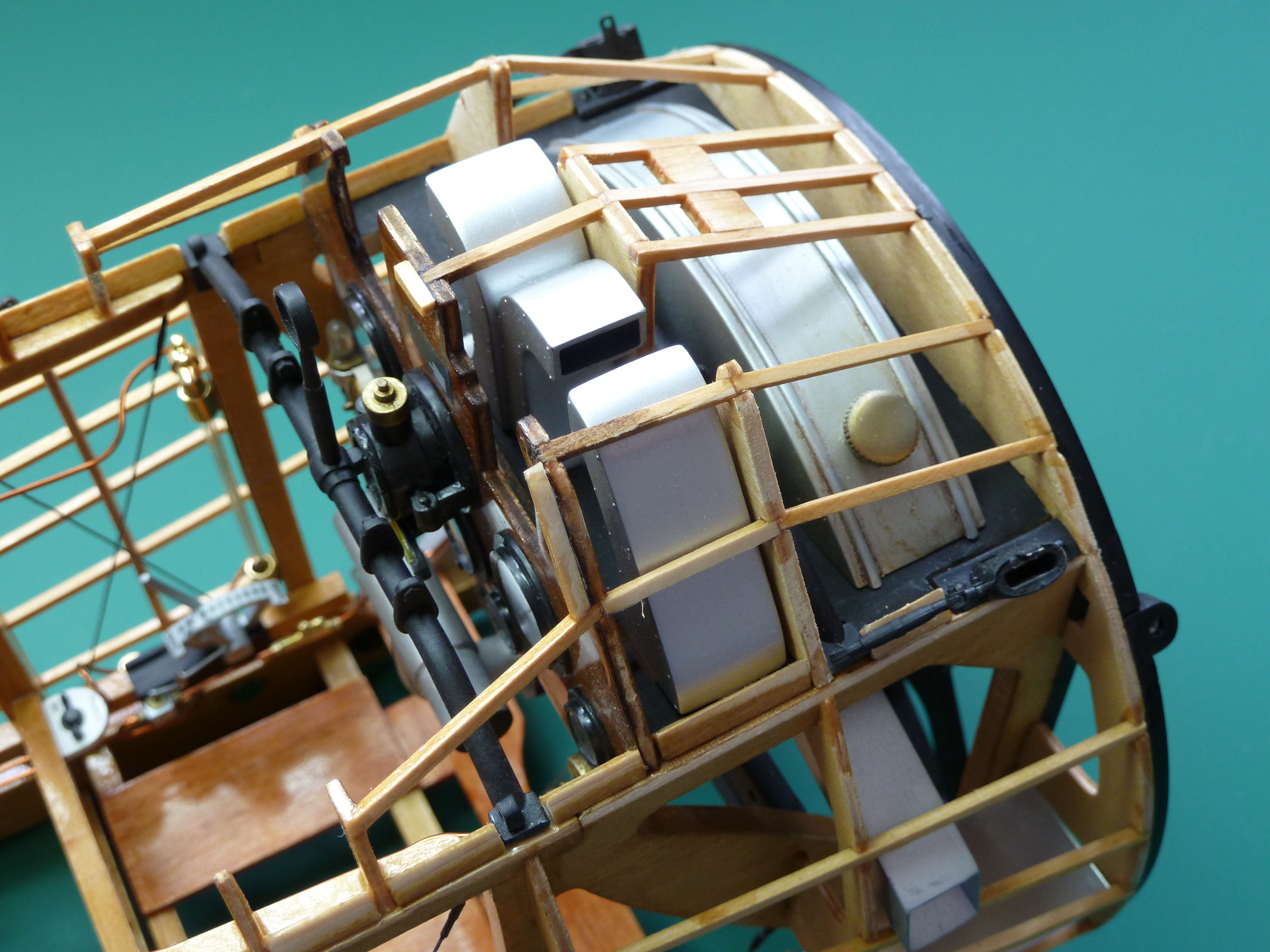
With the main cockpit done (excluding seat and lap strap) I moved on to fitting the ammunition boxes, chutes and castor oil tank. All of these have been truncated in height in the kit to accommodate an electric motor below. Once the model is fully built the subterfuge isn’t obvious so I built it as is, with the exception of painting the false platform they sit on black.
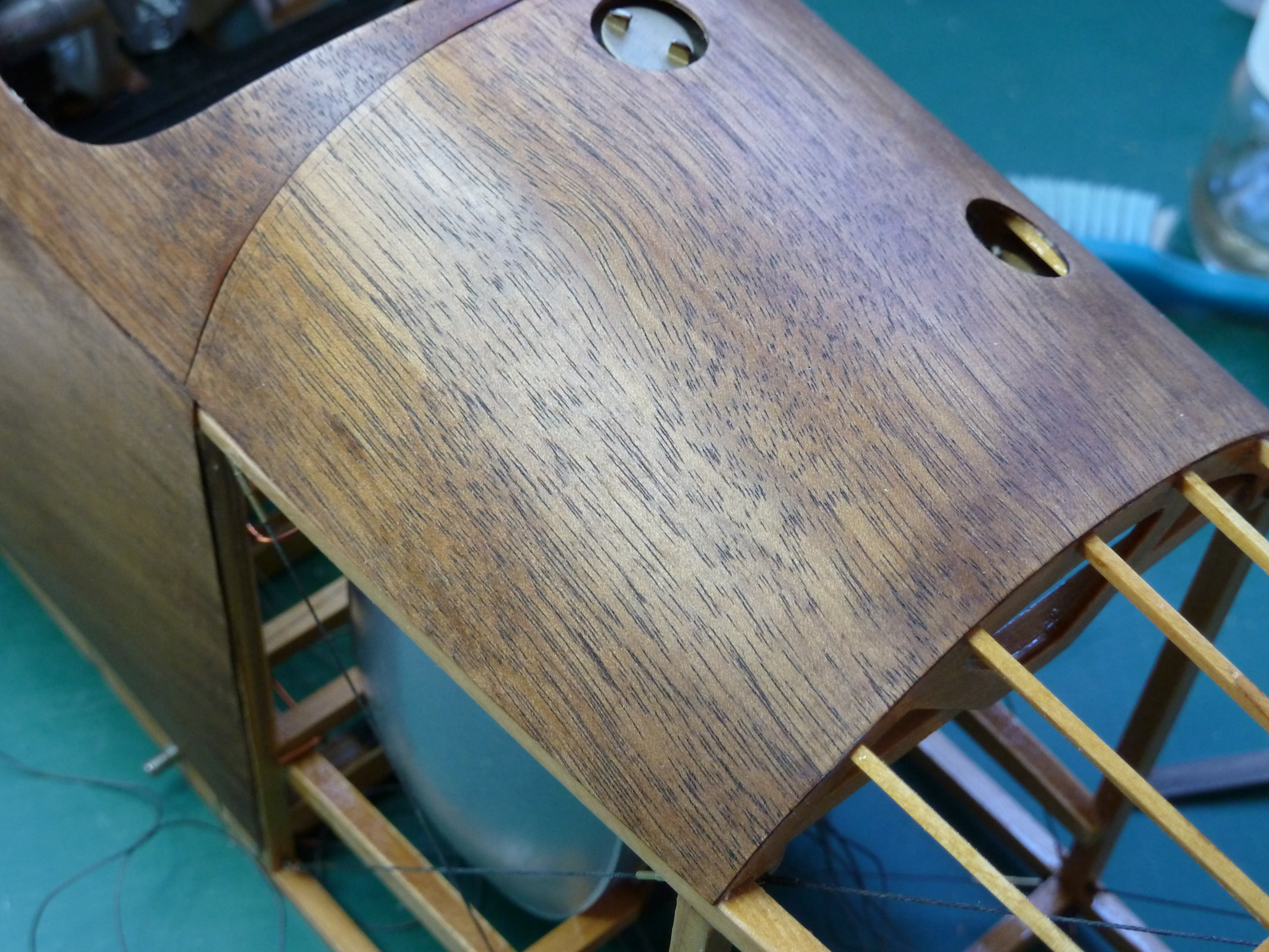
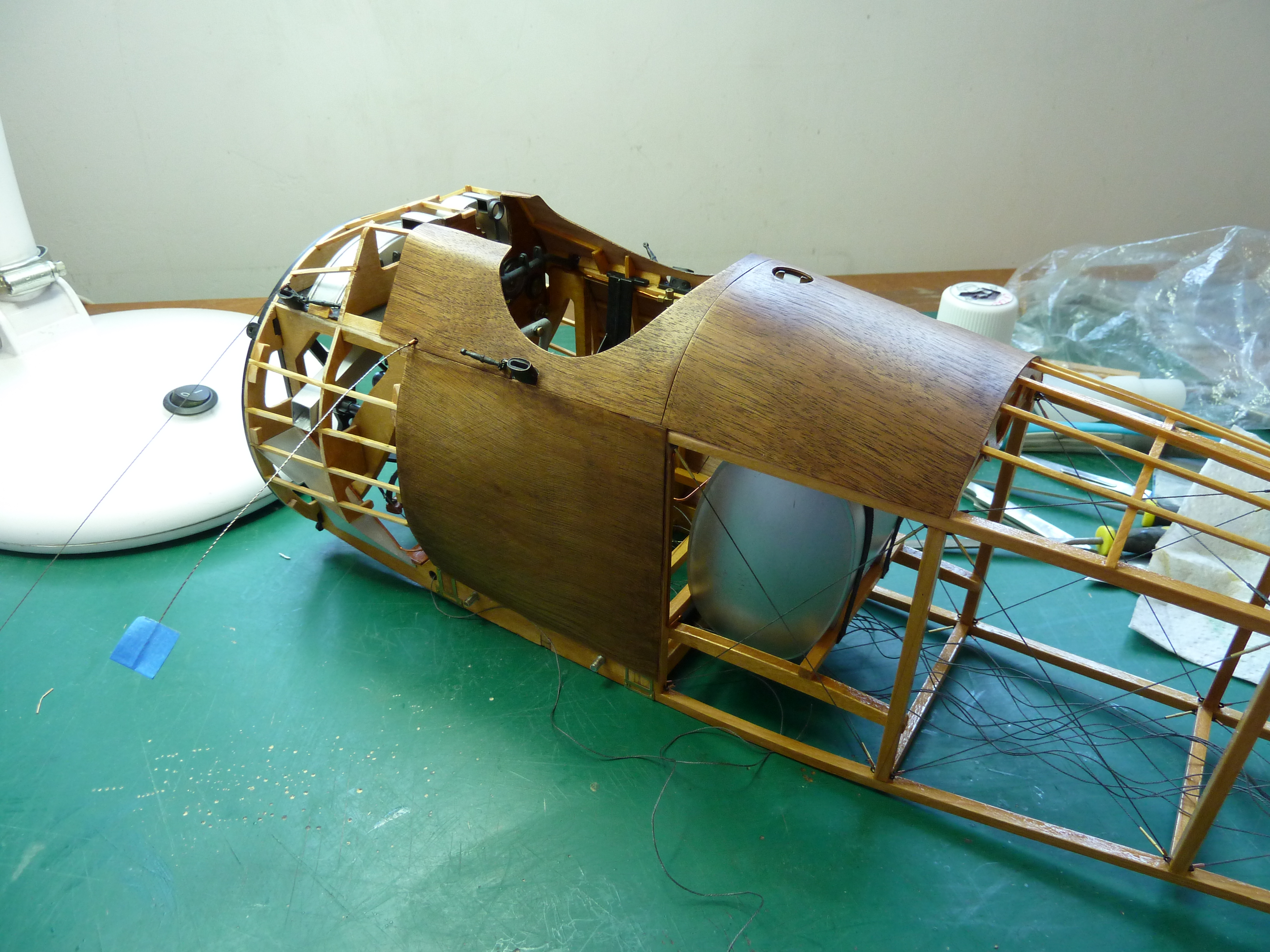
Having put the tanks in and equipped the front fuselage I then put the plywood coaming on. This wasn’t too hard. They are accurately cut by Hasegawa and provided you mock things up, take care and are fastidious about, fit they go on well. Be careful with any sanding. The top layer of the plywood is very thin and you’ll quickly be down to the second layer, which is a different colour.

As I was painting/varnishing my model I stained the panels with the same Antique Pine stain from Liberon’s that I used on the instrument panel, mainly because it was what I had, and the panel colours varied on the aircraft anyway. Having put yacht varnish on top, I think they have come out a little on the light side, but I’m reasonably happy with them. They form a really nice visual part of the model.
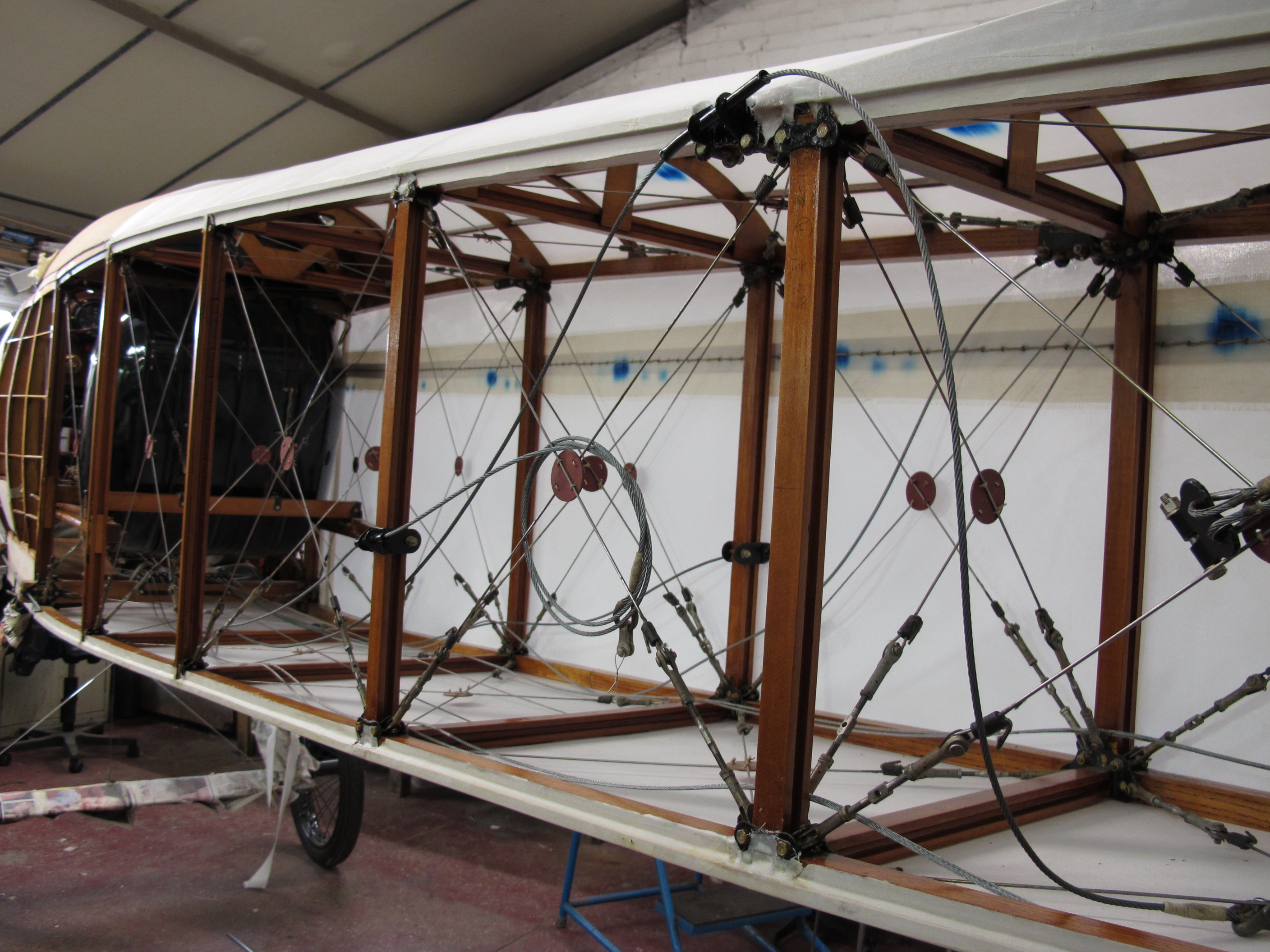
Eagle eyed viewers will also note that I’d done the rigging of the fuselage by this point too. This was done in the same manner as mentioned earlier during the assembly of the wings. One point to note is that the model includes all the external surface rigging, but omits the internal crosswise bracing for some reason. It’s not hard to add and I had sufficient spare brass lugs provided with the kit to accommodate it. The photograph below clearly shows what I mean.
The final bit of fun at the front end of the fuselage was the installation of the Lewis machine guns. They are a VERY tight fit and I had to be fairly brutal to wriggle them into position. I also had to locally file back the aluminium panels around then to allow the to sit in the correct manner. Not the easiest part of the the build so far.


Apart from adding carburettor intakes and the remaining Al panels that was pretty much it for the forward fueslage.
Next the completion of the fueslage which involved a mini disaster as a result of trying to be too clever.

I just told my wife how much I am impressed by your work.
LikeLiked by 1 person
Your attention to detail is incredible. I’ve probable said this before but it is a stunning model!
LikeLiked by 1 person
I used to be a fast jet cockpit designer a long time ago and still feel an affinity for them. It’s usually my favourite part of a build with the engine next.
LikeLiked by 1 person
As a job? That’s awesome!
LikeLike
I mainly looked after the cockpit equipment on the BAe Hawk TMk.1, 60, 100 and 200 Series, but was also responsible for the RAF Phantoms and Buccaneers.
LikeLike
That is beautiful work.Really impressive detail.The little brass fittings on the fuel gauge are very cool,where did you get them?
LikeLike
They are made from 3 & 4mm brass pipe and 1.5mm brass rod. All operations were done by hand.
The pipe sections were cut with a razor saw and mitre block and then soldered together. The rod, which makes the small handle, was cut over length, drilled to accept a vertical spindle, then held in a pin vice and hand filed to shape with needle files, which is easier than it sounds. Spin the pin vice and you naturally file the rod round. Once the basic shape was filed it was reversed and the end rounded off.
All the brass parts were smoothed off with emery paper finishing with 3000 grit. Then it was polished with Autosol and sealed with Autoglym resin polish.
The handles aren’t that hard to make holding them in a pin vice, but if you need a lot, it’ll take a while to do.
LikeLike
Thanks for that,very ingenious..It may be some time before I get to that kit,trying to reduce my stash a bit.I have two DR-1s if you are interested in a trade for something interesting?
LikeLike
I already have the DR.1. In fact I am in the research process prior to it being my next build. I don’t actually think it’s as good a kit as the Camel. There are some large and surprising inaccuracies in the kit.
LikeLike
That’s great,looking forward to the build pics!My next project is the 1/16 scale Zero,all metal.
LikeLiked by 1 person
Fabulous work! I’m fortunate to also own this kit – along with the other three in the series. I’ve been putting off starting this model, but having followed your progress, I’ve been inspired to make a start. I’ve been collecting research material over the years – the latest addition to which is the new Haynes book on the Sopwith Camel, which I would highly recommend. Here’s a link to a sample PDF: https://haynes.co.uk/sites/default/files/see_inside_pdf/H5795-spreads.pdf. This can be purchased in print or digital format. I bought the print version via Amazon. Thanks for your inspiring work.
LikeLiked by 1 person
I’m glad I’ve inspired you. This has been the most enjoyable kit I’ve made so far.
One thing I would be interested to know about though is the wood vs metal wing trailing edges and rudder/elevators. Only one picture I’ve found shows a wooden trailing edge and it’s not 100% clear that it’s a Camel wing at that. I suspect some may have been made like the Hasegawa kit but haven’t been able to get any definitive information. If you someone could clarify the situation I’d be grateful.
LikeLiked by 1 person
Hi,
In answer to your question, the Haynes book I mentioned in my previous post includes photographs of Camels being built to authentic specifications. One picture is a close-up of the tailplane assembly with metal tip and trailing edges, as you’ve done in your build. Another shot shows the uncovered wings of the Camel – with the method of construction echoing that of the tailplane – metal tip and metal trailing edges In part the accompanying copy reads: “We have managed to get AP121 trailing edge tubing specially made – it required special rollers.” The accompanying caption also reads, “Note that the wingtips and trailing edges are in metal.”
In addition, I also have Jim Kiger’s (Replicraft) set of Camel drawings, which, as you’ve stated in a previous post, are based on original Sopwith Camel drawings. On one sheet, it shows the upper wing with an arrow pointing to the trailing edge of the wing – adjacent to which is a note stating “Steel edging A&P No121 section”. This is consistent with the quote in the Haynes Camel book mentioned above.
Finally, I have an old copy of W.W.1 Aero, in which the Hasegawa Sopwith Camel is reviewed. One area of criticism of the kit refers to the errors in the wings and tailplane. In part the reviewer states, “I find it hard to understand why 1/16th tubing was not used for the trailing edges of the wings and tail.”
Hope that helps.
LikeLiked by 1 person
Every picture I’ve seen has metal tips and trailing edges.the elevator and rudder also appear to be metal.
LikeLiked by 1 person
Thanks both of you. Whilst building the model I always had the nagging suspicion that I was making a huge basic error going for the metal.
What concerns me is Hasegawa have recently released a 1:16 Camel and it’s the same configuration as this kit. No one has mentioned it in the reviews and I find it hard to believe Hasegawa have made such a basic error.
LikeLike
Perhaps the 1/16th version is based on their previous 1/8th release – hence the consistent mistakes. I can imagine them wanting to keep their costs, particularly R&D, to a minimum.
LikeLike
One other thought… if, as that WWI aero comment stated, 1/16th tubing could have been used on the trailing edges of the wings and tail of the 1/8th model, then in theory, to be in scale, the trailing edges of the 1/16th model would have to be 1/32nd, which from a production point of view, particularly in an all-plastic production, would probably not have been viable.
LikeLike
Interesting that it says 1/16 or 1.5mm. I tried that and it looked oversize, so I went with 1mm in the end which is a bit too delicate really. If the model knocks against anything the annealed brass bends readily. It maybe because I was using round section wire though rather than the proper section which is flattened. 1.5mm would have made a much stronger model. Steel is just too hard to work with though, which was the other option.
LikeLike
The 1:16 kit is a straight copy though. They haven’t tried to replicate the tubing at all.
LikeLike
That’s interesting… I’ll bear that in mind when I come to build that section. Thanks for the tip!
LikeLike