
The last few days have been spent adding extra detail in the cockpit area and modifying the kit’s layout.
The cockpit layout information that I’ve found has been less than comprehensive and with quite a few variations, but none of it has looked much like the layout provided by Hasegawa. In particular the row of instruments mounted between the guns seems especially suspect.
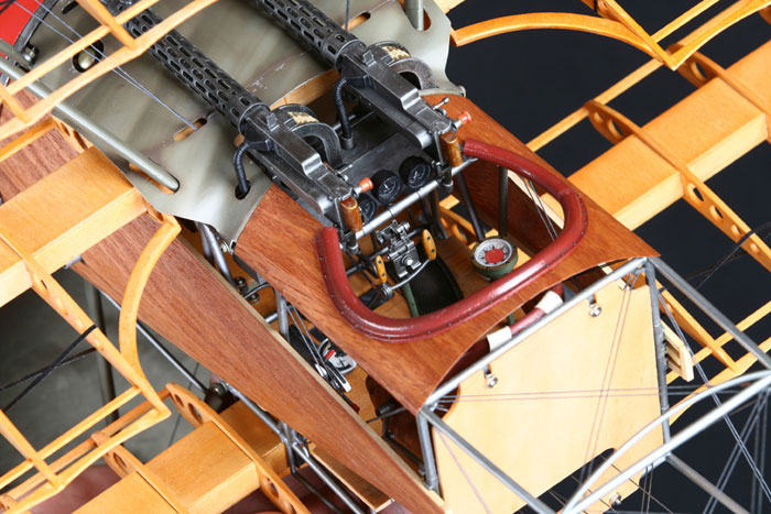
You can just see them in the photo above of Patrick Chung’s model which was built as designed.
However, a photo of Richthofen’s final aircraft shows a crash pad across the back of the guns which would’ve obscured any instruments there.

None of the authentic Dr.1 replicas I’ve seen have instruments there either, so I’ve decided to abandon them and attempt to replicate the most common layout I’ve seen in the various texts.
The first change was to introduce an altimeter on the starboard side of the cockpit. This was suspended on three springs, I assume to protect the delicate barometric mechanism from engine and gun induced vibrations.
The finished item is shown installed below.

To make the altimeter I cannibalised the kit’s rev counter. First I removed the fixing lugs and installed small loops made from 0.5mm stainless steel wire (the making of which is detailed further down this post). I was intending to use the same wire to make the suspending springs, but then I had a bright idea…
I had already obtained some guitar strings to use to replicate the interrupter connections to the machine guns. The strings comprise a central 0.5 mm core wire with another wrapped around in a spiral, and looking very spring like. By unwrapping some of the outer spiral to expose the core I was able to simulate a spring much more neatly than I could’ve made myself. I then formed a loop at each end of the core to suspend the altimeter from.


I’m quite pleased with the result.
One area where I did compromise was on the dial face. I’ve actually used the RPM sticker supplied in the kit. I did consider making a proper altimeter decal, but that would have required a lot of messing about with AutoCAD and Photoshop and I didn’t think it was worth it, particularly as the model will end up being suspended from the ceiling.
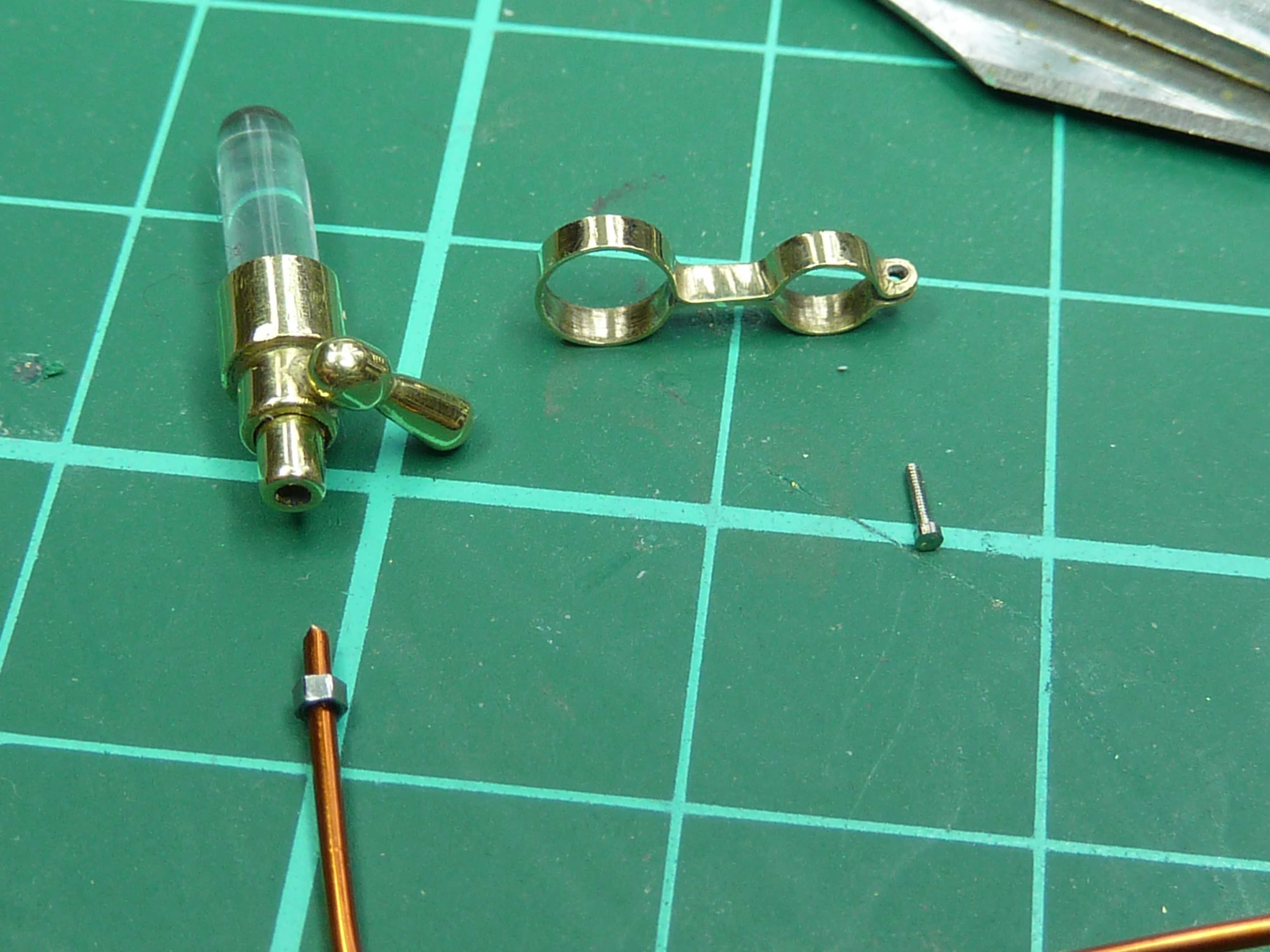
Another item I have included is the pulseometer. This was supposed to enable the pilot to monitor the flow of castor oil to the engine by pulsing up and down as each squirt of was fed into the crankcase, though contemporary reports indicate that it was less than effective.
The kit completely ignores this item so I had to make one from scratch using brass tube, rod and a piece of clear plastic sprue polished up.
The main parts are shown below:
And here it is installed in the kit:

The ‘glass’ section looks a bit too tall now it’s installed, but it’d be a major job to change it, so it’s staying as it is.
Another minor bit of detailing concerned the compass deviation card. This was fitted to the rear of the ammunition bin above the pilot’s left leg. Rather than make a decal for this, I simply knocked one up in Excel and printed it to scale on photo paper. I then stripped the backing off the paper to get it down to a realistic thickness and fixed it in place with CA glue.
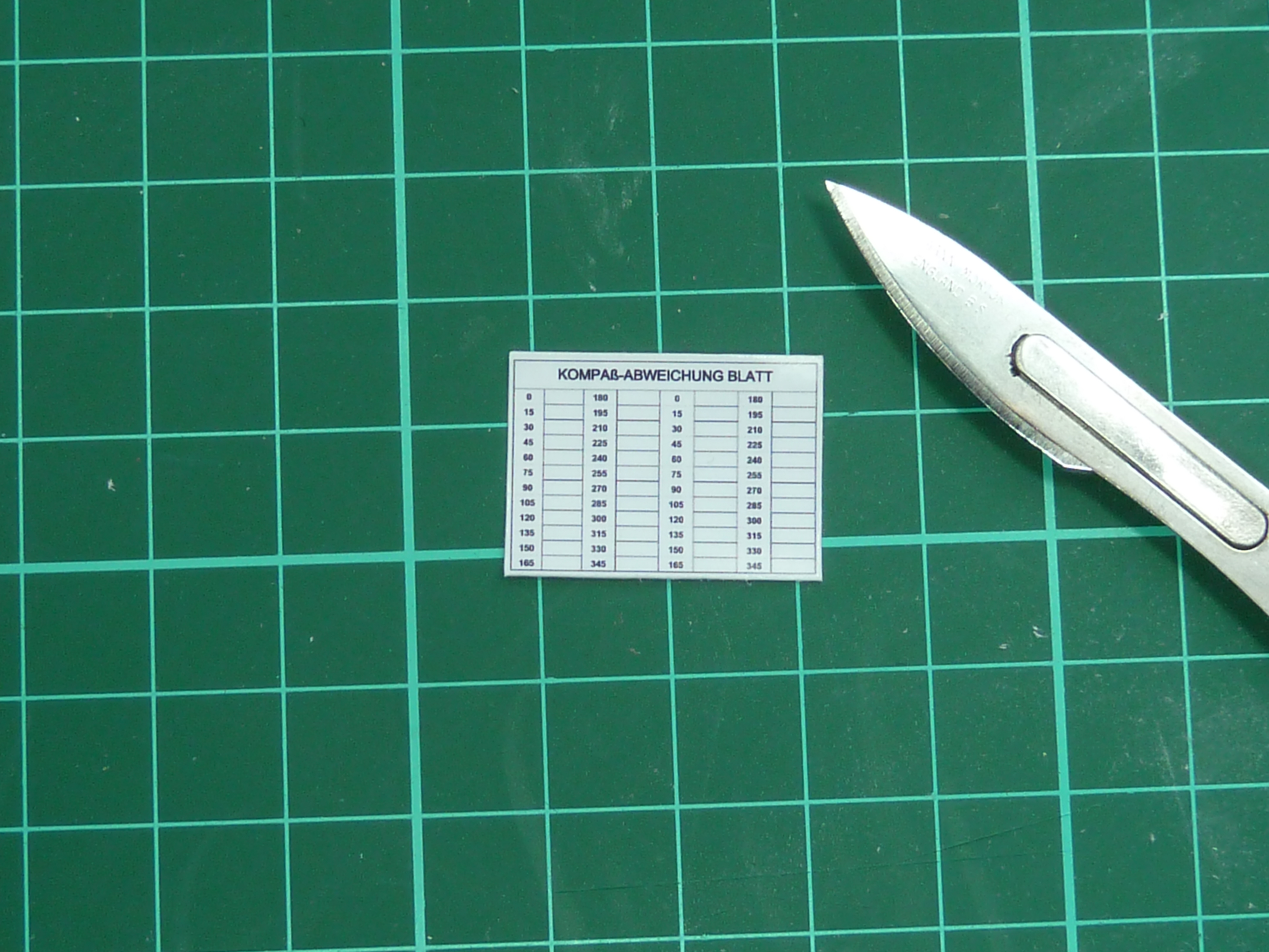
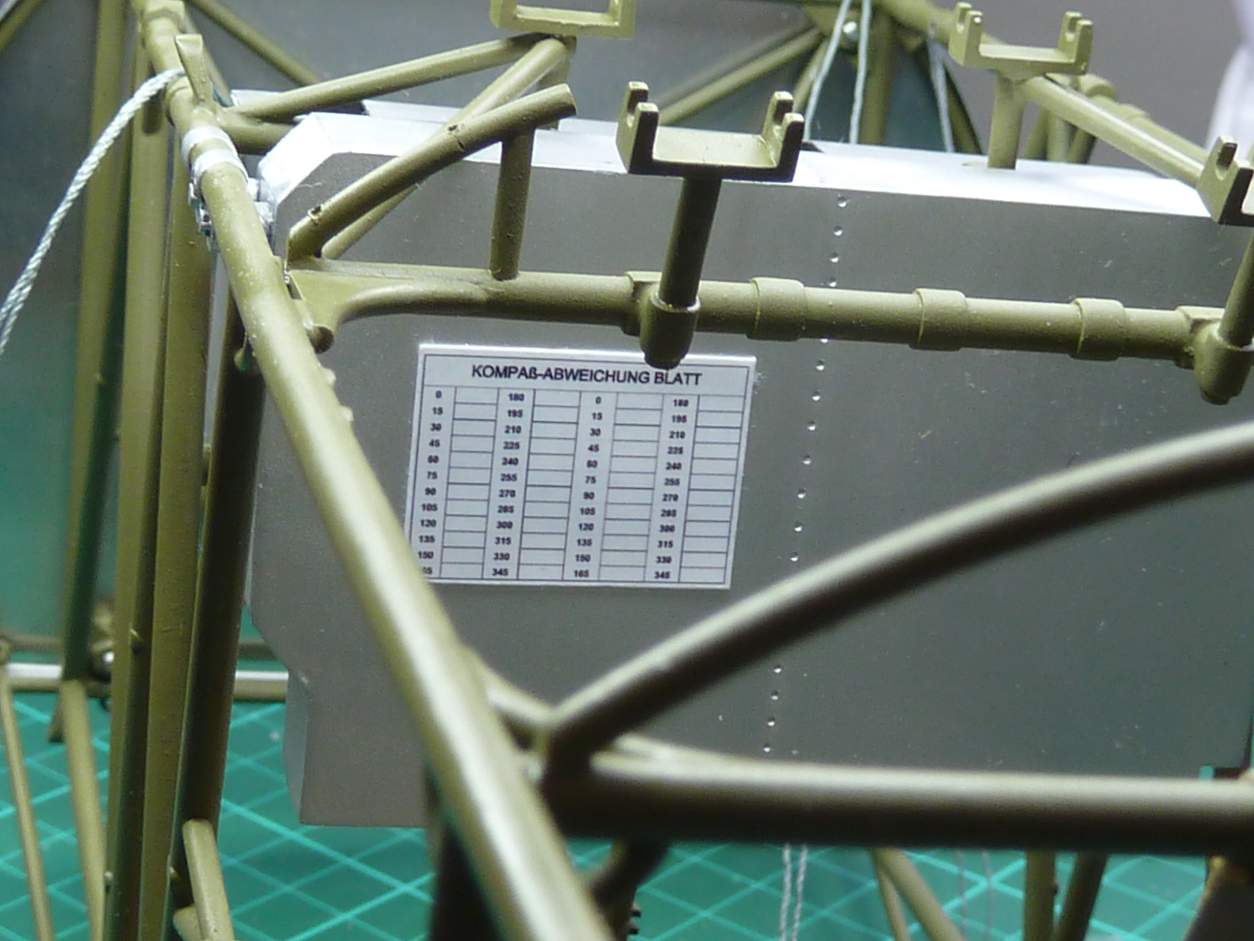
Obviously the compass swing has yet to be carried out on this aircraft as there are no actual deviation figures entered on the card (?!)
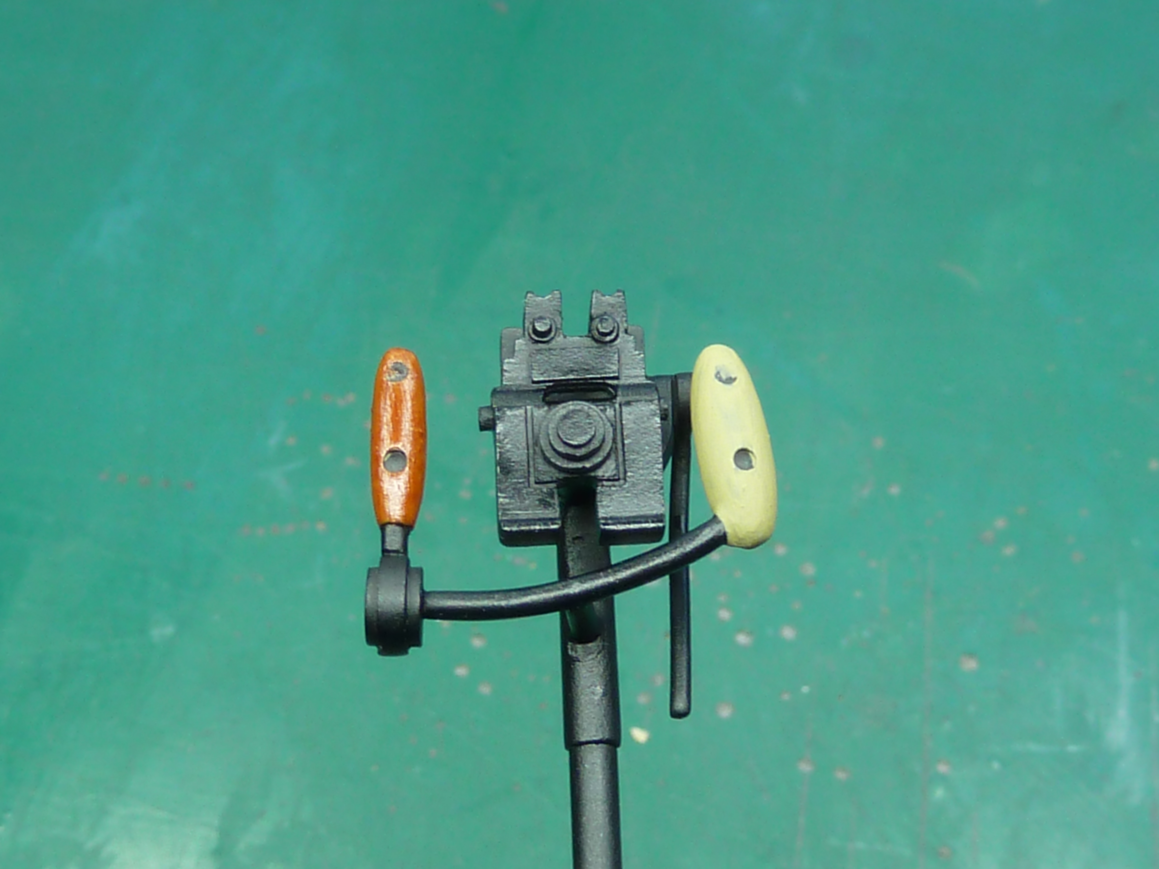
At this point I also installed the control column and rudder pedals. There’s not a huge amount to say about them, other than I fitted them too early.
The only detailing done was painting the column grips with artist’s oils to simulate the wood. The one on the right below is in the base colour. The one on the left has had the oils applied. The screws were eventually painted silver once the oils were dry.
I should have included some bowden cable links from the gun triggers to the guns, but I didn’t realise they existed until after I’d installed the column in the cockpit and it would be very awkward and risky to try it now. I may also add some “L” and “R” decals to the gun triggers, but I think I need to get dry transfers to do it as the letters need to be red or white from what I can tell. It’s something I can add later though.
Next was to include some turnbuckle adjusters in the control lines. I should’ve done this before I installed the control column and rudder pedals in the aircraft, but in my excitement to see some progress I forgot.
Previously during the Camel build I made some faux turnbuckles out of brass tube threaded onto the lines. These were better than the kit’s offering, but not really accurate. So this time I’ve decided to see if I can improve things a little further by adding the mounting loops at either end.
These are a bit of a pain to make and get even. I spent some time fiddling about trying to develop a method for making them. Eventually I used a pin vice and 1 mm drill to form them. The drill was put in the vice backwards, then the tail of the wire slipped into the gap between the pin vice collet’s jaws to hold it while the wire was wrapped around the drill shaft in a single spiral.
Once removed from the pin vice, the tail was trimmed off and the spiral pressed flat to form the loop in a ‘p’ shape. I then held this in some pliers and used the pin vice drill to pull the loop across until it was centered.
It’s difficult to put into words but hopefully the following pictures make it a bit clearer.


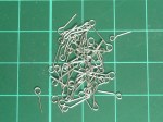
By my estimation I’ll need over a hundred of these things to complete the model and so far I’ve made about 60 but run out of wire, so more is on order.
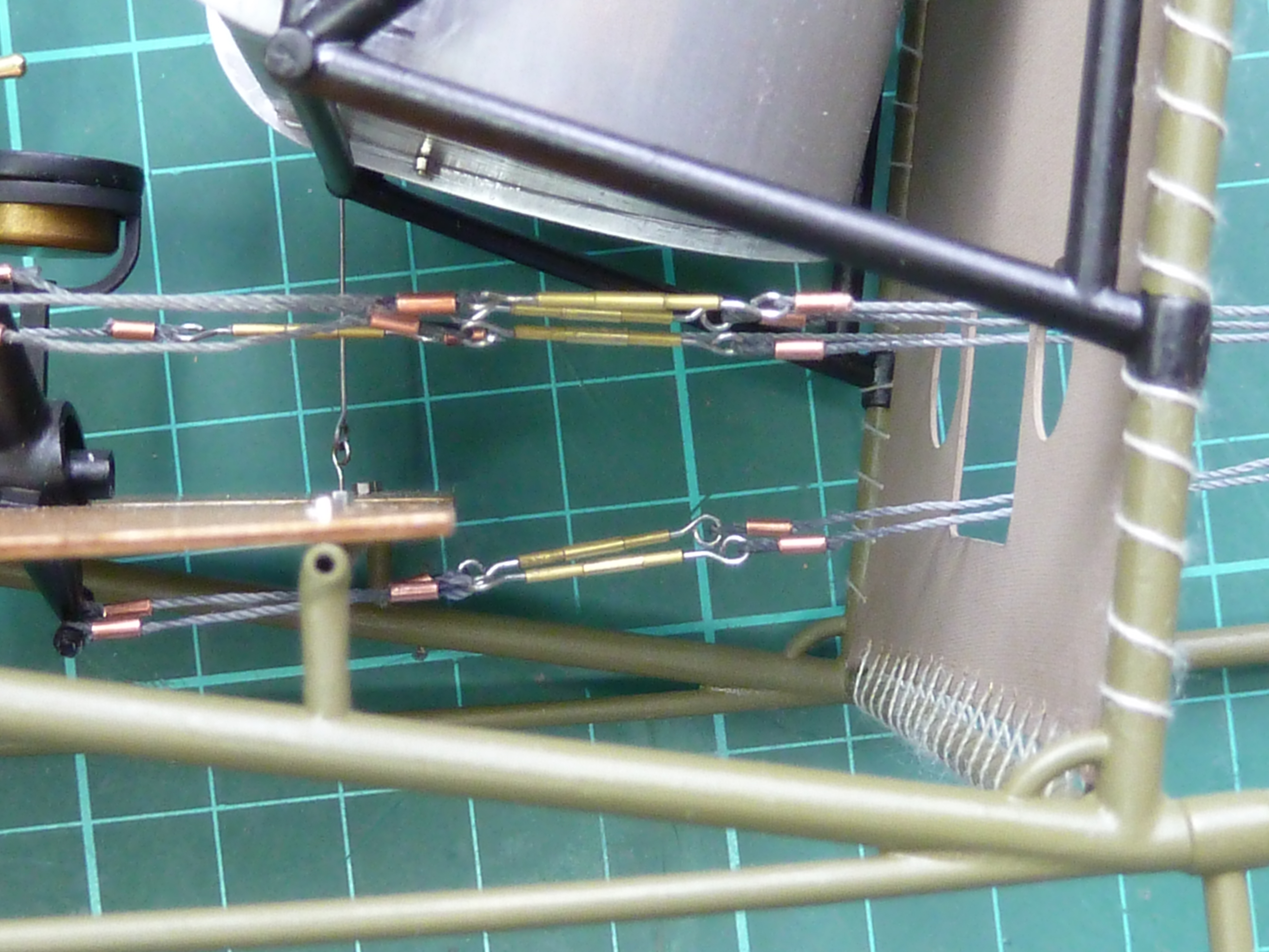
To make the actual turnbuckles the mounting loops are glued into the 0.8 mm OD brass tube with CA glue. The revised turnbuckles are still not completely there, but they’re better than the Camels.

And here they are installed in the control line runs under the pilot’s seat.
There are still a number of other bits of detailing ongoing, but this post is long enough I think, so I’ll address those in the next one. Oh, and then there’s ongoing disaster known as the tailplane…

I truly enjoy your workmanship and ingeniosity.
LikeLiked by 1 person
Not only is your craftsmanship exquisite but I love learning about the airplane from these posts. Thank you!
LikeLiked by 1 person
The lengths you go to for authenticity are incredible. I’m in awe!
LikeLiked by 1 person