
It’s been a while since my last post, but I’ve been busy in the interim completing a lot of detail tasks on the Fokker as well as building a second 1:72 Hawker Hurricane and diorama, as I liked the one I made for my friend so much I wanted something similar for myself. There are still a couple of figures to complete for that, but I’ll put up a short post on it when they’re done.
So a fair amount of activity without a great deal to show for it.
First up: the completion of the fuselage rigging.
I’ve wasn’t happy with the Hasegawa method of simulating rigging turnbuckles on the Camel and so developed a slightly better version of my own. However, that didn’t really capture the full effect, so I hoped to improve on it with the Fokker. A pic of the Camel effort is shown below.

My initial idea was to make the turnbuckles out of brass tube and stainless steel wire, as detailed earlier in this blog. However, I thought I’d try a plan B and attempt to make moulds from some suitable turnbuckles that I have left over from the Camel model, (Hasegawa provide injection moulded ones for the external rigging) then cast the them in white metal.

I’ve never done white metal casting before and suspected that I wasn’t starting with the easiest subject. However, I made a mould in RTV rubber and had a go.

The bottom part of the mould is shown being made above. Once cured, it was sprayed with release agent and the second half poured on top. Making the moulds was actually very successful and much easier than I expected.
Problems were however encountered in the actual casting. some of the runs in the mould were very thin and as I suspected, I had problems with getting the metal to flow through them without it prematurely solidifying, resulting in unfinished components. I could have experimented with heating the mould before casting and improving the pressure that metal entered the mould at (by increasing the head of the pouring reservoir), but it was all getting a bit too complex and I thought I’d leave perfecting my casting skills for another day and easier project.
So back to Plan A.


Over 50 of these were required so a sizeable amount of effort went into making them all. Once complete, the actual rigging didn’t take that long. One thing I did find was that the rigging had to be as slack as you could get away with, as any real tension in it started to distort the plastic fuselage all over the place. Also, in retrospect, I wish I’d used aluminium tube for securing the thread to the eyelet. The copper looks odd.
The actual rigging on the Fokker looks as if it is doubled up, but in reality each wire is a loop. The completion of the rigging has however made the fuselage look much more complete.


In addition to completing the rigging I also got around to finally attaching the rear decking which I made ages ago. I’d left it off to allow access for fitting the rigging.
Despite storing the decking in a curved state it was still difficult to get it to sit properly on the top of the fuselage.. in the end I had to resort to pinning it in place with some 0.5mm brass wire which was then sanded flush to the surface.


I also finally fitted the plywood on the starboard side of the front fuselage as I no longer needed access to the cockpit. The side pieces are straightforward to fit, the only change I made was to extend the central baton back to the next frame as it was on the real aircraft.

Apart from repainting of the fuel tanks and filler caps where they have become scratched during test fittings of wings and aluminium panels, there is little to do on the fuselage now except cover and paint the port side. I’m still considering how I’ll actually do that as I suspect it will be far from straightforward…
In parallel with the fuselage work I have also completed the ailerons. These suffered the same problem as the tailplane in that the ribs distorted under the heat required to shrink the Solartex covering. here’s a picture of the port aileron after the Solartex had been stripped off.

The problem did however resolve one other issue that I’d been procrastinating over.
Von Richthofen’s DR.1 was one of the later build aircraft and so had the later style ailerions whereas the Hasegawa kit comes with the early style. I’d wondered whether it was worth the effort to convert the ailerons to the right standard, but having written off the port one it seemed logical to build the replacement in the correct style and convert the starboard one too.
The difference is in how the inboard part of the trailing edge fairs into the wing. On the early ailerons it takes two bays, on the later ones, only one. You can see the difference below.

The lower edge is the early style and the upper edge the later style. It is presumed that Fokker changed it to ease production as it reduces the number of different ribs required.
As with the wing, the trailing edges were actually wire, not wood, but I stuck with wood for the covered aileron for simplicity. The bare starboard one was converted to wire using the wire supplied in the kit. Brass wire and tube were used to construct the replacement aileron.

To convert the starboard one simply required a new rib making out of plasticard, which you can see in white below.
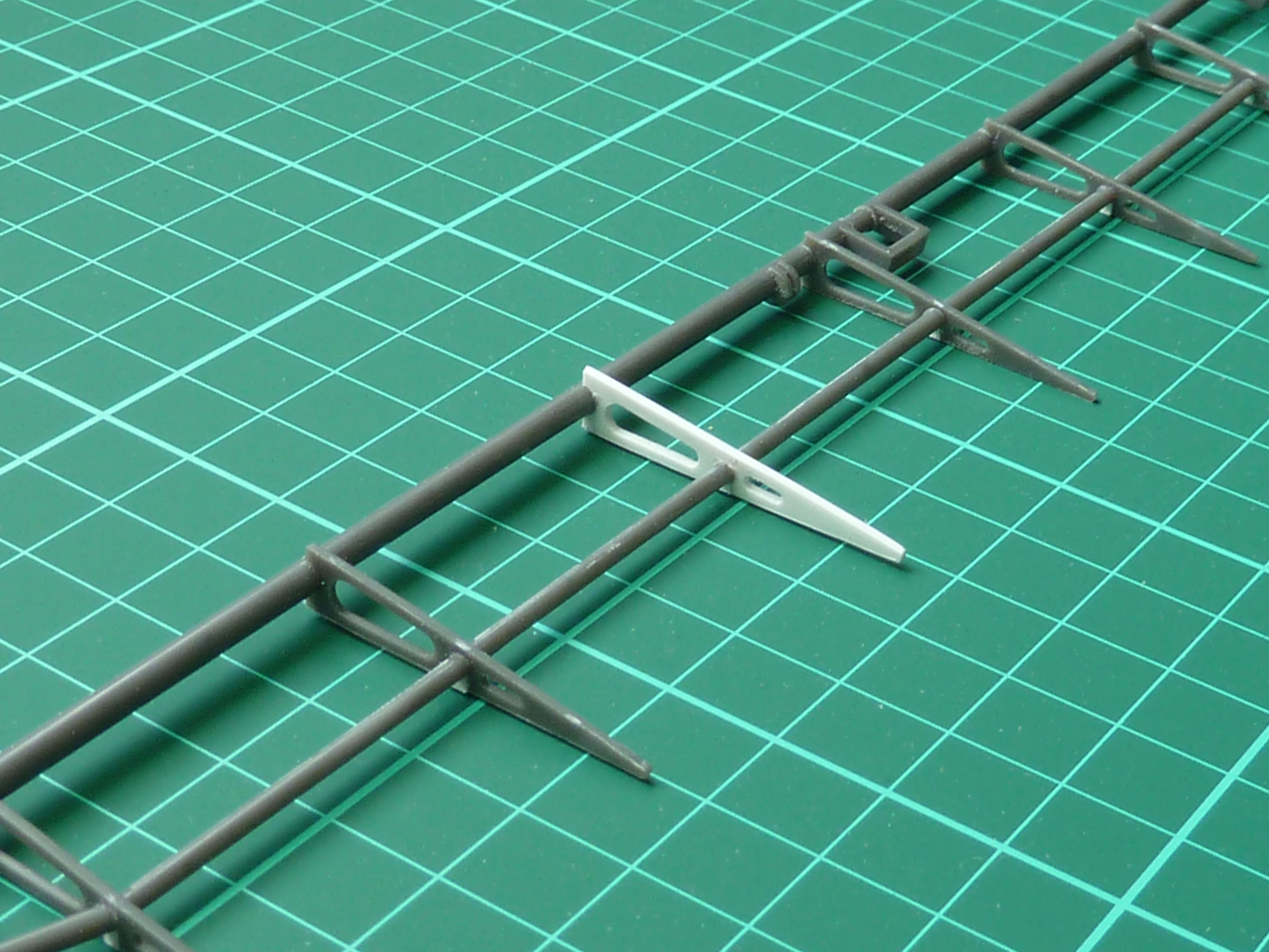

The tube going through the ribs at the mid point seems too far forward to me. The pictures I’ve seen seem to have it much closer to the trailing edge: At about 2/3 chord rather than at the mid point. I’m not certain of that though so I didn’t change it.
Then it was simply a case of covering and painting for the port aileron, and painting and adding the trailing edge wire for the starboard.


I am still amazed even if I try not to…
LikeLiked by 1 person
incredible work.WOW
tedious but those details will be worthwhile tremendously, no?
LikeLiked by 1 person
Just discoverd your build of the Hasegawa Dr1,love your attention to detail,What is your opinion of the “FineArts Models” 1/15 Dr1 made on a very limited production run of Fifty a few years back,and VERY costly.?
LikeLike
I’d never heard of it before to be honest. Having had a Google and look at it on their website it looks pretty impressive. Some curious omissions and deviations from the real thing though, especially if they were charging the Earth for it.
They’ve omitted the plywood leading edges of the wings which is one of the most significant and they’ve truncated the rear decking around the cockpit too. The axle beam is wooden on their model and it was most definitely an aluminium assembly on the real aircraft.
LikeLike
Thanks for your comments ,the “Fine Art Models” Dr1 ran about eight thousand American dollars,and is interesting to see the very omissions they failed to incorperate in such an elaborate and expensive model,as you have pointed out. I think they were made in Luxemburg if I’m not mistaken,one wonders were they obtained there data in the building of this model, still beautiful though! Also,will you in the future do a build of the Hasegawa SE5.Thanks again from NOT so sunny California.
LikeLike
I’m in two minds about the SE5a. I’d like to do it because then I’d have done them all (I have the 1/16 Wright Flyer in my stash) and it’s the aircraft of Albert Ball. However, they are very expensive now, more than I think they are worth.
I’m also getting the info together, as a long term project, to do a 1/8th scratch build Sopwith Pup. I’ll need to get the engine and cowling 3D printed which means working up CAD .stl files.
LikeLike