
This is the final installment in the build of this model as it is now complete and can be viewed in the Gallery section of this blog.
Only the pushrods and valve gear remained to be completed since the last update. The kit’s versions are quite good, and I used them pretty much unchanged on the plastic kits, bar the introduction of some home made springs and thinner steel rods. This time I wanted to go a little further.
The rocker arms on the real engine are held in some stirrup brackets mounted on posts, as you can see in the photo below on The Vintage Aviator website.

I wanted to try and replicate those as far as I could. In order to ensure I got them all looking identical I decided to try my hand at making some photoetch parts.
After a quick session on CAD I’d finished the artwork and used it to create the etch masks on both sides of some thin brass sheet. These masks are no different to the normal, except you are etching the sheet from both sides, so you need one with a mirror image of the other for the back and some alignment marks so that you can accurately line both sides up.
[For more info on etching see my earlier post Come And See My Etchings Upstairs…]

I stopped the etching process before it was entirely complete. For some reason the last bits seem to take ages, and I was worried about undercutting the masks if I left them in the acid too long. I’ve now added a small aerator pump from an aquarium to my etch bath, and the agitation caused by the bubbles is giving me much more even etching results.

Despite the small amount of flash, for want of a better word, on the pieces it was a simple job to clean them up and bend them to the right shape.
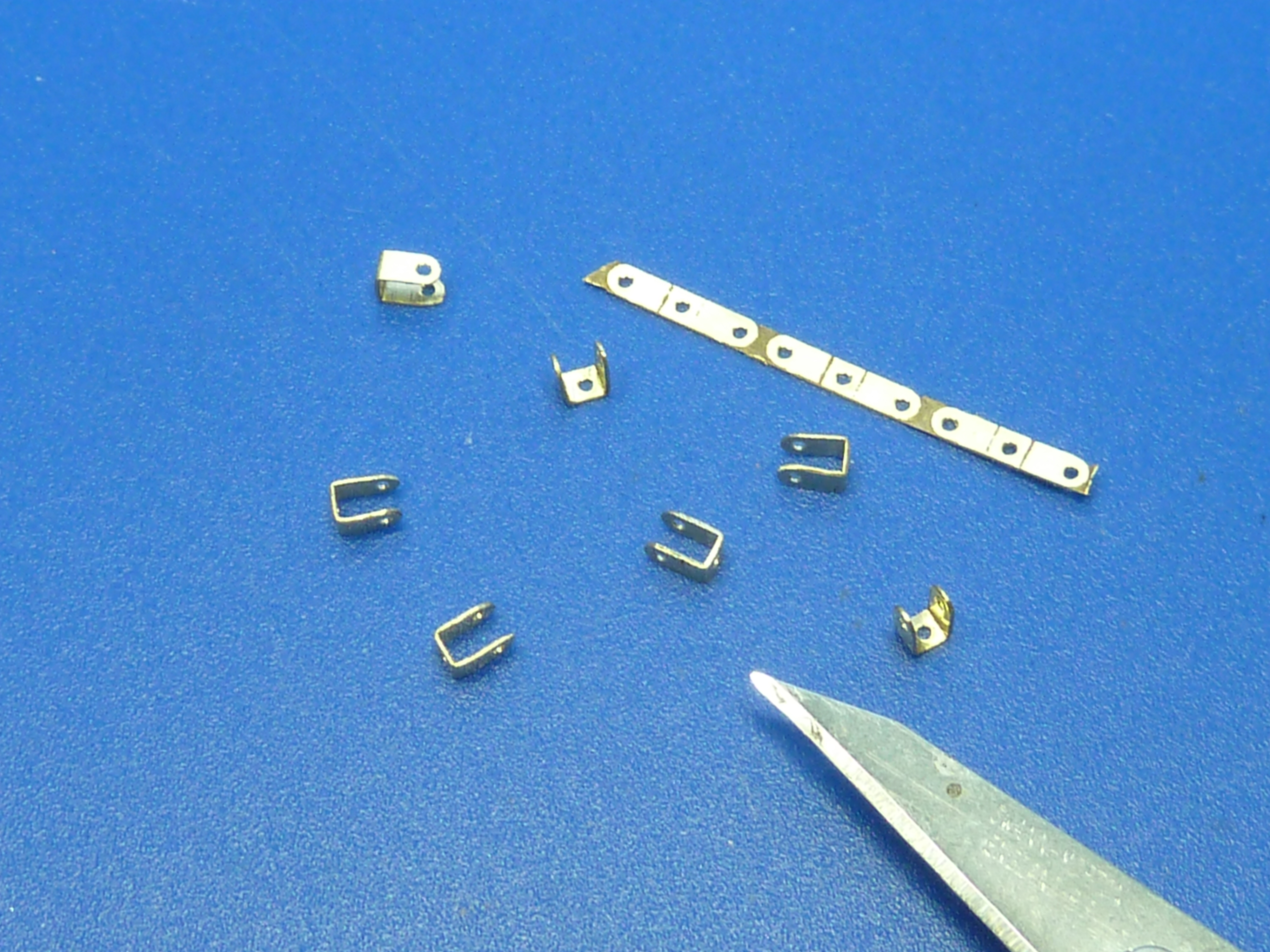
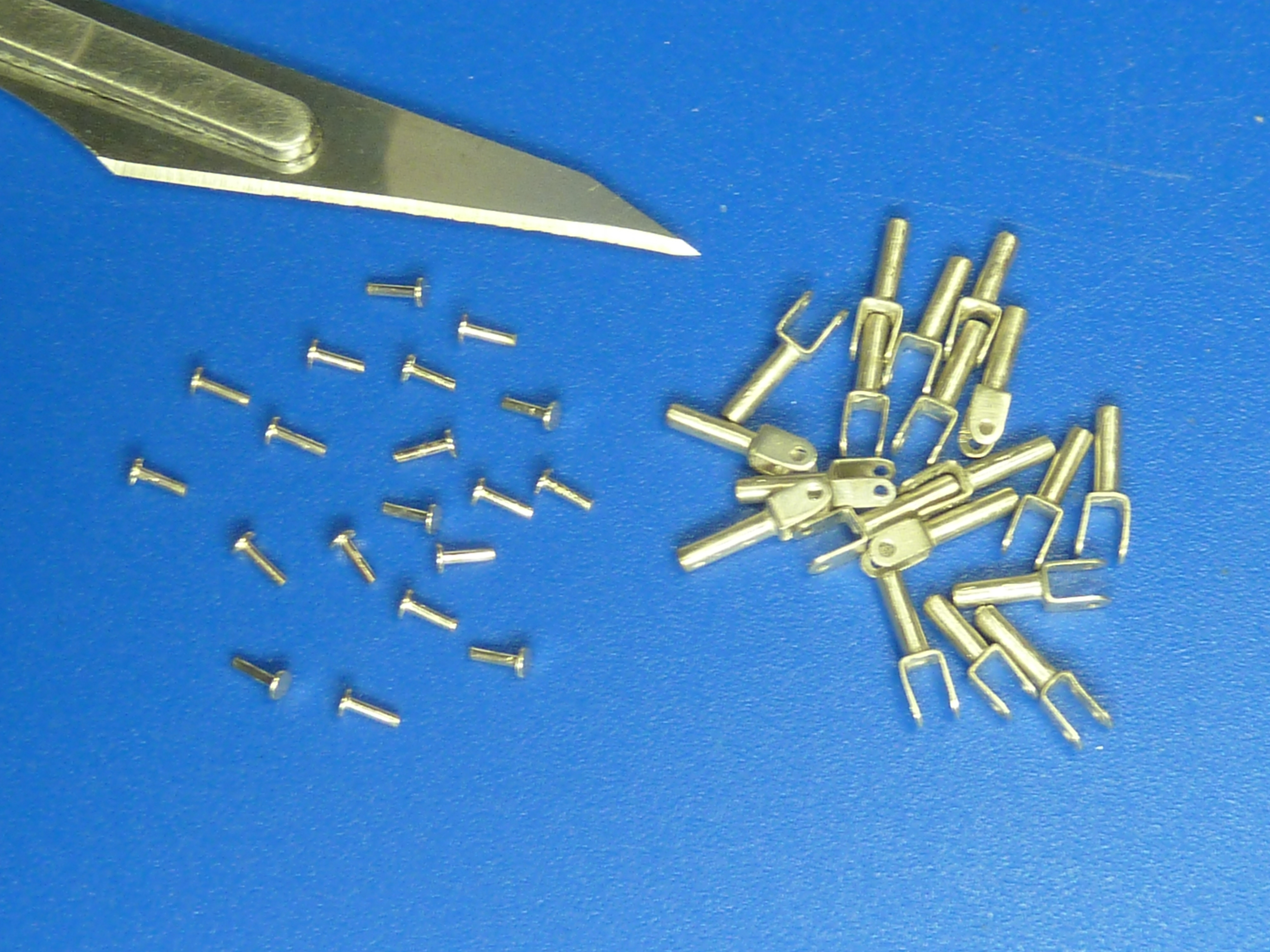
Once that was done I soldered them to some 1.5 mm brass tube. I used a small piece of brass rod to hold the stirrup central on the tube while I soldered it, hence the hole in the base of the bracket. Once soldered I filed the remaining spigot of brass wire away to leave a clean base to the stirrup. The final operation was to cut some small brass pins to length to form the rocker pivots. The whole lot was then nickel plated.
Next up were the rocker arms themselves. The ones in the kit are quite nice actually, but I found them hellishly fragile. I did have a go at modifying a couple of them, but they both broke in the process. The alloy used in the kit is just too soft, or I’m too rough.
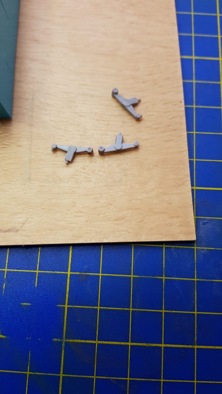
So I decided to make my own…
The kit version is shown behind the prototype of mine. I was reluctant to abandon them to be honest, as they do look sharper.
I utilized some of plastic ones as masters to make a RTV mould. They come from a part completed plastic version of this kit which I am building in the background for quiet relief.
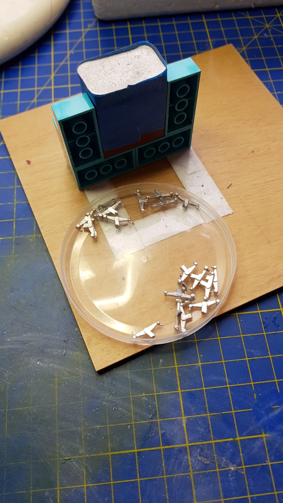
They were used to make a simple mould which allowed me to cast as many as I needed in a high tin content alloy. The result was a set of rocker arms that would withstand the fettling required to fit them.

Halfway through the casting process. High tech stuff as you can see. I only need to spend a few more thousand pounds and I’ll be able to get the same sharpness as Hasegawa. Apologies for the quality of the these shots they were taken with my phone, and I forgot to go back and take some decently lit ones with my camera.
I found out recently that there are a number of jewelry casting firms who will take a CAD model and turn it into a finished casting for you, which would improve the quality considerably. I suspect it wouldn’t be cheap if you were making 18 items though, but you could mount them on a sprue and call it one piece…
The finished and fettled castings.

After copper plating.

After a quick ‘ageing’ in burnishing fluid.

I’ve seen the rockers copper plated on a number of museum engines. I’m not sure why they did it. It would protect against corrosion, but there are numerous other parts of the engine which have been left in bare steel, so I can’t believe it’s because of that. Neither can I believe it was just for aesthetics. Odd…

After completing the rockers I moved on to the “Grasshopper” valve springs on the exhaust valves. No, really. That’s what they are called in the Gwynnes Ltd. parts manual. The wartime codename for them was “Hinip” for what it’s worth (all the parts have codenames associated with them).
The plastic kit has some notional springs moulded in, but they bear little relation to the real thing. When I previously made the plastic kits I replaced them, but wimped out of making proper grasshoppers, and went with the traditional coil spring which was an alternative part according to the manual. I believe the grasshopper springs were developed to overcome heat problems.
The kit does come with some very nicely made steel ones, which I thought I could use. However, when I got them out of their packet they also bore little resemblance to the real items. They also appeared to have some form of black passivation treatment on them, which would’ve made them very hard to plate (the real ones were a shiny silver).

The real thing from a photo on The Vintage Aviator website.
This time I decided to go for it and see if I could make them. After a bit of cogitation I developed a jig to form my own. Initially I followed the mounting strategy of the kit’s version, but after a couple of iterations decided the way the real springs were mounted was actually better and easier, so I went that way.

The kit’s springs locate vertically in a hole in the cylinder head. If you look closely at the picture from the Gwynnes parts manual above you can see that the springs locate horizontally through holes in the cooling fins.
The revised jig designed for horizontal locating points.

The final design of the spring.
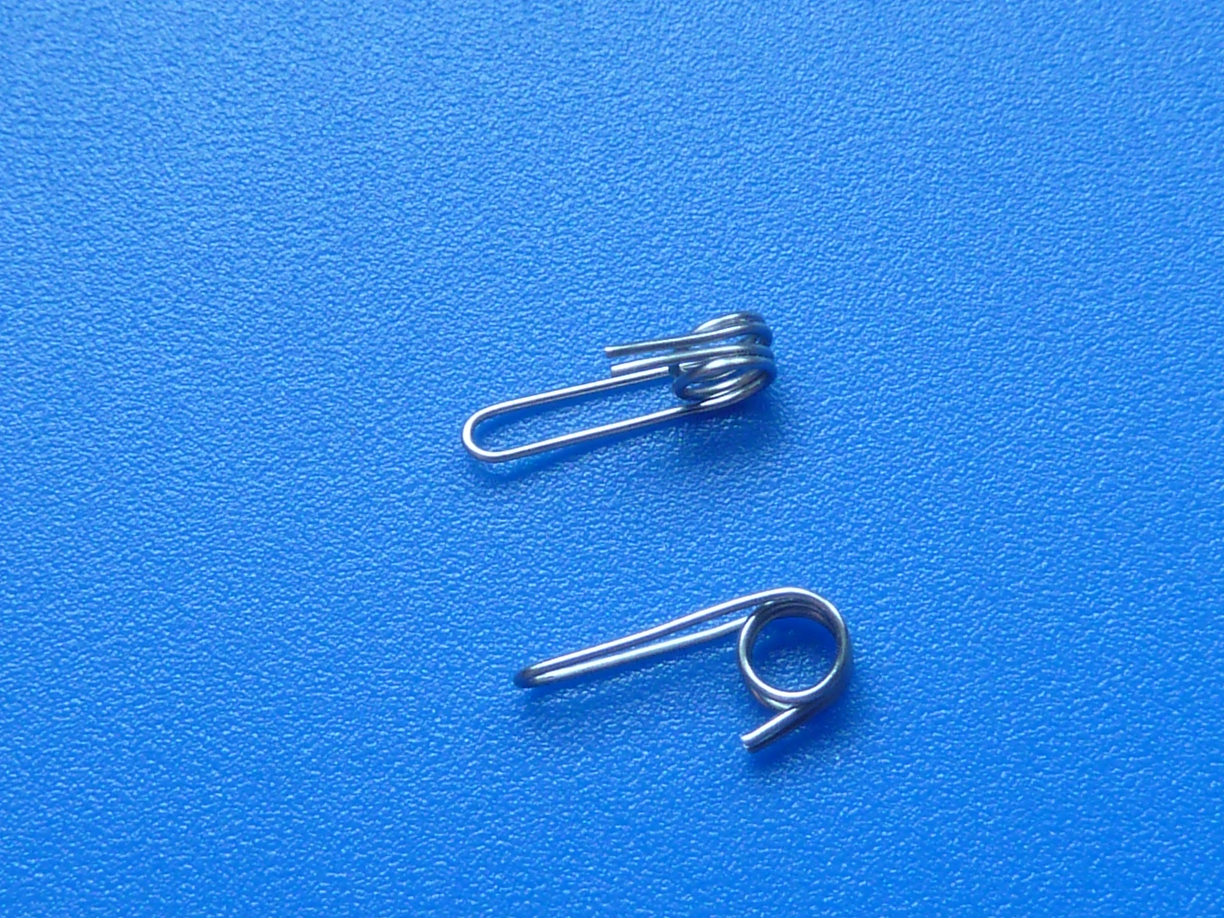
I used 0.5mm SS317L stainless steel wire. The L means it is low carbon, so it is very ductile.
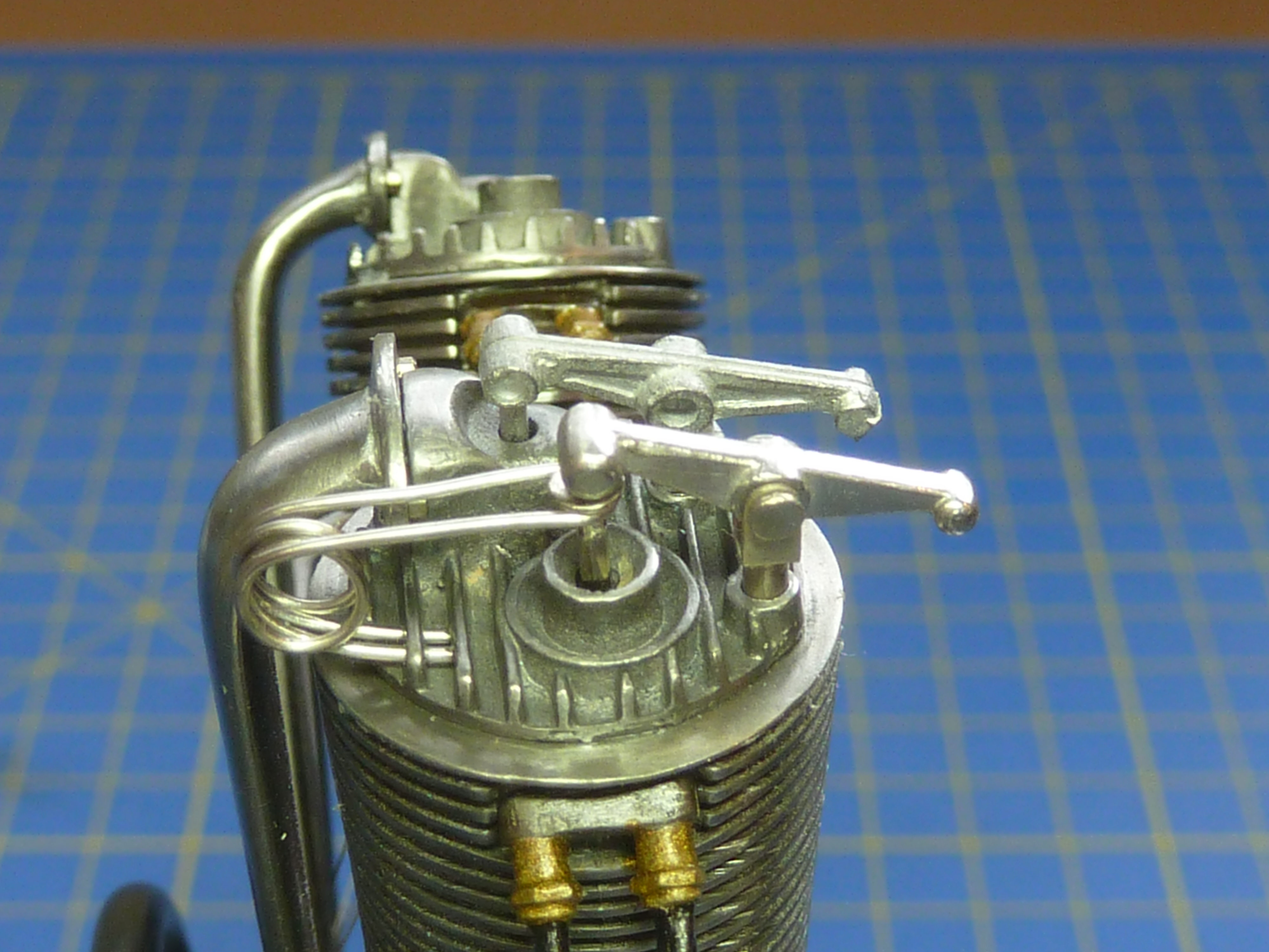
The final result is shown below.
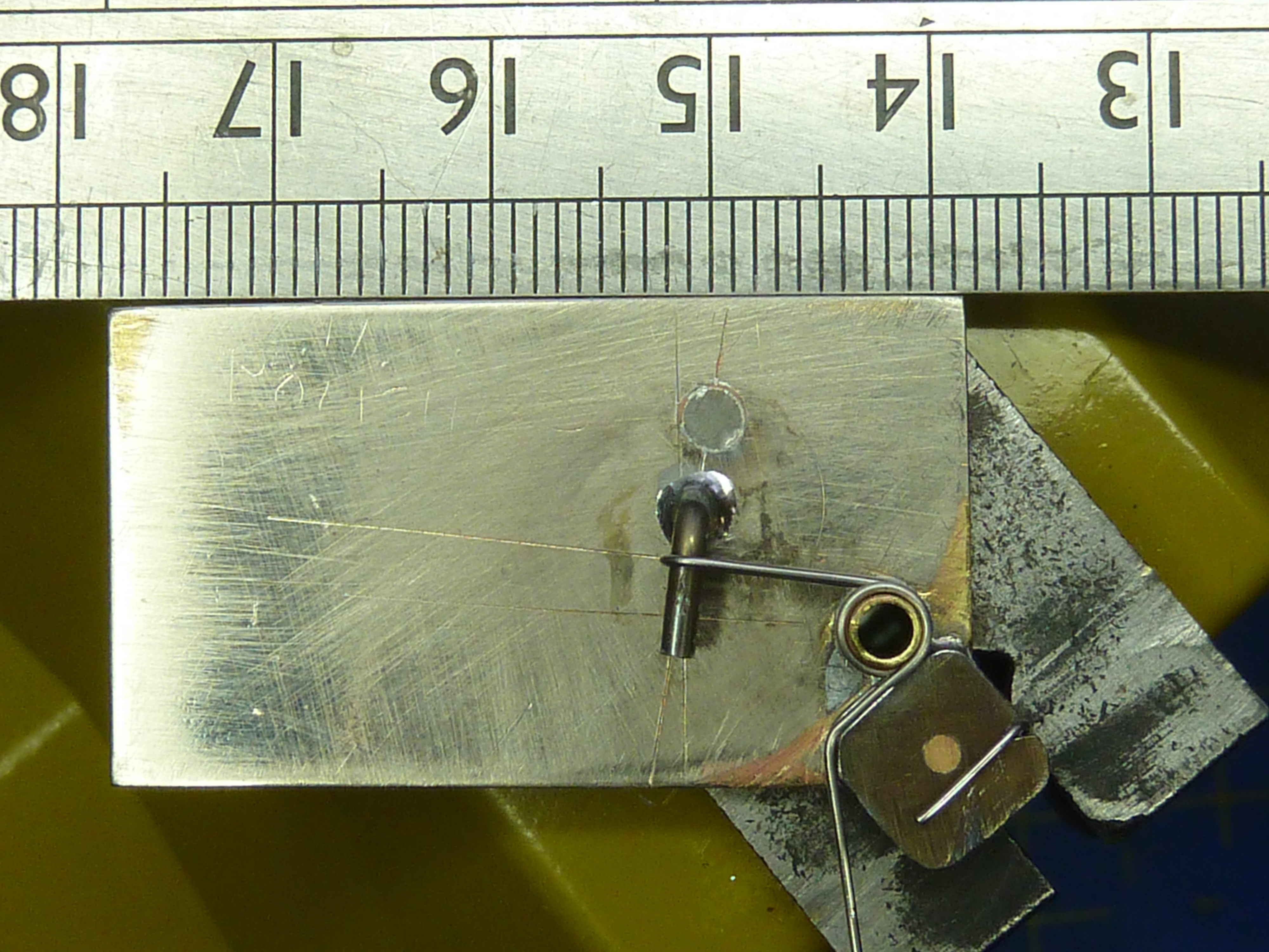
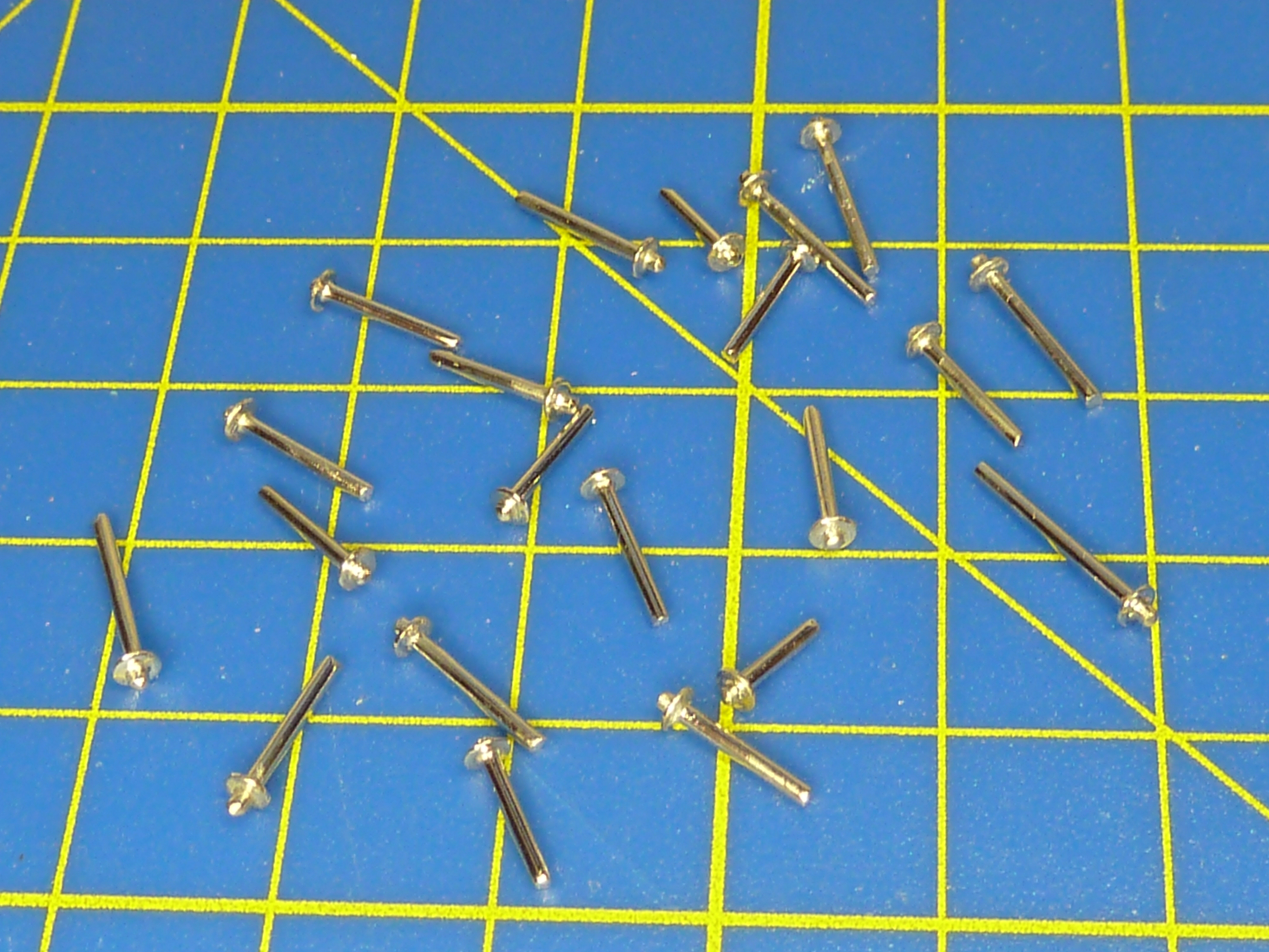
To make the valve stems I soldered some 1 mm washers onto some brass rod.
The small aluminium spacer in the picture has two functions. Firstly it keeps the washer perpendicular to the rod, and secondly it stops the solder running down the rod and leaving you with the whole assembly soldered to the jaws of your pin vice.


Once I’d made all the valve stems they were bright nickel plated.
I’d been musing over what to do about the inlet valve springs. They were conventional coils, and the kit provides you with some nice ones. However, on the real engine the spring is contained within the inlet housing, and so can’t be seen.

It seemed a shame to junk the nice springs in the kit because they would look good, but I breathed deeply and let them go.
To replicate the real installation I drilled out the kit’s inlet housing to allow me to recess one of my valve stems in it.

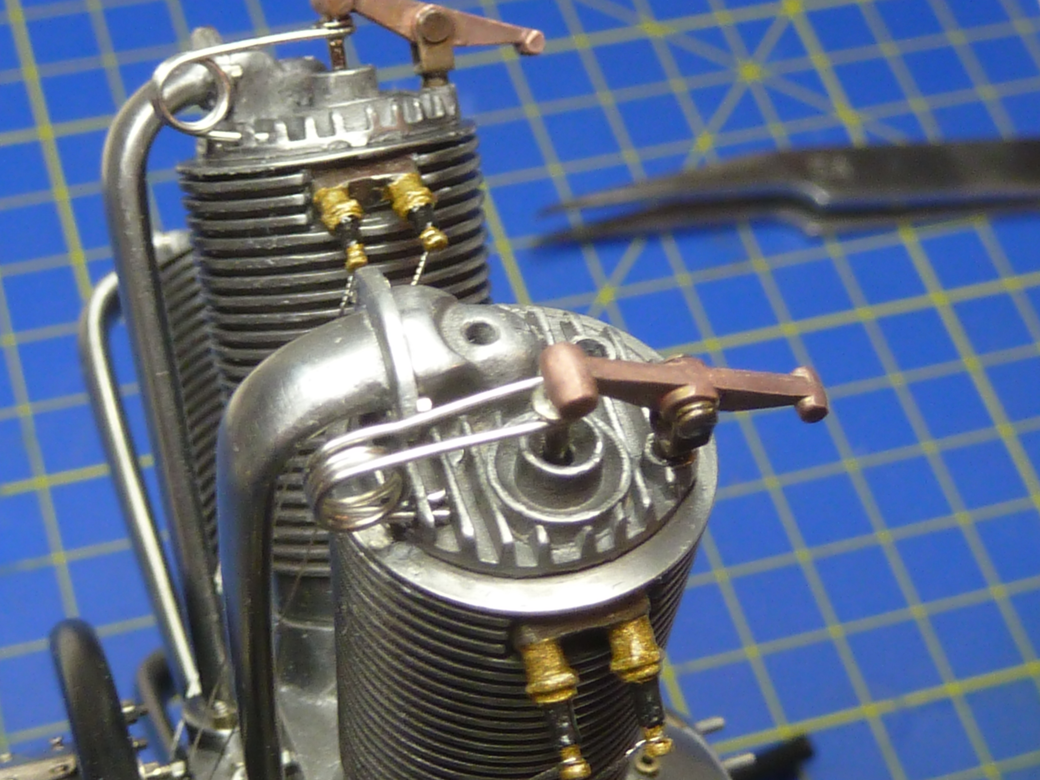
Below you can see the final arrangement.

Then came the fitting of the rockers. I started out with grandiose ideas of setting them in the correct valve positions were no.1 cylinder at top dead centre. I even invested vast sums in a high tech diagram of what I assumed the valve positions would be based on the parts manual information on setting the pushrod lengths.

However, when it came to putting the plan into action I found it wasn’t so easy. Apparently the real rockers had a slightly oval mounting hole which allowed them to move fore and aft slightly as they rocked. The geometry of the arrangement makes this essential if the valve stem is to stay vertical.
Trying to put a such a hole in my rockers was beyond my skills and equipment, and valve stems off vertical would have looked daft, so I reluctantly abandoned the plan.
Having fitted the rockers the final task was to fit the pushrods.
The kit’s offering is quite nice. My biggest complaint is that the rods are brass, and there’s no way they would be in real life. They were actually steel and threaded at each end with lock nuts. That allowed the length of the rods to be adjusted slightly when setting up the engine.
Below is the kit’s version next to the scratch built version I used.

My rod is actually ccomprised of 5 parts. Some 0.7mm nickel silver rod, 1mm nickel silver tube, two tin plated M0.8 nuts drilled out, and a small piece made from 1.5mm brass tube. All the parts had, the by now ubiquitous, ageing applied to them.
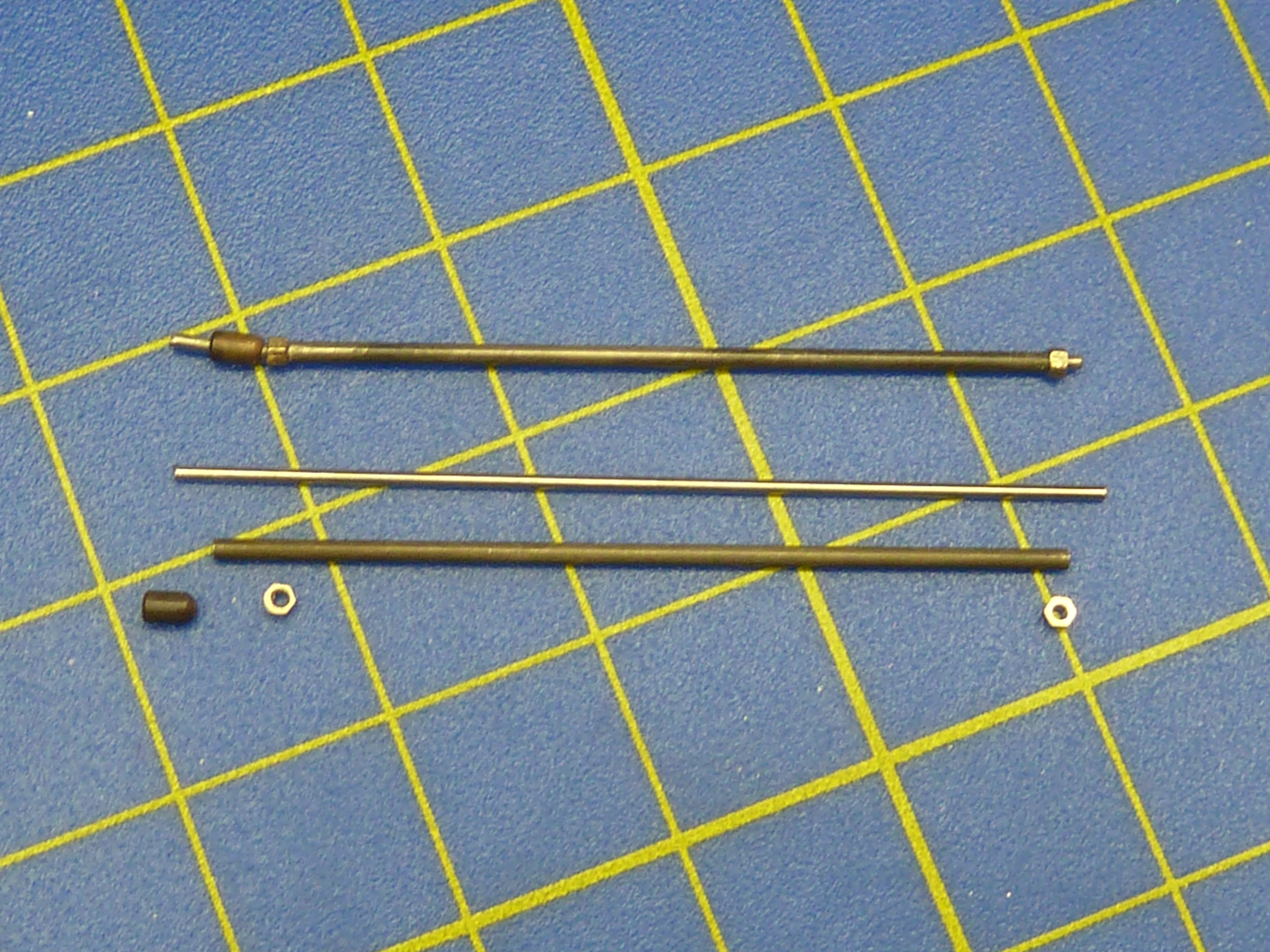
And here is one of my rods next to the kit’s version for comparison.

I think they were worth the effort.
I didn’t abandon the idea of putting the valves in the right positions entirely. If you look closely at the pictures I have set the bottoms of the pushrods in the correct locations. A halfway house solution.

So that was it. Finito.
The model is a nice one to build. Not as sharp in some areas as I’d like, and the castings definitely aren’t as crisp as their injection moulded counterparts. However, as the basis for a significantly detailed model, the kit is way superior.
My model has been finished in an acrylic satin lacquer with the exception of the nose of the crankcase. That didn’t look as good as I’d hoped in the lacquer, so I replaced that with some high quality carnuba wax polish.
Here’s the final model. A full set of photographs are contained in the Gallery section of this blog here.


Now back the boats…

Very interesting !
Is there any chance you would do some of the photoetch on request?
LikeLike
It depends what you want doing. There are companies who specialise in doing that, and, being honest, their quality will probably be much better than I can achieve with home equipment.
For example:
https://modelshop.co.uk/Static/WorkShop/Photo-Etching
email me if you want to discuss it more.
LikeLike
Ah, stunning. I was hoping to pull you up on something, anything, esp those springs, but you did an outstanding job. Unbelievably, I think you are getting even better. That is better than even your other two plastic builds. Absolutely superb.
I built my own rockers and springs on the plastic version, but they didn’t come out this good..
PS: Further to our eMail chats. My test run of the Palmer Aero Chord exact to scale spoked wheels have been made, and they look really good. I was surprised, following our chat, just how strong they are. The concept is proven, so I am now looking at adding the canvas cover holes (2 x 25) and I need to move the valve hole as it’s in the wrong place for the final build.
Keep inspiring me. 🙂
LikeLiked by 1 person
You might want to check out a company here in the U.S. called “RB Productions” they produce screws ,bolts etc, in 1/8 scale and other scales also.
LikeLike
Do you have a link to them? All the searches over here pull up RB Productions in Ireland. They produce lots of photoetch add-ons for aircraft mainly.
LikeLike
Scratch that,my mistake the company is ‘RB Motion’ great selection of nuts,bolts even spark plugs in 1/8 and other scales.
LikeLike
Ah!
I recently discovered them actually, and have a set of their 1:8 sparkplugs on order for another project I’m planning. I wish I’d known about them for the Clerget build.
If the plugs arrive in a reasonable time I might start using them, but it’s been 2 weeks and I’ve heard nothing so far.
LikeLike
Great, good luck hope you receive your parts soon I have never ordered from them before ,but have been on there site for a couple of years. The Clerget build by the way is superb.
LikeLiked by 1 person
Thanks.
LikeLike
Only just come across your blog. Fabulous congratulations!
I’m building the same Camel in 1:16 scale.Saw kit on the net looked
interesting and bought it.MISTAKE!.when it arrived the “museum
quality” was anything but definitely not that.
So being stupid I decided to scratch build.Four years later I am still
building it.
I started with the engine and decided that at 1:16 it was too small to
run [I’m quick like that!} however some elements had to work.
After studying numerose publications I decided the valve gear and rotation
with gun interrupter mechanism wold be possible.
The engine is now finished and when the starter handle is turned the
engine rotates and the valve gear etc. does operate.
At a recent model engineering show it won first place.Even better
at Shuttleworth exhibition it was awarded best in show.
Am now building the rest of the model using full size drawings and lots of photos.
I would put photos on this but d’nt know how .
LikeLiked by 1 person
I don’t think you can leave photos here. I’d run out of storage allocation quickly in people did.
Do you have photos anywhere else? You could post a link, because I’m interested.
LikeLike