
Well, this post has been delayed a bit more than I expected, but I’ve been taking a bit of time off to do the ill thing again. They don’t hand out medical retirement to anyone. You have to work at it constantly. Hence, the modelling activity has dropped off for a while, though I have been able to do some background CAD work for some other modelling projects which may appear in the future.
I’m back at the modelling table now though, so hopefully normal service will be resumed.
In my last post I left it with a hinge that I’d made for the engine bay doors being malformed. Despite trying, the thing wasn’t recoverable and I ended up having to photoetch another. Given the time and faff of making these pieces I think I might invest some money (aka known as spending) and get a professional etching house to produce me an A5 sheet packed with the things. It will save me a lot of time, effort and angst in the future.
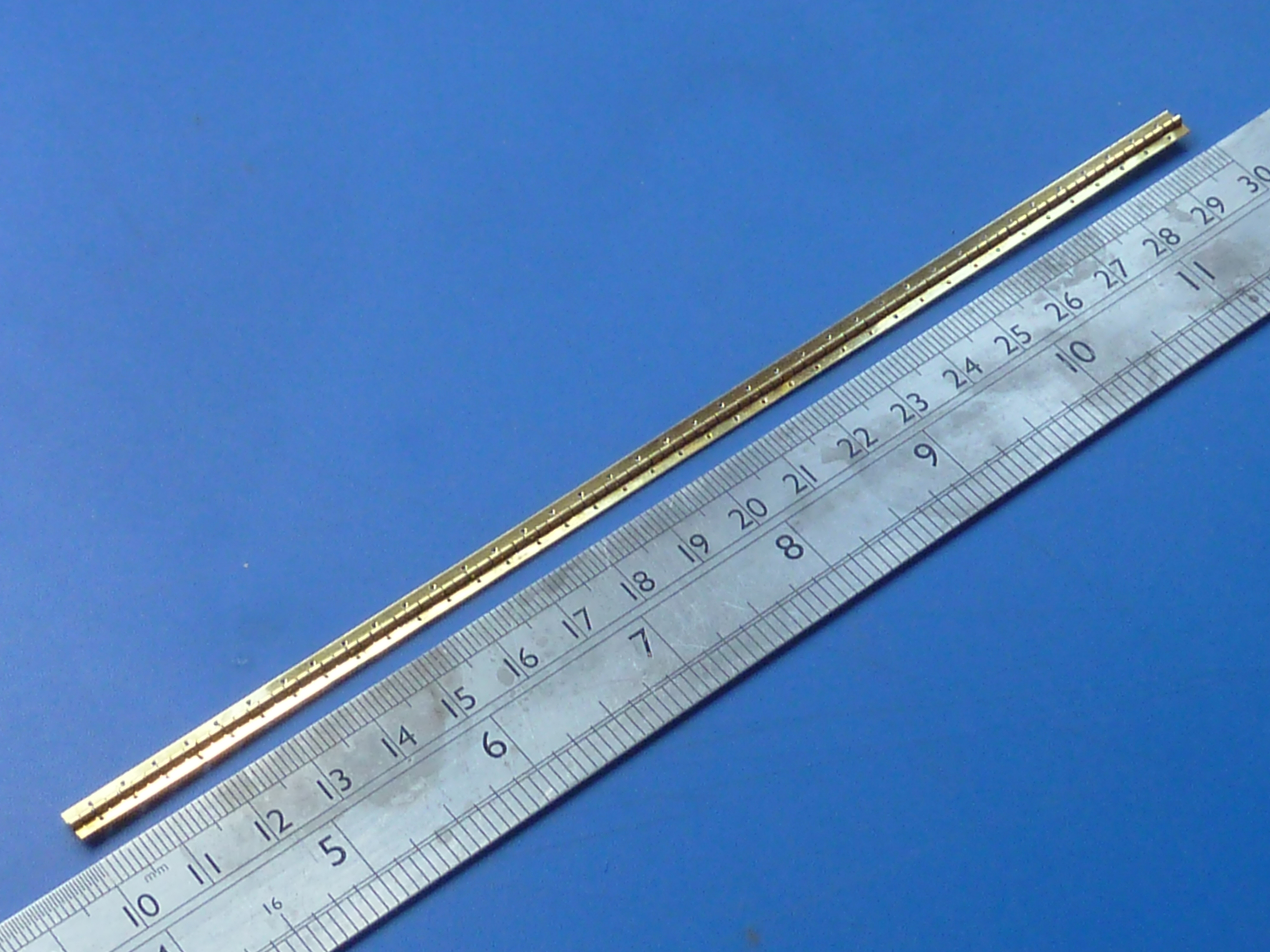
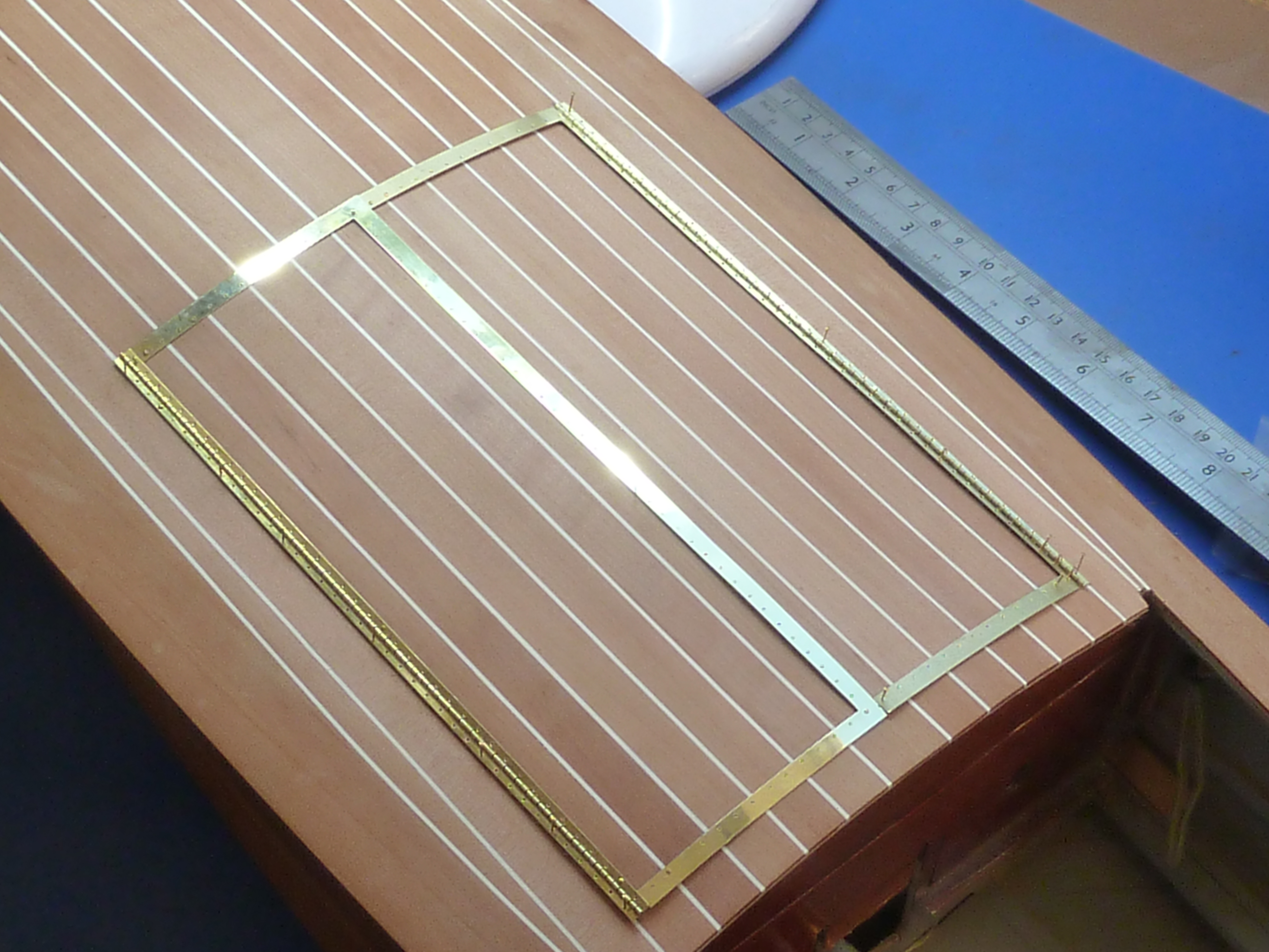

Apart from the bright nickel plating, that is the hinges complete. I’ll plate them when I am doing some other plating work.
Having completed the hinges I moved on to sorting out the engine bay and preparing everything for the installation of the engine and various other components. They won’t actually go in until I have finished sanding down the hull though, because of the dust.
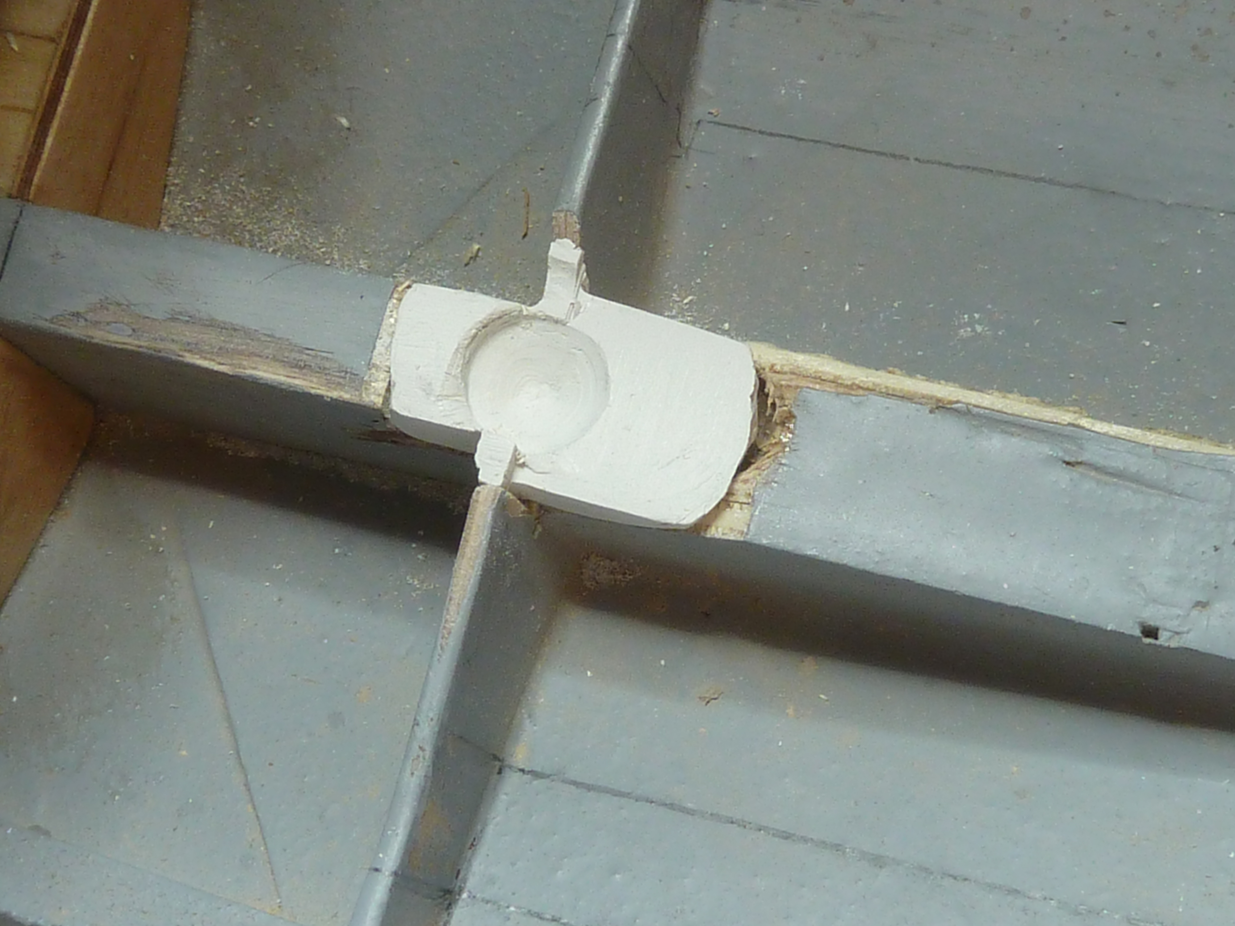
First up was filling the unsightly hole dug out while I was trying to fit the mock-up engine. You won’t actually be able to see this when the engine is in place, but I can’t leave it like it is. It’d irritate me too much.
I mixed up some super fine white Milliput and wrapped it in some clingfilm. Then I pushed it into the hole to be filled and used the mock-up engine to press in the voids required to accommodate it.

Once the Milliput had cured it was removed from the model, unwrapped and filed to the final shape, including adding some relief to the indentations for the engine.

Here it is back in the model. It will eventually be epoxyed in place and any remaining gaps filled with modelling filler.
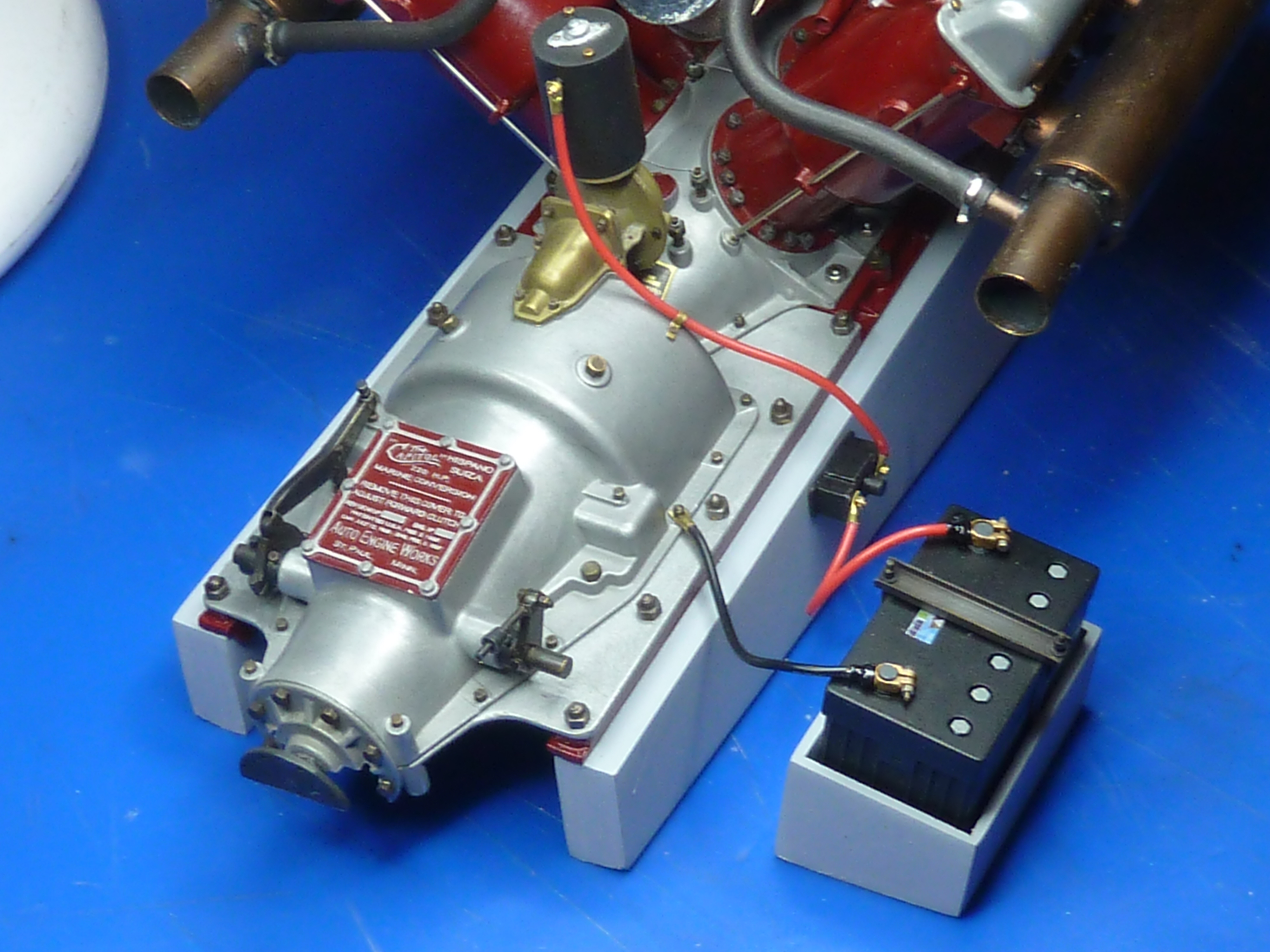
Having painted the engine mounting I’ve finally got around to attaching the engine to it permanently. I had briefly toyed with the idea of actually using the mounting bolts to hold it in place, but trying to get all the studs exactly lined up with the holes was a challenge I ducked.
Instead the engine subframes were glued to the mounting using epoxy glue and the studs glued in afterwards. This also means it is quite easy to get all of the threads showing above the nuts an even length.


With the engine mounted properly on the frame I could get on with finalising some of the smaller installations and connections. Mainly wiring. Below is the starter motor wiring installation. A small ‘solenoid’ has been made from plastic stock.
The oil lines to and from the tank have also been mocked up on the bench. The idea is that I will fit them to the engine prior to it being installed. The pipes can then be fed into the oil tank when the engine is in the model. There is free space within the tank so the length of the pipes won’t be critical.

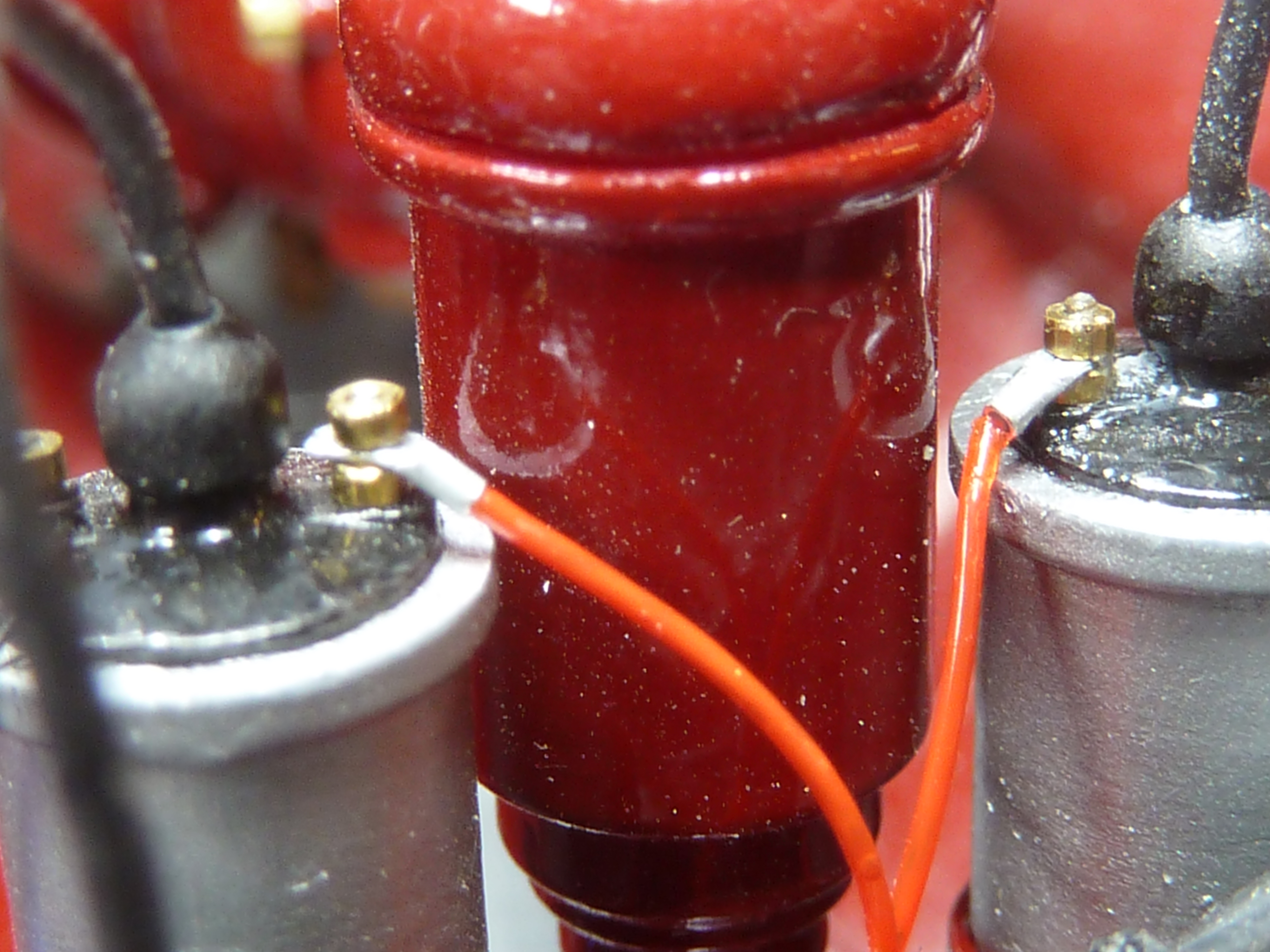
Red fishing line has been used to connect the positive sides of the coils up. The nuts are M0.6.
One other significant development at MBIQ Mansions has been the acquisition of a ‘4k’ resin 3D printer. A Phrozen Sonic Mini 4K to be exact. The 4K refers to the resolution in the XY plane which is 35 microns, or in good old inkjet speak, 722dpi. (1 micron=0.001mm or about 0.00004″)
I think the output from the printer is quite amazing. They are a bit temperamental though, and take some trial and error with settings to get going well. There is however a very helpful forum of other users to refer questions to. I’ve also invested in an Anycubic print washing and curing station, which I would highly recommend as it makes cleaning the prints so much easier. Also invest in lots and lots of Isopropyl Alcohol and kitchen paper towels…
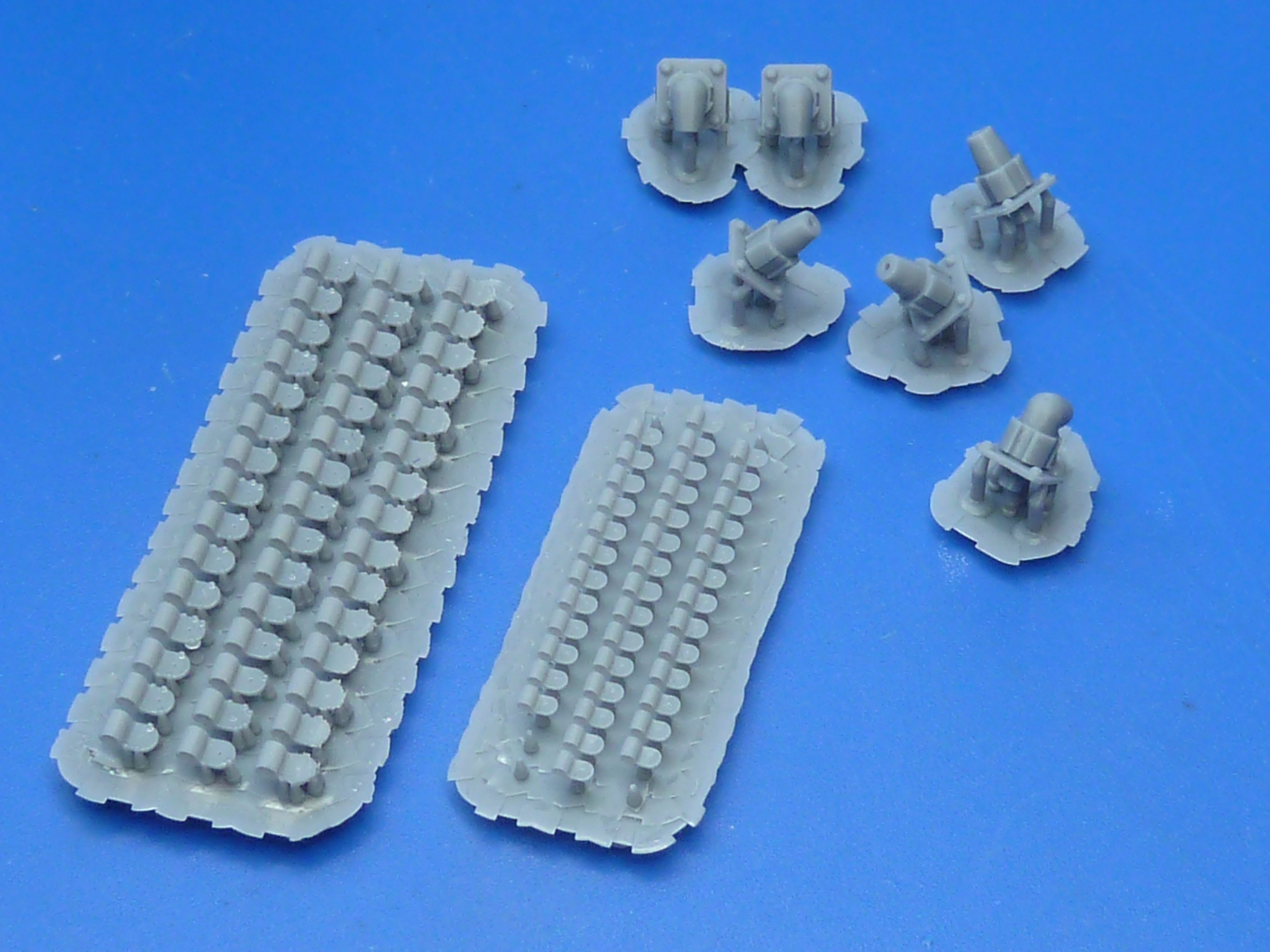
Below is a sample of the printer’s output. Clockwise from top left:
- 35 micron Output from the Phrozen Sonic Mini 4K machine.
- Print at 50 micron resolution from a professional print house .
- British tight-wallet’s preferred stamp.
- Another Phrozen output which was subject to overly aggressive cleaning before being fully cured. Hence the bits of text broken off. Lesson learned!

I’ve used the printer to produce a selection of P-clips and connectors for the wiring looms on the model.
While I was ill I also took the time to knock up a notional wiring diagram for the model to allow me to visualise what wires should be going where. The idea being that the wiring installation should bear some relation to reality when installed.

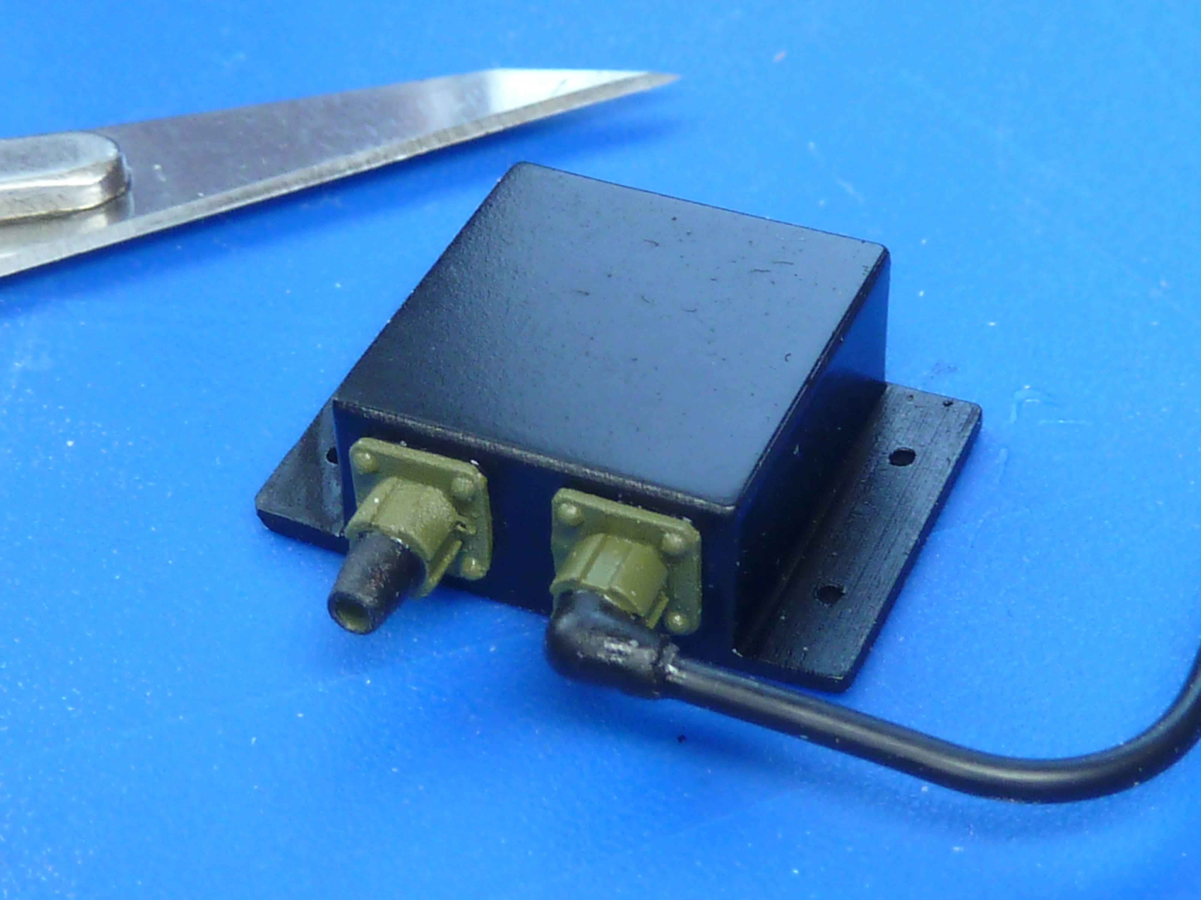
The 3D printer also allowed me to produce some electrical junction boxes in various sizes. For what it is worth, and in the absence of any other information, I’ve gone for a Raychem style of wiring loom with Mil-DTL-38999 connectors. Those were the ones that we used to use on the aircraft and I always thought they looked quite tidy.
Notional wiring loom for the engine. There isn’t much wiring at all on this era of engine though.

The clutch mechanism has also been finalised and a hole drilled in the bulkhead to accommodate it. A piece left over from the Hasegawa Clerget 9F push rods makes a nice simulated rubber grommet. Well, it will when it’s painted black.

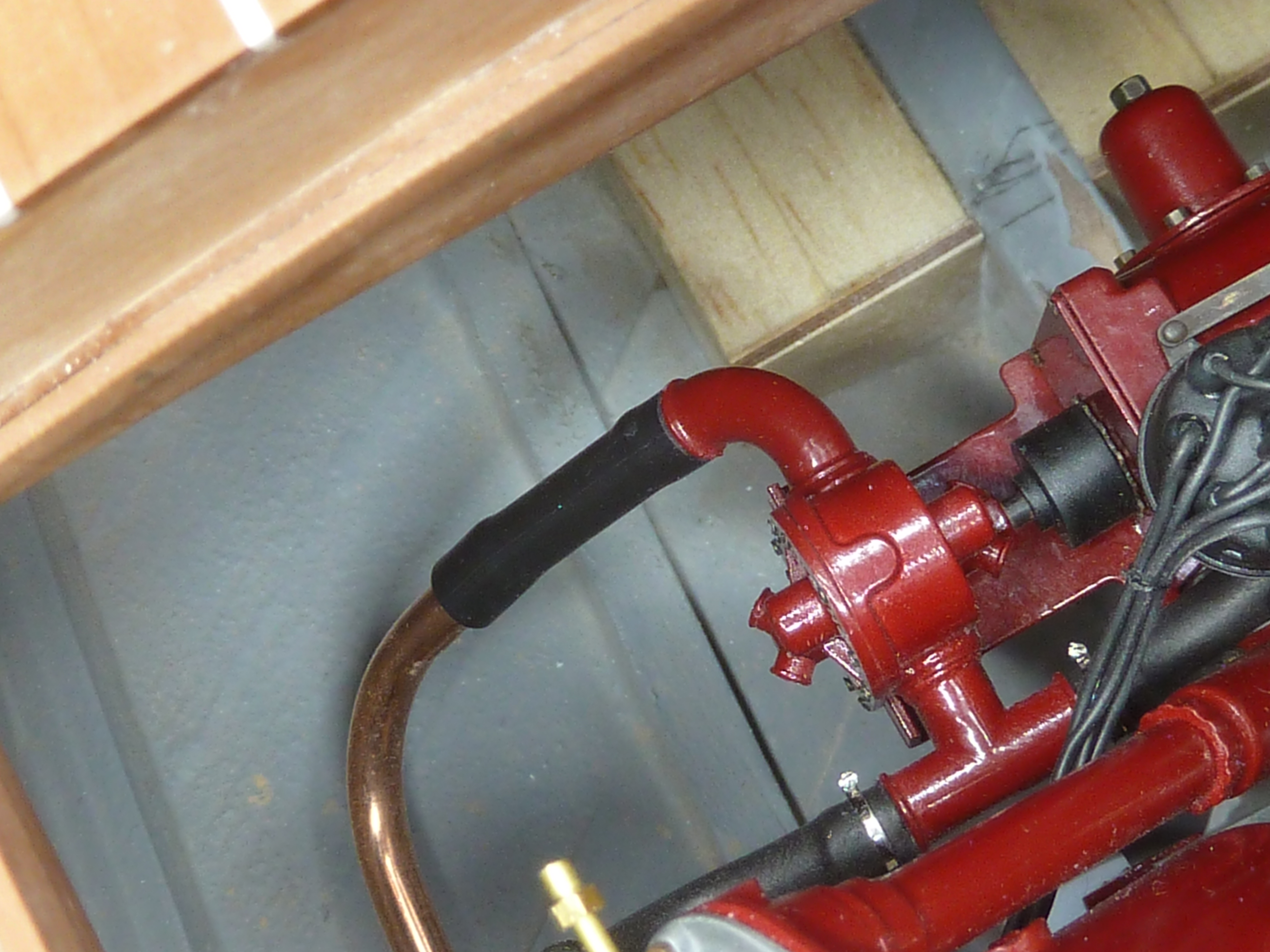
The copper pipe for the main water feed has been manufactured and trial fitted, including saddle clips etc. The connecting pipe to the engine has been deliberately made a little slack on the pipe so that it will be easy to slip over when the engine is finally installed. The jubilee clips have yet to be made.
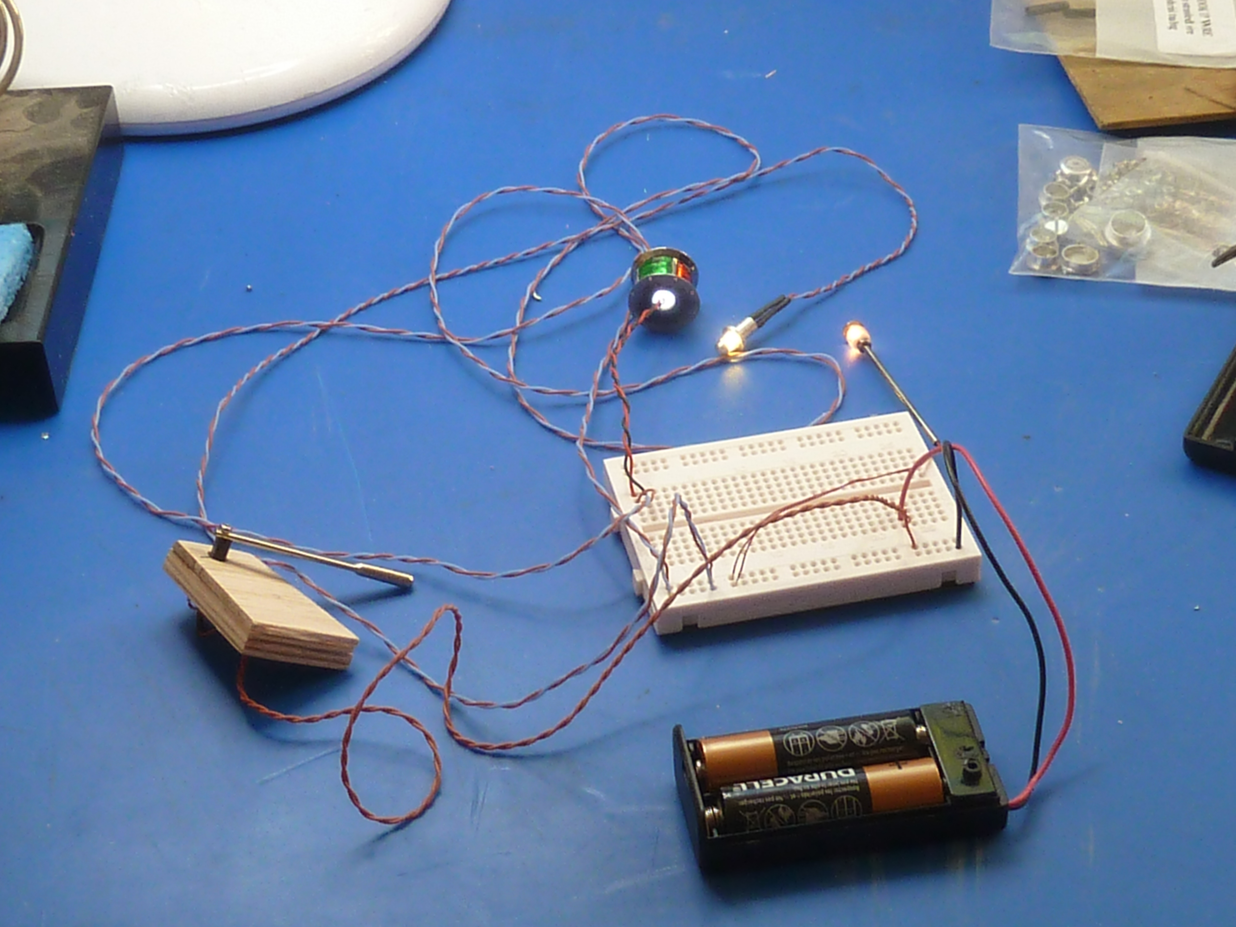
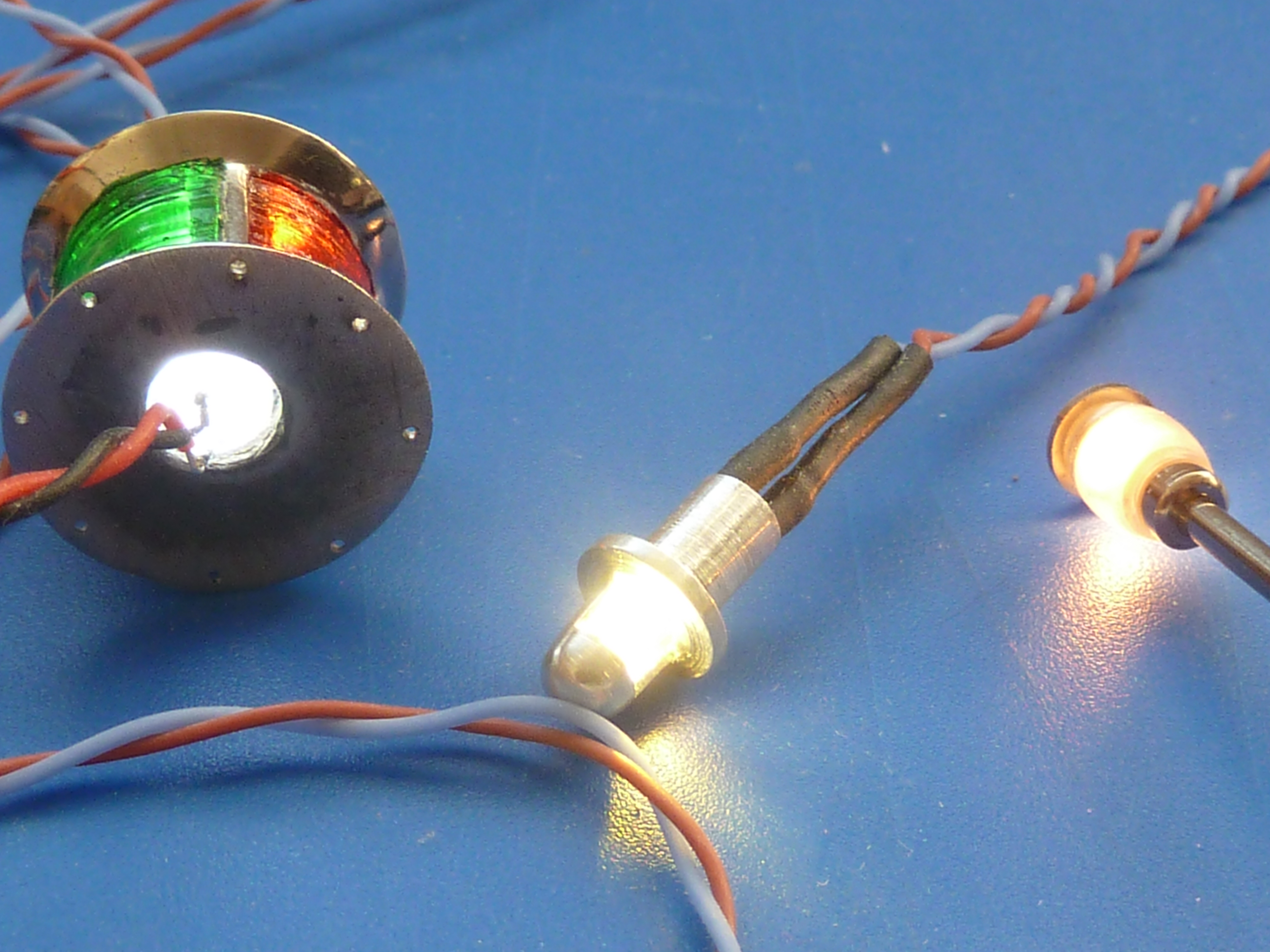
I initially used the wiring provided in the kit to connect up the various lights. However, it was very heavy duty, not that flexible and technically complete overkill. I’ve finally got fed up with it and replaced it with some much smaller gauge PTFE coated wire which is much nicer to work with and a lot more flexible. Just to make sure that the thinner wiring wasn’t going to cause problems with voltage drop I mocked up the wiring on a breadboard before it was installed
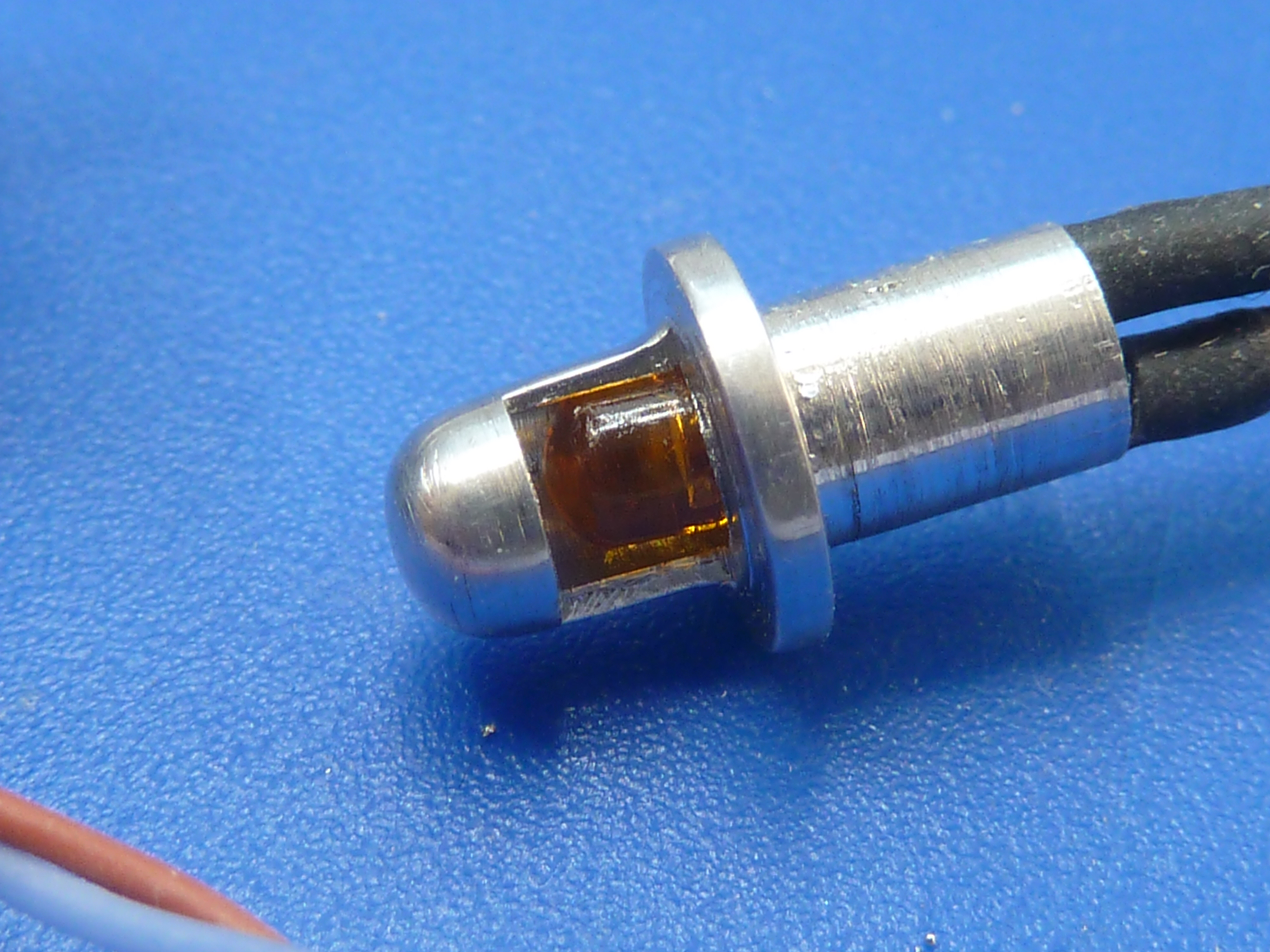
I’ve also replaced the rice bulb lamp in the dashboard with a 3mm LED. These lights won’t be easily replaceable if they fail and the LED should be much more reliable as well as drawing less current. The LED was a hard blue/white light though, so I painted it with some clear orange to give it the same colour temperature as an incandescent bulb.
The 3D printer has really opened up a world of opportunity for me in my modelling. It’s immediately become my goto solution for many bespoke items. It’s much faster for me to bang something out in CAD and print it than make by hand. The results are higher quality too.

Fire extinguisher mounting bracket.

The fire extinguisher was a fun item to make. The 3D print needed a little sanding smooth before painting and a custom decal had to be made, but the final result is quite pleasing. The handle is made from a ready meal tin’s foil. I didn’t think the printer could handle the thinness required.


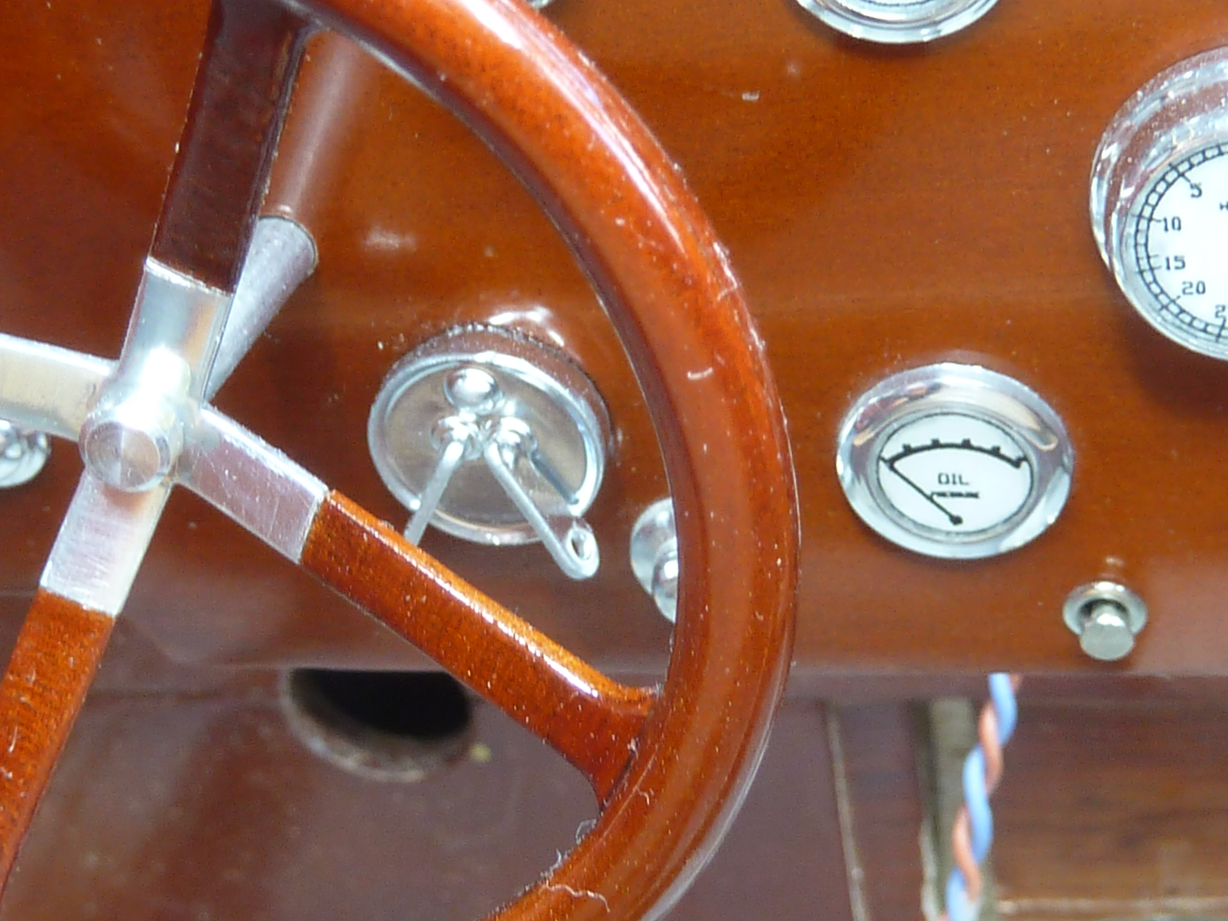
After the break in progress, and to get me back into the groove I went for a quick hit activity and decided to assemble the dashboard. Having done that and trial fitted it in the model I discovered that the steering mounting hole suggested in the Mack kit was a little low for my liking. The steering wheel is quite high in the real boat, but quite low in the model. I marked and drilled a new hole which was where I wanted it, but that did leave me with the problem of the unsightly old hole.
Fortunately the real boat has an additional switch which has been omitted from the kit. I had wondered what I was going to do about it, but it proved a fortuitous way of covering up the unwanted hole in the dash. You can see the switch I mean immediately to the right of the steering column in the photo below.

I’m not at all sure what the switch does or even looks like in detail as the picture above is the only one I have of it. However a PASWAG* design was produced and printed.
*Pure and simple wild arsed guess.

Here it is fitted in the dashboard with the revised steering column hole above left.

Trial fitted in the model with the steering in place. It’s still a bit low, but to change that would require extensive mods.

I did think about trying to cast the switch, but decided that the thin sections were just too much, and I wouldn’t get the alloy to flow in them. However, I have recently come across some quite amazing silver paint which gives one of the most realistic ‘chrome’ finishes I’ve seen.
To be honest it’s not actually paint at all. It’s an ink. Molotow make some Liquid Chrome pens which are themselves quite stunning, and they provide refills for them. The refill ink is easily airbrushable straight from the bottle.
The other major activity I have finally embarked upon is the sanding down of the hull. This is a task that I dislike, quite a bit, but is a vital part of boat building so has to be done. I also have to do it in batches because of the noise it makes, and I don’t get on with noise at all. It’s a slow process but is about 50% done now. Once it’s done that way will be clear to start staining and varnishing the model.

Beyond exquisite!
LikeLiked by 1 person
Good that you are back and showing us all how it should be done.
I have been (sort of) following your progress on the ‘Ms’ as it relates to the Chriscraft Barrell Back I took on a while ago.
It is almost finished but I am stuck with an atrocious set of fittings provided by Dumas, the kit manufacturer, which I will eventually replace; same with the hinges.
Mine is an RC running version, totally overpowered, as I found out when I took her for a ‘shakedown’. During which I made a right turn on a high speed run which resulted in her following momentum in the original direction while pointing in the rudder direction. This resulted in what I can refer to as ‘Barrell rolling a Barrelback’.
She eventually drifted back to me undamaged and as I had done a reasonable job sealing off the interior, there was just a little infiltration.
But what provoked this comment is your coverage of lighting.
I, also, used LED’s, mostly 3mm, set up in three circuits: running, dash and anchor lights which worked from a special servo connection to one of the TX switch channels. By simply toggling the switch, one is taken through a repertoire for each of the circuits; on, off, flashing, pulsing, etc.
I have an iPhone clip but haven’t yet found out how to attach.
Once again, Good to see you’re back.
Best regards. Stay safe.
MW
LikeLiked by 1 person
I’ll admit I laughed out loud at the rudder first antics. 😂
LikeLike
Oh, and the supplied fittings in most kits seem to be awful. I don’t understand why it is so. However, I’ve searched and searched for decent items and they aren’t to be found. The only individual I know who did nice fittings retired a few years ago.
LikeLike
It really is coming along beautifully!
LikeLike
Incredible, amazing work and attention to minute-detail – as always! Beautiful!!
LikeLiked by 1 person
Hiya trouble. Coming along nicely and glad you are making good use of the printer now.
FYI The use of IPA, I have found that Ethynol is both cheaper and cleans better than IPA. Not perfect, none are.
Also, I know you will be pleased to know, and given our little wheel project, I found some rubber resin. I think for tyres and your pipework you may find it very useful. Could save huge amounts of pain. Probably do the whole model in CAD and then print the pipework separately to fit the compartment space. Sorry I didn’t find it before you did Miss Severn
In one of the pics you compare a 50um and 35um build, I assume this is Z axis lift, not X/Y?
She does look a dream. And I am truly amazed at that engine!
https://wanhao.store/products/3d-printing-resin-rubber-resin-1000ml-bottle
LikeLike
It’s 50um vs 35um in all three axes.
The one big advantage of normal pipe vs printed is that it naturally takes the least energy shape. Trying to achieve that in CAD is quite hard.
LikeLike