I mentioned in my last post on the Miss Severn build that I had been filling the time between sanding sessions developing some CAD projects for possible later builds. Here are a few CAD renderings of the models just to give you and idea of what’s been going on at MBIQ Mansions.
Hispano-Suiza 8Ab 180hp direct drive.
This is one of the early versions of this engine. 11.8L and 180hp. It looks very similar to the Wright-Martin H3 engine that I have already featured on this blog, but is actually quite a bit smaller. The Wright-Martin was a licence build of the H-S 8F and was enlarged to 18L and 300hp.
The next is an Hispano-Suiza 8Be which developed 220hp and was one of the last developments of the 11.8L version of this engine. It achieved the extra power by increased compression and higher RPM. In order to keep propeller speeds down the unit was fitted with 0.75:1 reduction gearbox. This was a bit of an achilles heel of these engines as the gearbox was prone to failure and there were several instances of the gearbox and propeller leaving the aircraft before the pilot had finished using them.
Post war the engine featured in a number of racing boats following another marine conversion by Auto Engine Works of St. Paul, Minn. The conversion included updating the magnetos with coil ignition and replacing the reduction gearbox with a bespoke unit featuring a reverse gear. I am developing a converted model as time on the Miss Severn build allows.
Hispano-Suiza 8Be. 220hp with reduction drive.
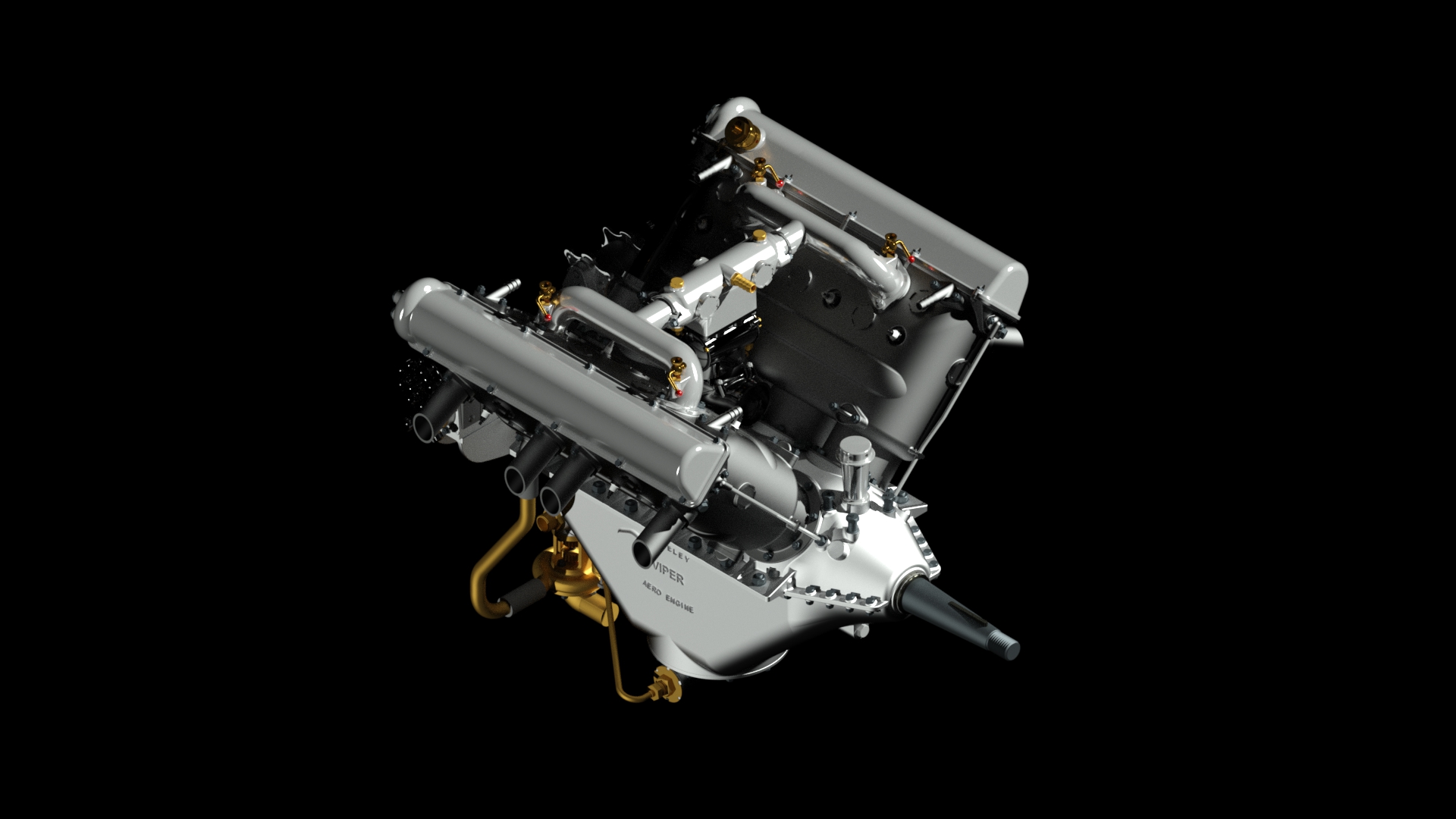
Wolseley Viper 4.A*. 200hp Direct Drive
The next model is a Wolseley Viper 4A*. This engine developed 200hp and was directly driven, thus avoiding the problems of the later H-S 8. The design was a licence build of the Hispano-Suiza 8 engine, but many improvements were introduced during the process and the engine is different from the original version in quite a few areas if you start looking closely.
Wolseley Viper 4A*. A licence build of the Hispano-Suiza 8. 200hp direct drive.
Le Rhone 9C, 80hp Rotary
The final model I’ve been working on is the Rhone 9C engine. Sometimes known as the 80hp Rhone to distinguish it from the later 9J which developed 110hp. The engine was fitted to a number of aircraft, including the Sopwith Pup which is where my interest comes in. I have a long term aim to build a 1:8 Sopwith Pup to go with my Hasegawa Camel model and this will be a key part of it. The work on the main engine is complete, but I haven’t drawn any of the ancillaries yet.*
* Update: The CAD model of the engine is now complete, as you may have deduced from the opening image on this post.
Le Rhone 9C. 80hp.
So, those are some of the background projects bubbling along. All have been designed to be built at 1:8 scale as that is my preferred format. When or whether they will ever appear on here as builds is anyone’s guess!
It’s been a while since my last post, but progress has been a bit slow and there hasn’t been that much to report.
I’m at the hull varnishing and sanding stage, and the noise of sanding is a problem for me. After a few hours of sanding I have to take a couple of days off doing quiet things to recover as the main feature of my illness is a hyper sensitivity to even modest noise levels. Notwithstanding that I have been progressing steadily, and the enforced breaks have allowed me to progress a few other projects in CAD. These will probably appear on here in the future.
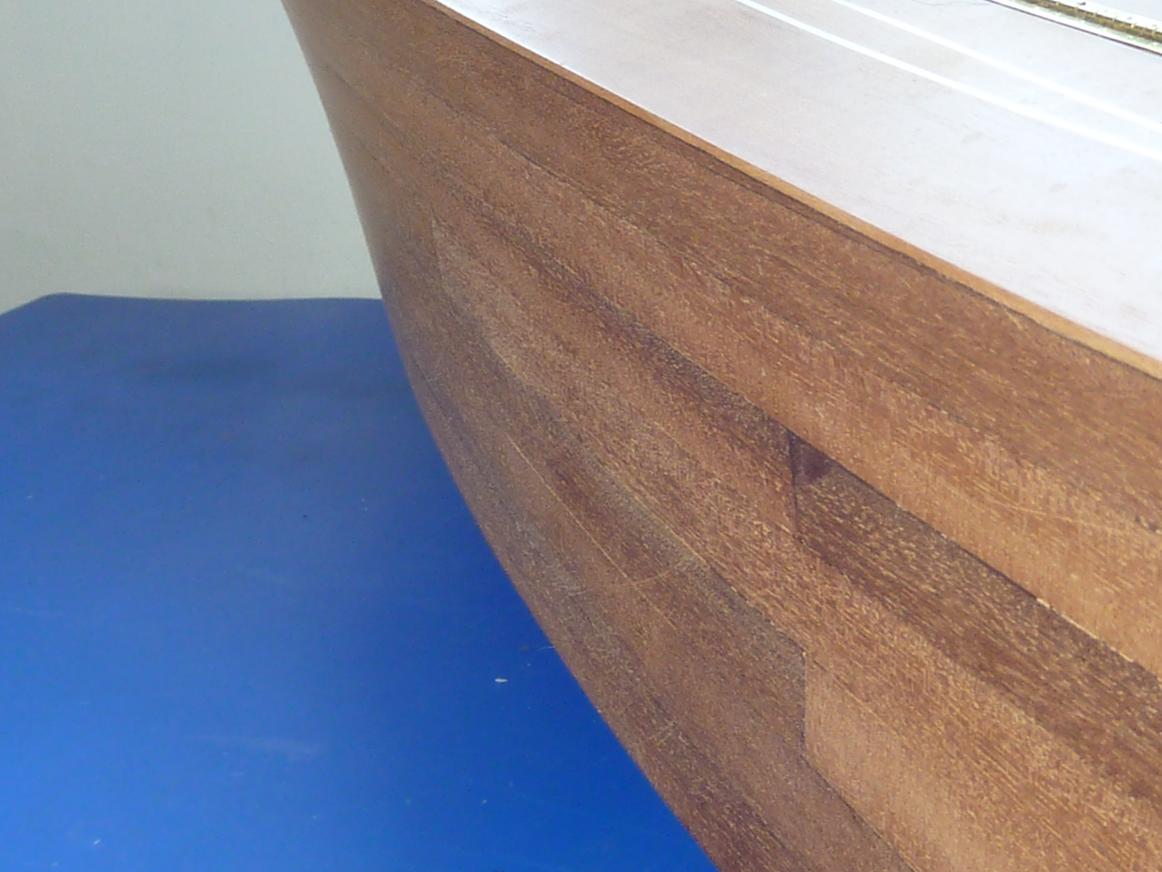
In my last post I left the hull at the bare sanded stage ready for varnishing.
As this boat is going to have gloss black sides with an aquamarine bottom the finish on the sides just has to be smooth. For that reason I’ve chosen to epoxy resin coat it using EasyComposites’ XCR Resin. It’s pretty easy to use and you can recoat in about 40 mins. In fact if you leave it even a few minutes longer than that the subsequent coat suffers badly from “fisheyes” and is very uneven. The short time between coats means that it is easy to build up the thickness for subsequent flatting back. There is an element of self levelling in the resin which leaves a good finish.
Next the dreaded sanding which was undertaken with 120 grit wet/dry paper and finished with 400 grit. It needs to be done wet to avoid clogging of the sandpaper, after a few sessions and breaks I was left with:
It wasn’t all plain sailing though. A few planks sprung loose on the forward starboard side, due to the CA glue not spreading completely under them I suspect, as it was quite a tight curve and the mahogany could’ve done with pre-bending really. When I came to sand the area flat I had to break into virgin wood again to achieve that, which necessitated more coats of resin and sanding..
We got there in the end though.
I had intended to move onto painting, staining and varnishing at this point, but having thought it through I decided to make and trial fit the hull brightwork. Any scuffs and errors could be hidden under the initial coats of paint. It was as well that I did because it suddenly occurred to me that I had completely forgotten the fender rails at the stern. The kit doesn’t have them. It just has the chrome car trim stuck to the side of the hull. Hence, they don’t appear in the instructions.
Cutting the long triangular taper wasn’t the easiest bit of woodwork I’ve ever done as the front section is wafer thin. It stretches about half the length of the actual trim.
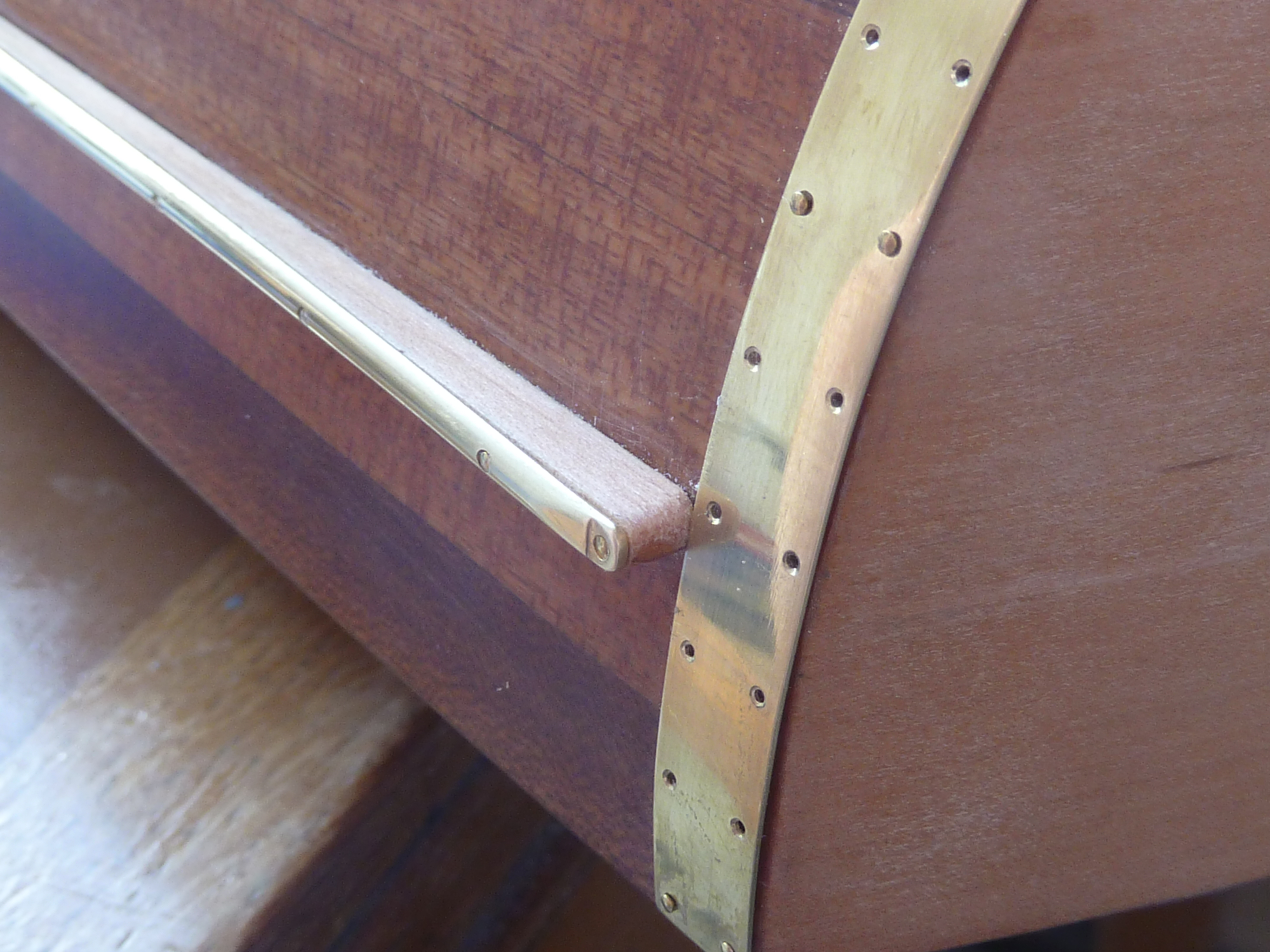
The blue tape is there to provide a reference line as it is easier to work to than one drawn on. The slight ridge of the tape gives you something to push up against when fitting the parts, The rubbing strip itself is 1/8″ half round brass from EKP Supplies in Devon. I’d liked to have obtained something more oval in section, but hours of searching on the net didn’t turn anything up in the scale I needed.
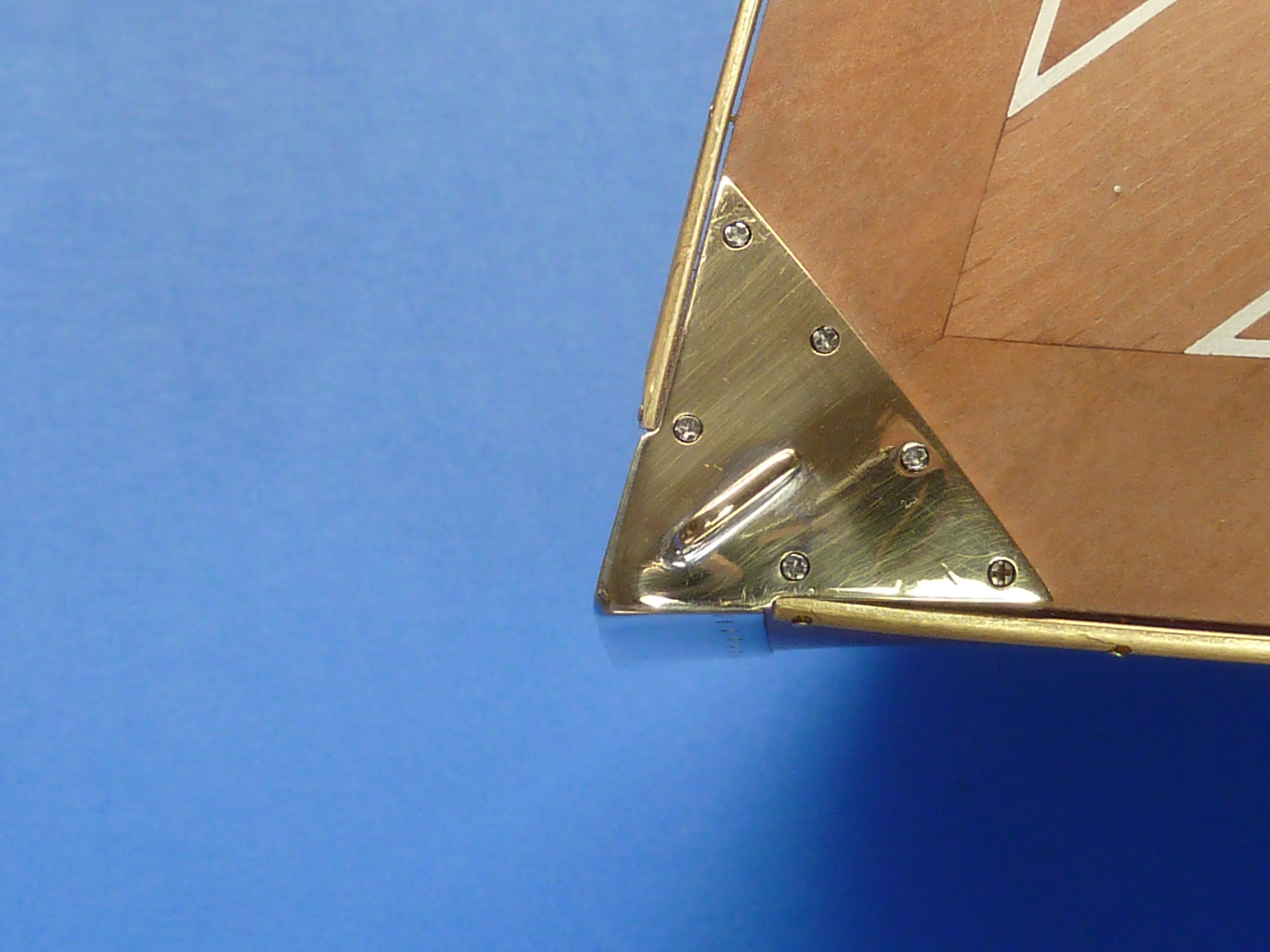
Prior to fitting the strip I made up the protection strips at the edges of the transom. They are an awkward shape to guess, so I put some more of my trusty blue tape on the area, cut the rear profile flush with the transom and used a pair of dividers to scribe a parallel line 8mm (1/3″)from the rear face. the tape was then peeled off and stuck onto some sheet brass as a cutting guide. The method worked well.
When the protection strips were added it gave me a reference for the rearmost edge of the fender strip. After being cut to length the ends of the fender strips were finished off and 0.6mm holes drilled at 20mm (3/4″) intervals. Dull, dull, dull.
Measuring and centre popping the holes in the fender strips. The “Miss Severn” on the cutting mat was the result of practising my gold leaf application, from which I learned that I’m not very good at it.
It was almost inevitable that I’d break a number of the 0.6mm drills as they are quite fragile, but thankfully only one of them actually broke off in the brass. It was however a bit of a sod to get out!
All of the brass items in the pictures have been dry/trial fitted. They will ultimately be bright nickel plated and the pins replaced with faux screws.
Next up was the sheerwater rubbing strip. This is just short of a meter (3’3″) long. It has 51 holes in it. Each hole has to be centre popped, drilled deburred and countersunk. There are two strips. And matching 0.5mm holes need to be drilled in the hull…
So that was 2 days of exciting activity especially when I was down to my last 0.6mm drill with more on order. As I can’t use power tools all the holes were drilled with a manual pin vice. Dull.
They look pretty good though.
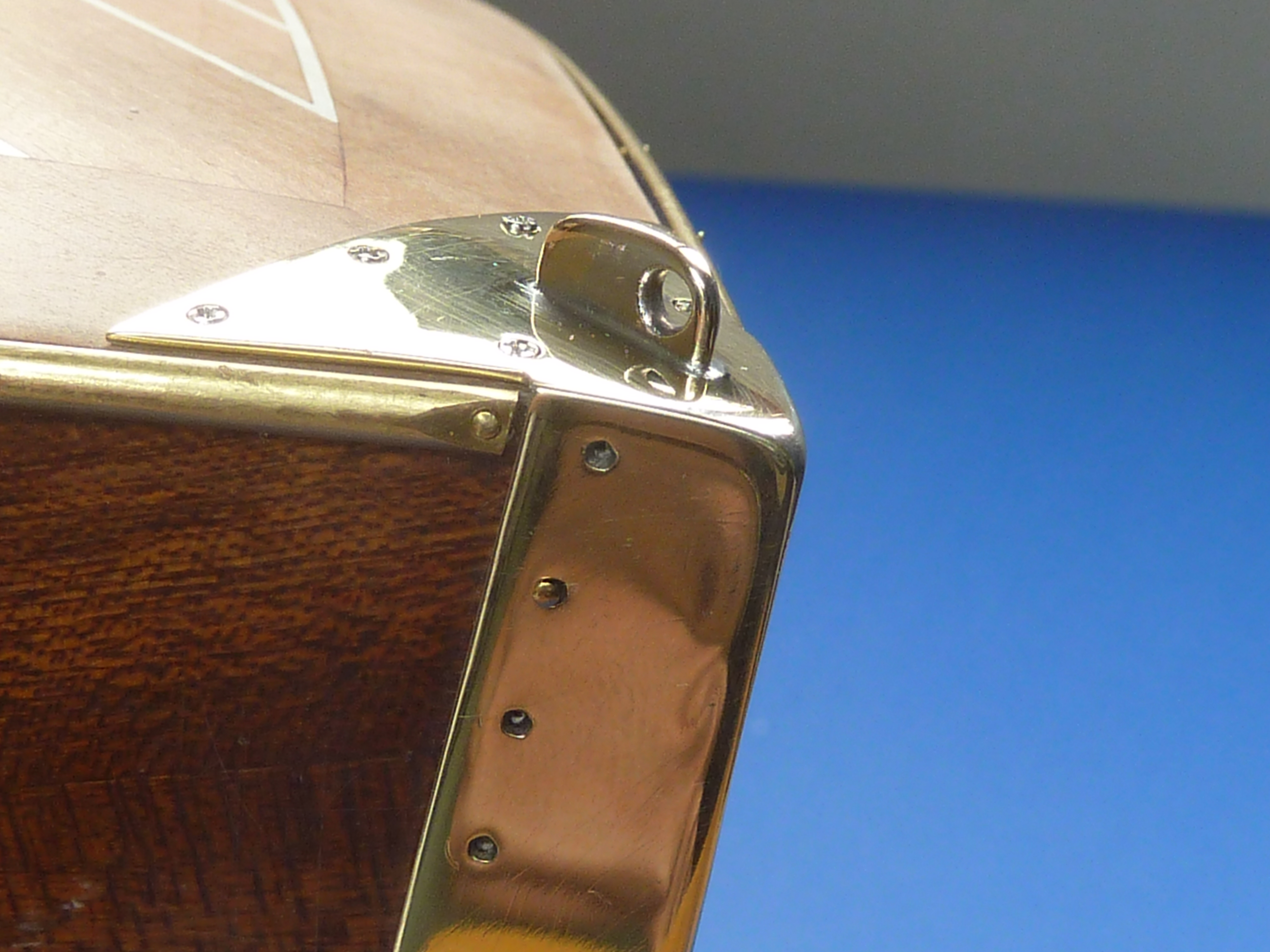
I should’ve mentioned that I also fitted the cutwater to give me the forward reference for the sheerwater strips (80 more holes!). The version in the picture is the Mk.II. Even then the plate at the top wasn’t a stellar fit and was also too thin. The one one the real boat is quite a chunky item.
I glibly decided to remake it in a thicker section. The combination of the thin cutwater sheet and thicker fairlead plate proved a real trial to solder, particularly as I don’t have solders of different melting temps. Having wasted half a day trying to solder it in accurately whilst not unzipping everything else, and failing, I decided that some form of jig was required, One that could withstand my cook’s blowtorch on it.
Whilst mulling over the problem in bed, I recalled I had some Plaster of Paris in the garage that I bought for some long forgotten project and never used…
Next morning I super glued the cutwater together with CA glue and stuffed it in some Plaster de gay Paris and left it to set for a couple of hours. Et voilà! Un soldering jig (anyone remember Miles Kington’s Franglais column in Punch?).
The CA glue was removed from the cutwater and the whole thing soldered up in the rather rough and ready jig. Which worked. It still took a couple of goes to get it good enough though.
The plate still needs a proper polishing to get all the scratches out prior to plating.I know the sheerwater rails aren’t right. they’re only tacked in place for now.
That brings you up to date on the hull work so far.
I have also done a little work on the engine bay doors which will need to be in place for the staining operations if they are to come out the exact same tones. The insides have been stained and varnished, and the cross braces fitted in a contrasting colour of boxwood.
Now I really do need to get onto the staining and painting ops.