
I’ve finally got there. One post more than I thought I’d need, but the two engines are finally complete and a selection of photographs of them added to the galleries under the drop down menus at the top of the page.
There wasn’t much left to finish them really. The main activity required was the completion of the coolant hoses, and the installation of the exhaust studs.
As before the hoses were made up of three parts.
- A wire core to make sure they keep the right shape during heating.
- A polystyrene inner tube to give them the right diameter.
- An outer sheath of black heat shrink tubing to give a true rubber appearance and thin wall thickness at the ends.

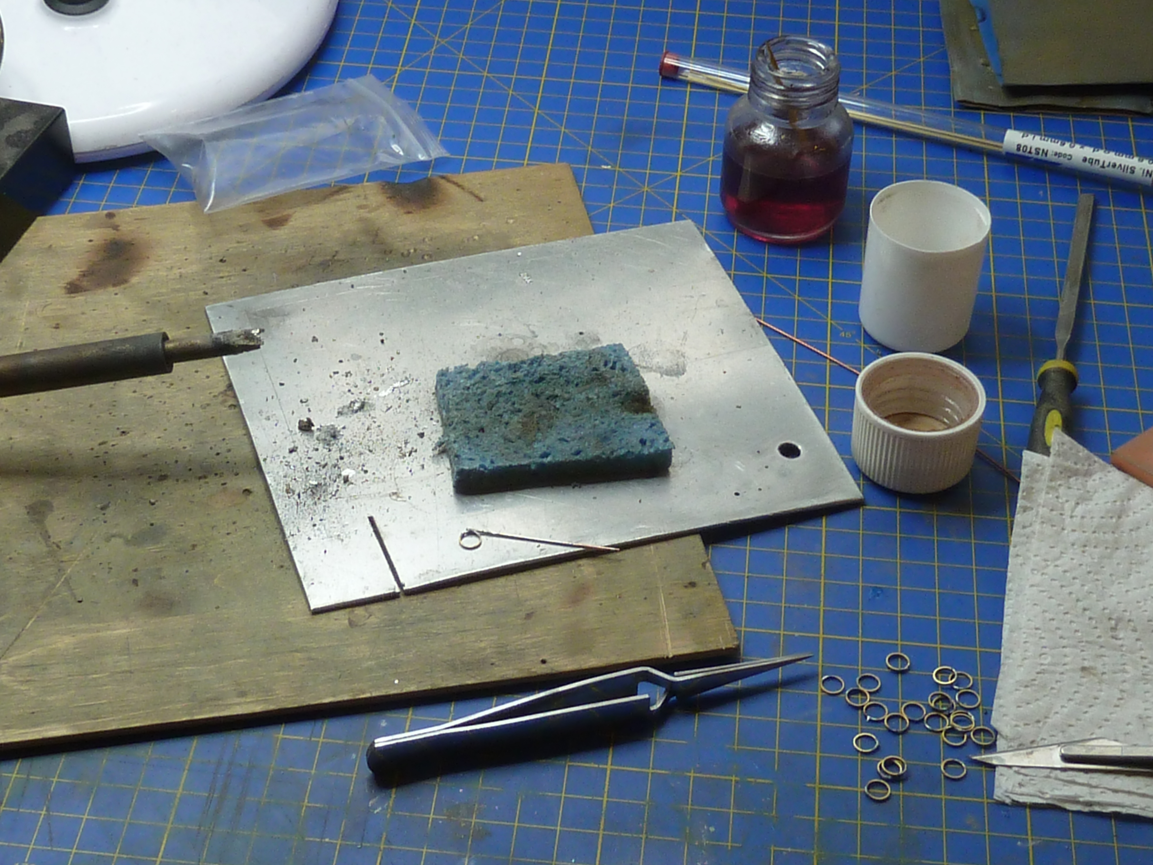
Each hose was run to the model then measured up. A final version was then made from fresh materials, as I’ve found it is necessary to partially shrink the outer onto the assembly then bend it to shape. Once that’s complete you can remove any wrinkles in the outer by completing the shrinking operation. If you try to slide the heat shrink over a bent inner, like the one in the picture below, the inner wall of the curve wrinkles to an extent that can’t be remove entirely during the heat shrinking process.

The process is a bit laborious to be honest and caused me quite a bit of grief. In hindsight it would’ve been a much simpler option if I’d done it in conjunction with fitting the exhausts rather than after. As it was some choice epithets might have been uttered during the operation.


The hoses on the burgundy engine were by far the worst to do as the arrangement is more complex than on the black one because of the location of the water pump.
Other minor work included fitting the cylinder priming pipework on the top of the burgundy engine. For some reason this was quite difficult, which was a surprise as it was relatively straightforward on the black one and they are supposedly identical. Probably just an off day at the modelling desk.
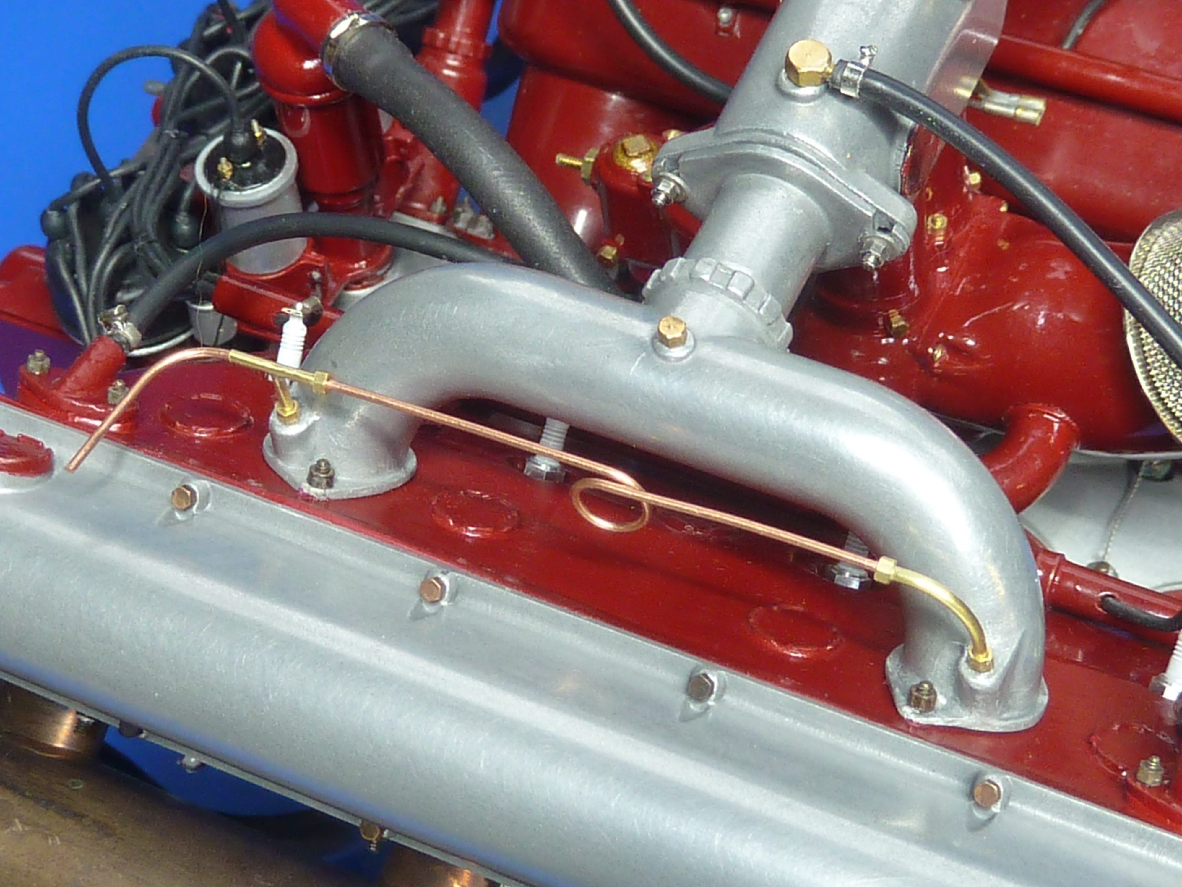
The coolant hoses also required the making of several batches of faux jubilee clips. These are fairly simple but take time. An appropriately sized tube is cut into thin sections and some thin (0.8mm OD) tube soldered to the rim. The whole assemble is bright nickel plated. As a final flourish a brass pin which has had its head slotted and then been bright nickel plated is glued into the cross tube to look like the screw mechanism.

The very last operation was to add the exhaust mounting studs. These are just glued on and have no physical function. They were made from Some M1 threaded rod with M1.0 brass nuts glued in place. The whole affair was then burnished to make them dark. Tedious and unexciting work. 32 required per engine.

If I were make another of these models I’d approach the exhausts in quite a different way I think. I’d keep the flanges separate from the exhausts themselves, which I have seen on some engines. That would make getting everything aligned much, much easier and would allow the studs to be actually glued into the block.
That’s it for these engines then. A lot of fun to make, but much more involved than I thought it would be. I’d secretly envisaged it taking about half the time it has. I wasted a lot of time and effort though trying to master white metal casting of the aluminium parts before admitting defeat and using the cold casting technique. Now that I know what I’m doing and have all of the moulds to hand I think I could build another engine in 250 – 300 hours. I might even do that as I’d like to have an unmodified aviation version too. They’re not cheap though when you add up the costs of all the nuts and bolts.
Here are some pictures of the finished models. There are a few more in the gallery pages too.


There is a CAD version of the aviation engine ready to go. I just need to get the exhausts printed off…


Nailed it… stunning. Why not do a SE5a to go with the engine, and your Camel F1 and Dr1?
LikeLiked by 1 person
It’s the 18L (8F) version, not the 11.7L (8A/B). It’s quite different in a lot of dimensions. I think it would be too large to fit the SE5a.
I might one day go back and do an 8B. A lot of the CAD would read across. It’d need completely new water jackets and sump. I’m not sure about the block. That might just need the cylinder interfaces tweaking.
I’d also like to do a Rolls-Royce Meteor engine as that has made its way into a lot of post WW2 boats. Oh, I have a vague idea of a 1930s Bentley engine. Either the 6L or the 4.5L…
There aren’t enough hours in the day!
LikeLike
Ah, sounds like you are getting a taste for a topic. Have to say it’s a good one. The rotor and now these babies all look fantastic. When I made mine and put them in my cabinet, regardless of quality they look so good, take up so little room, even big scale… Sounds like you also need a trip to The IWM in London… They have rows of engines stacked up.
LikeLiked by 1 person
I wish. I’m housebound, so it’s Internet and books for me.
LikeLike
These are absolutely stunning especially when you think of the process they have gone through. Well done!
LikeLiked by 1 person
Sorry, yes, forgot that.
It is a lovely collection of ramshackle engines from the first to more modern jets and turbines. Inc the Hissi. If I can find any pics I’ll send.
LikeLike
A work of love! It is very touching actually.
LikeLike
I really had to look closely at your finished model to see if it was not a photo of the actual motor. Astounding.!!
Sorry you are homebound. The good news is that you have time to make truly remarkable creations, even though illness is a high price to pay. The nice thing is that you share them with a very appreciated audience.
I am building a 1/8th model of Baby Bootlegger & the Hisso would be so correct for the boat.. Would you be persuaded to make the 3d printed parts so I could make up one for my boat model? Cost?
I live in Canada & newly retired so I can devote more time to my boatbuilding hobby in the winter months.
Cheers!
John Marck
LikeLiked by 1 person
Oddly enough, I have a longterm aim of building a Baby Bootlegger model one day and that is partly why I chose the Hisso as a subject. That, and the availability of source info.
LikeLike
Baby Bootlegger will be a great model to build ! I have built Miss ACBS ( Miss Severn hull design ) as ” Meteor 5″ with a different deck style & interior & painted hull to reflect the difference between the boats. Mark Mason found & restored “Meteor 5″ &” Baby Bootlegger” , & the rest is history.
In lieu of making the 3d printed parts, is there a computer program available to print the parts of the Hisso?
LikeLiked by 2 people
Do you have a 3D printer? For this type of work, it needs to be able to do fine detail so has to be a resin printer, and the better quality the better.
3D printers work on STL files created via an export from any 3D graphics sw. Blender, Sketchup, CWX, CWS, there are many….
You can make your own with a Pi 3 or 4, LCD screen, HDMI board, motor, end stop, controller board, power supply, UV Light (right fq), loads of fans and the actual bit n bobs of the casing etc. Run on nanoDLP…
LikeLike