
Well hopefully this will be one of the last posts on these engines and I’ll soon be able to get back to completing the Miss Severn and Chris Craft models. The engine diversion has been much longer than I anticipated and I’ve had to remind myself a few times that the actual aim is to build the boat model, of which the engine is only a part.
If you recall from my previous post, I was messing about with cooling pipes as the size I had intended to fit looked too large on the model.

I spent most of a day rifling through my odds and ends boxes trying to find something that would do the job. Attempting to satisfy the need for a thin wall thickness and small diameter was not easy, especially as some of the pipes have to go in quite tight curves. Thin wall and tight curves equals collapsed pipe. I’d also already had problems with the pipes fitted to the black engine putting too much strain on the mounting points and pulling them off, so whatever the solution was it had to also be low stress.
Hence, I really needed the pipes to be pre-formed to shape as well.
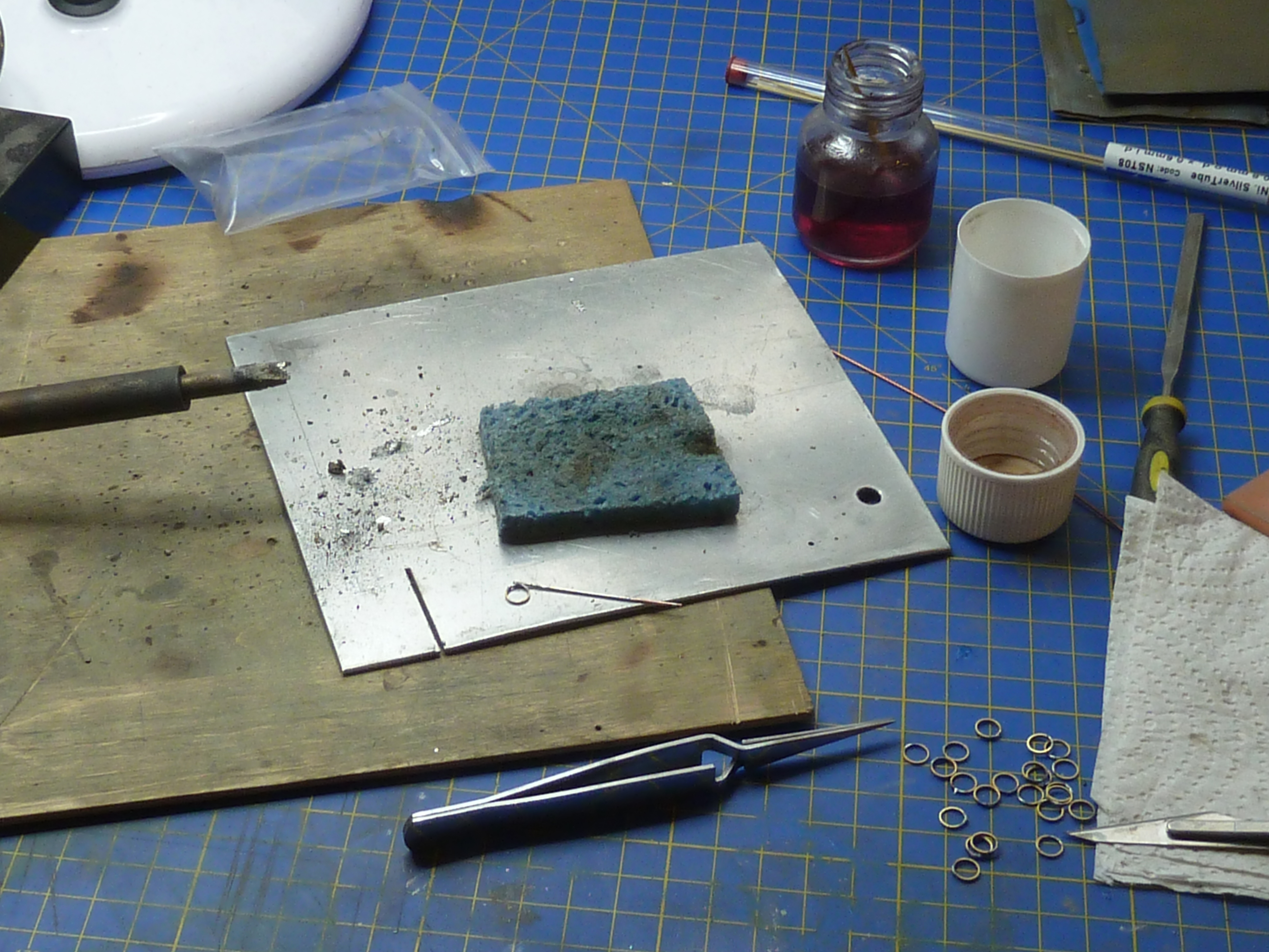
After a day of testing various ideas I gradually homed in on a compound solution. The pipe run was formed from some polystyrene tube with a copper wire core.

Heating the whole affair allowed me to bend it to the desired shape, and the copper core made sure it held that shape as it cooled. It also meant there was no chance of the tube collapsing in tight bends.
Once formed black heatshrink was slipped over the whole assembly and shrunk on with a heat gun. To allow the pipe to mate to the parts already on the engine I placed another, slightly larger, tube over the end of the copper core to give me a slightly flared end. That was then removed. Obviously you need to use heatshrink without glue for this process.
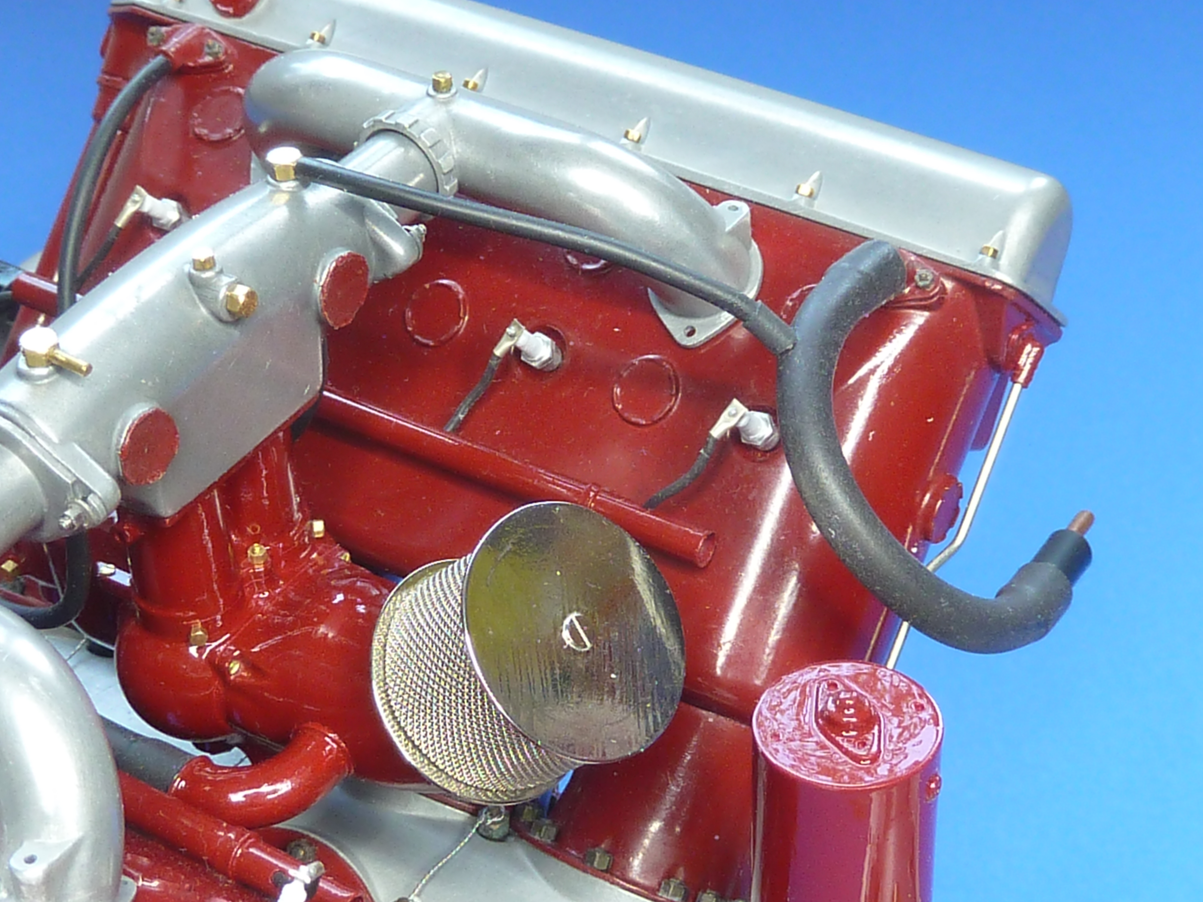
Below is a picture of the first pipe made this way. It is actually the crankcase vent connection to the carb inlet rather than part of the cooling system.

I’ve also made a proof of concept prototype of the cooling outlet into the exhausts (the cooling system is a total loss/open loop design as are most boats, and the water is dumped overboard using the exhausts). I won’t be able to finalise that part of the design until the exhausts are fitted.
Having finally resolved the piping conundrum I could get down to making all of the jubilee clips I’d need. They are just some 0.8mm copper tube soldered to a thin ring cut from brass tube.
The assembly is then cleaned and bright nickel plated, and as a final flourish, a slotted 0.6mm panel pin is glued in the cross tube to simulate the adjustment screw.
After a couple of days work I found myself in possession of…

Which doesn’t look much for the effort required. Ho-hum… onward and upward.
As a quick side activity while various parts were electrocleaning or plating, I made some more of the ID plates for the engine. One for the side of the sump and one for the carb. These were made as before: a custom decal applied to brass or aluminium sheet.


There is another ‘Simplex’ label I’ve seen mounted at the back of the sump, but I’m not sure it was fitted when the ‘Hispano-Suiza Licence Built’ was fitted on the side, so I haven’t added that (yet). More research needed.
As the burgundy engine had now reached the stage where it needed to be mated with its gearbox on the subframe I needed a second build stand that would take that whole assembly. Rather than build another gash one out of plastic I decided to swipe the one holding the black engine as that was already a bit battered from constant handling.
As the black engine was not far from completion I decided to transfer that to its final presentation stand which was made out of square section brass tube.
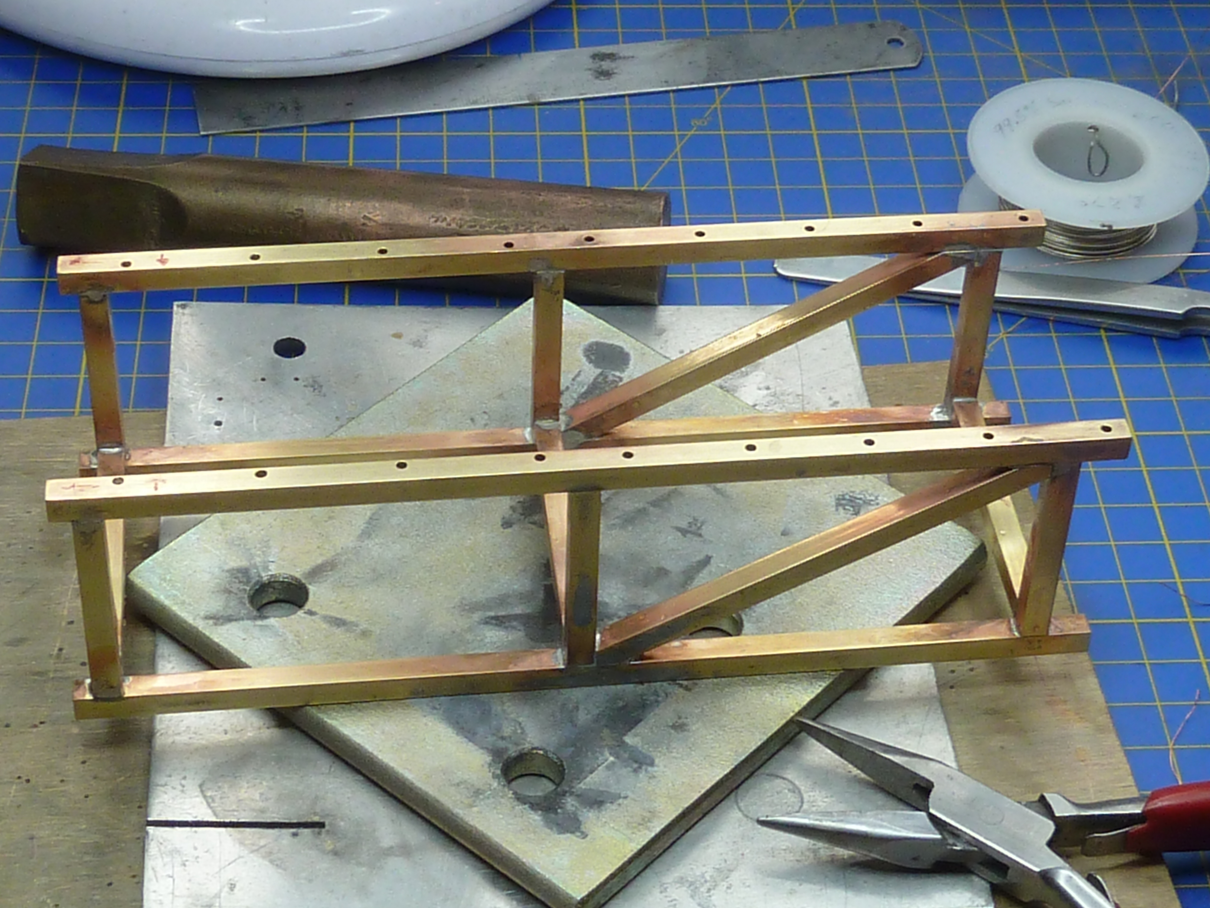
The stand was painted with an etch primer, then finished in satin black from a rattle can.
Fitting the correct mounting bolts for the engine was a barrel of laughs. They are really quite hard to get at. The first one (of 14) took 45 minutes. Oh, deep joy…
Things did speed up quite a bit after I fashioned a few wooden wedges to hold bolts in place while nuts were fitted, but the job did severely test my patience. It really needs three 1/8th scale hands, especially as you are desperately trying not to scratch the castings or nuts in the process.

Having got both engines mounted on their subframes I could move on to finishing the detailing of the gearboxes. Key to that was installing the starter motors. I had previously cold cast the parts in aluminium, but some parts were definitely brass judging from pictures, so I remade them in cold cast brass.

The parts were then fitted in place and the detailing nuts and boots added.

The burgundy engine’s gearbox has a cut-out at the rear to allow it to fit around the stuffing box already installed in Miss Severn. The rear of the gearbox will actually be hidden deep in the bowels of the model and the cut-out invisible.

Having sorted the piping problems and got both engines mated to their gearboxes I could move on to the exhausts. These were water cooled and appear to be specific to each installation. I’ve certainly never seen a ‘common’ design around.
The big difficulty with the exhausts was the oval header pipes. One of the distinctive differences between the Hispano-Suiza 8B engines in the SE5a, Spad etc. and the 8F is the change from nice, simple, easy to find circular pipe, to rocking-horsesque oval on the latter.
I did try just squeezing some round pipe in the vice, but found that gave me a race track shape rather than a true oval. In the end I decided to make some custom formers using my 3D printer. The PLA plastic it uses it quite tough and strong enough to form annealed thin wall brass tube.
I calculated the size of tube required to form the oval based on the assumption that they’d have common circumferences and it came out at 7.1mm diameter. So, 7mm diameter tube it was. A former design was quickly knocked up in CAD and printed. After a few trials revealed that the mathematically ideal solution wasn’t in real life, so the design was slightly tweaked and reprinted. Quick to type, but that all consumed another day’s work.

Using the slightly undersized pipe to form the headers did mean that all the lovely mounting flanges that I’d photoetched previously were now a slack fit and needed to be remade. So a tweaked etch mask and more etching…
And somewhat to my surprise it all fitted.
Here is one of the exhausts mocked-up on the black engine.


The only remaining question is how to finish the exhausts. I’d always assumed they’d be nickel plated in some way. To that end I knocked up a test piece to gauge which looked best, the options being:
- Bright nickel plated on a polished finish.
- Bright nickel plated on a brushed finish.
- Dull nickel plated on a polished finish.
- Dull nickel plated on a brushed finish.
The bright nickel on brushed looked awful and was right out. The ‘chrome’ finish was OK, but not really in scale.

There wasn’t much to choose between the two dull finishes, though dull on brushed had the edge.
Having mocked-up up the exhausts on the engine, the natural copper finish was actually quite nice on it’s own, and I have seen at least one boat restoration from this era where welded copper exhausts were fitted. Cost was not mentioned!
It was suggested that an aged natural copper finish might look good, so I’ve decided to give that a go. If it doesn’t work out I can always just clean things up and nickel plate anyway. I’ll let you know next time…
I’ve also been musing over how to install the exhausts in the actual Miss Severn model. Not surprisingly the faux exhausts in the model don’t line up exactly with the engine’s, and a small translation section is required (the S-bend in the CAD rendering below).

Based on my aircraft experience I also assume that the exhaust system would have some sort of flexible anti-vibration part to isolate it from the hull and it seemed logical to combine the two.
At the moment I’m working on the idea of using some braided pipe to form the link piece. I’m not 100% convinced yet though as the braid is perhaps a little overscale.

The other main activity that is ongoing to finish the models concerns the clutch mechanism. I have very few pictures of this and there has been a lot of supposition going on in designing it (that it’s the clutch is supposition for what it’s worth). In fact it took me about an hour of staring at the few pictures I have to work out how the thing functioned at all. It’s one of those things where it’s blindingly obvious when you know what you are looking at, but quite opaque otherwise.
Whatever, the design is complete and just needs to be made. I’m not certain how I’ll do that yet, but photoetch is top of my list.

Here are a couple of pictures of the engine models as they stand at the moment.


These engine models are no longer in the realm of modelmaking, they really are art. Simply incredible. Must be glorious to actually look at them in person! Cheers!
LikeLike
Thank you.
LikeLike
Kelly Harris is Eric Marshall Green. Cheers!
>
LikeLiked by 1 person
Huh ha. Brightened my day. Stunning. I wanted to start them up and get them running.
LikeLiked by 1 person
I just want to get them finished.
LikeLike
I can see that. Just like me and this HGFHKGJKHJKLH printer!
TBH you say it is only one aspect of the boat, but actually it is the largest, most complex and vital, bar hull and deck. So well worth the effort. I just wanted to know if it could power my car!
LikeLike