
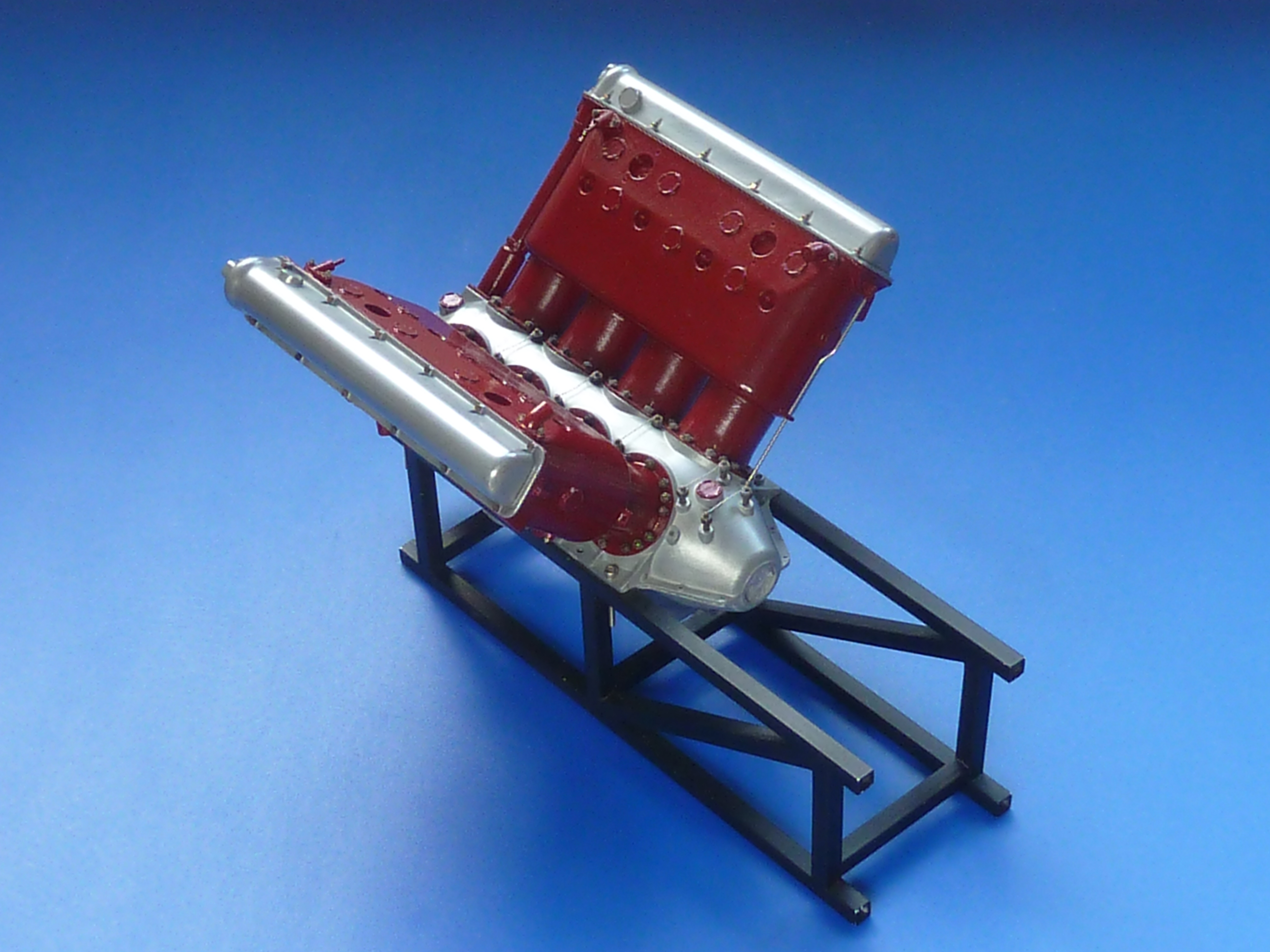
I’ve continued to push on with the two Hispano-Suiza engines, but the burgundy coloured one is going in a slightly different direction to the black.
After adding both cylinder banks to it was time to look at the induction manifold.
Previously it had been a single piece casting which worked quite well, especially in pewter. It was very awkward to remove the more delicate cold cast resin part from the mould though. The one installed on the black engine did suffer a little damage that had to be repaired. The arrangement also has no adjustment within it, so getting the cylinders exactly the same height and at 90° to each other becomes critical to a decent fit. I wanted something that was a little more tolerant of minor errors.
The obvious solution was to divide the casting up in to 5 parts, as it is on the real engine. You quickly appreciate that the original designers must’ve done this to allow for manufacturing tolerances, amongst other reasons.
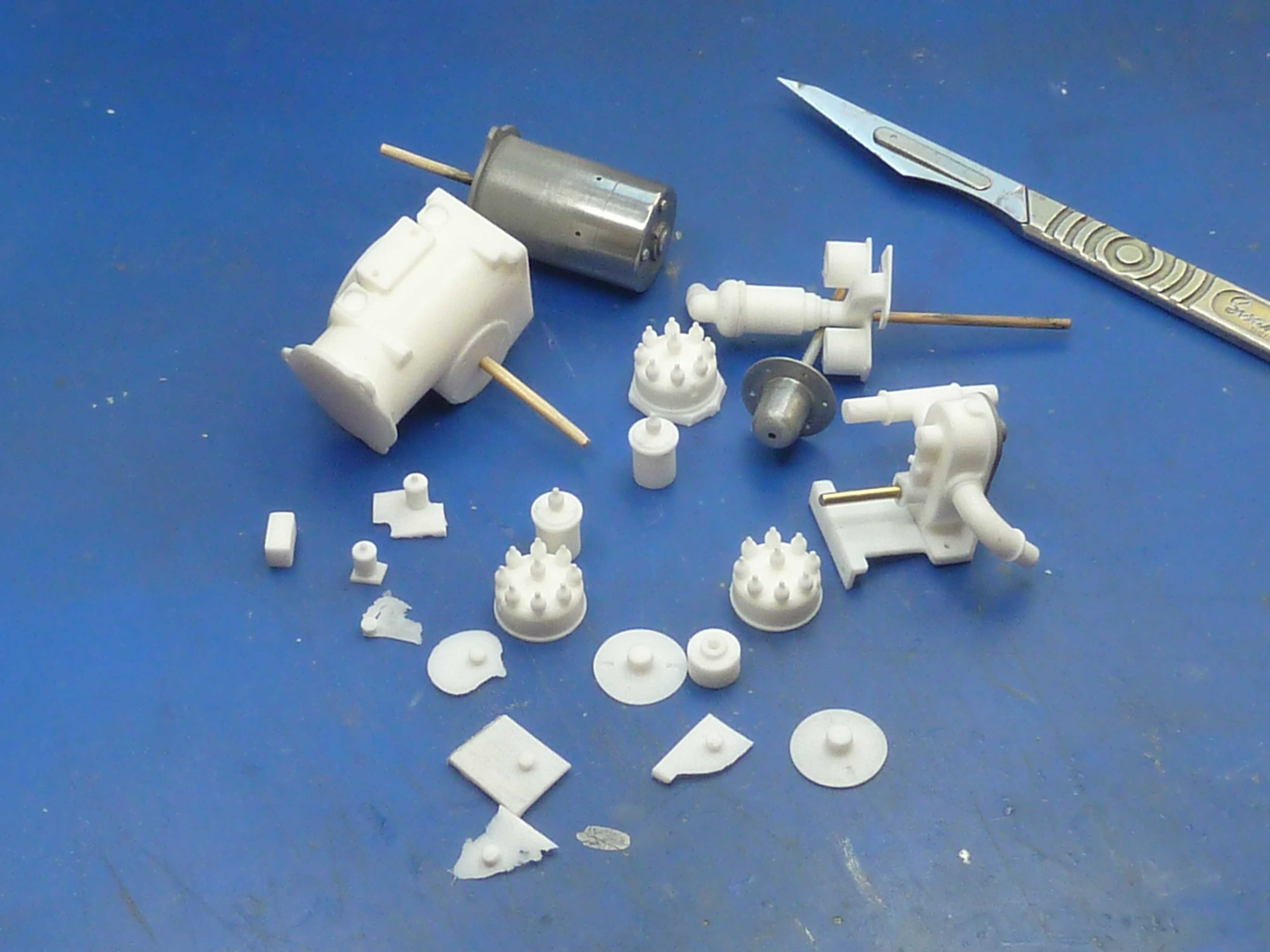
Hence a revised version was developed in CAD and sent off to be printed.
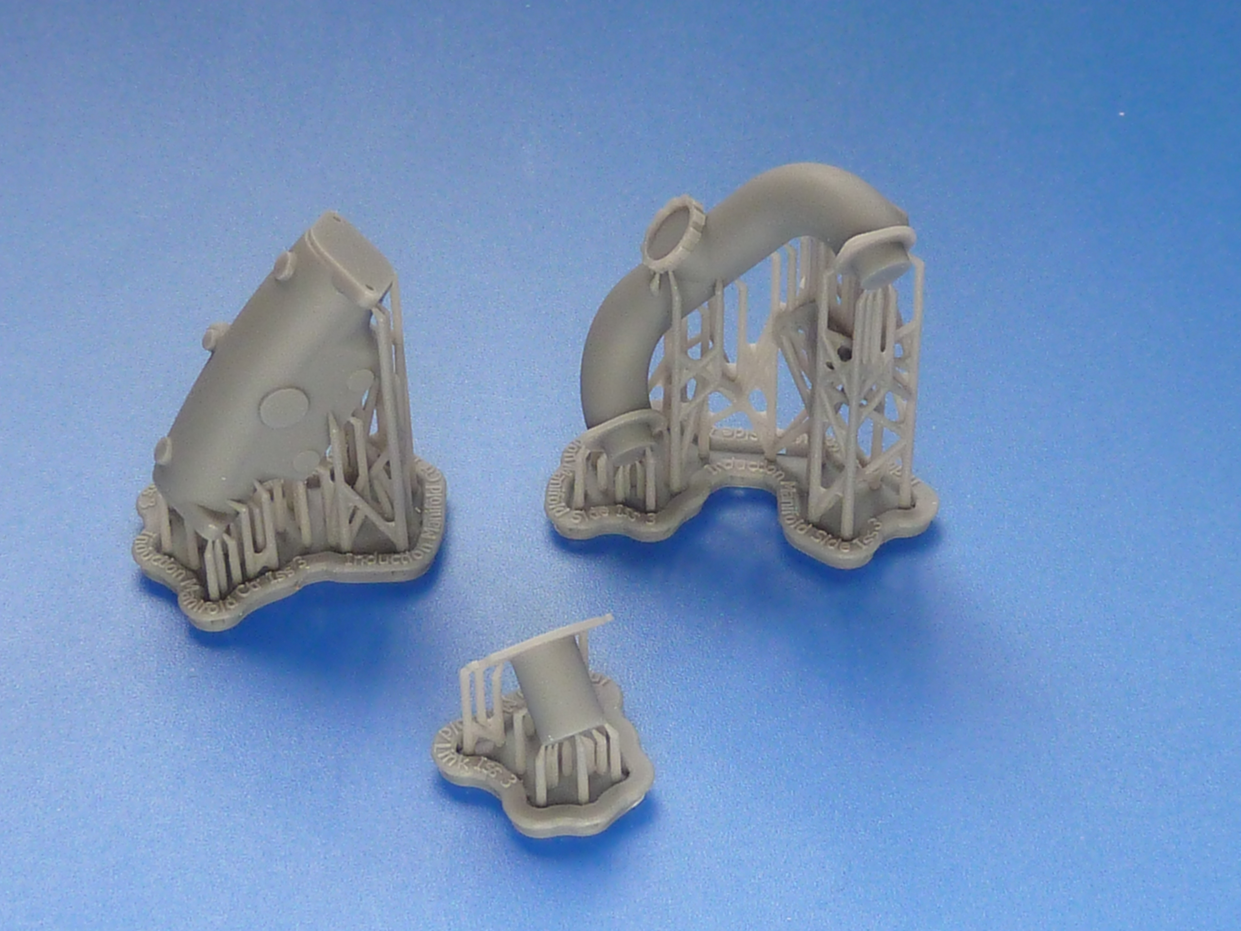

The link piece in the centre of the picture above is deliberately slightly over length so that it can be trimmed to a perfect fit on the engine, giving me the slight adjustment I wanted.
The link pieces were glued to the central casting and the outer parts dry assembled on the engine using 1 mm bolts to locate them accurately. Then commenced the trial-fettle-trial sequence making sure I reduced each link piece equally in length. During the process I also filed off the locating pegs on the bases of the side pieces because they were more trouble than they were worth to be honest.
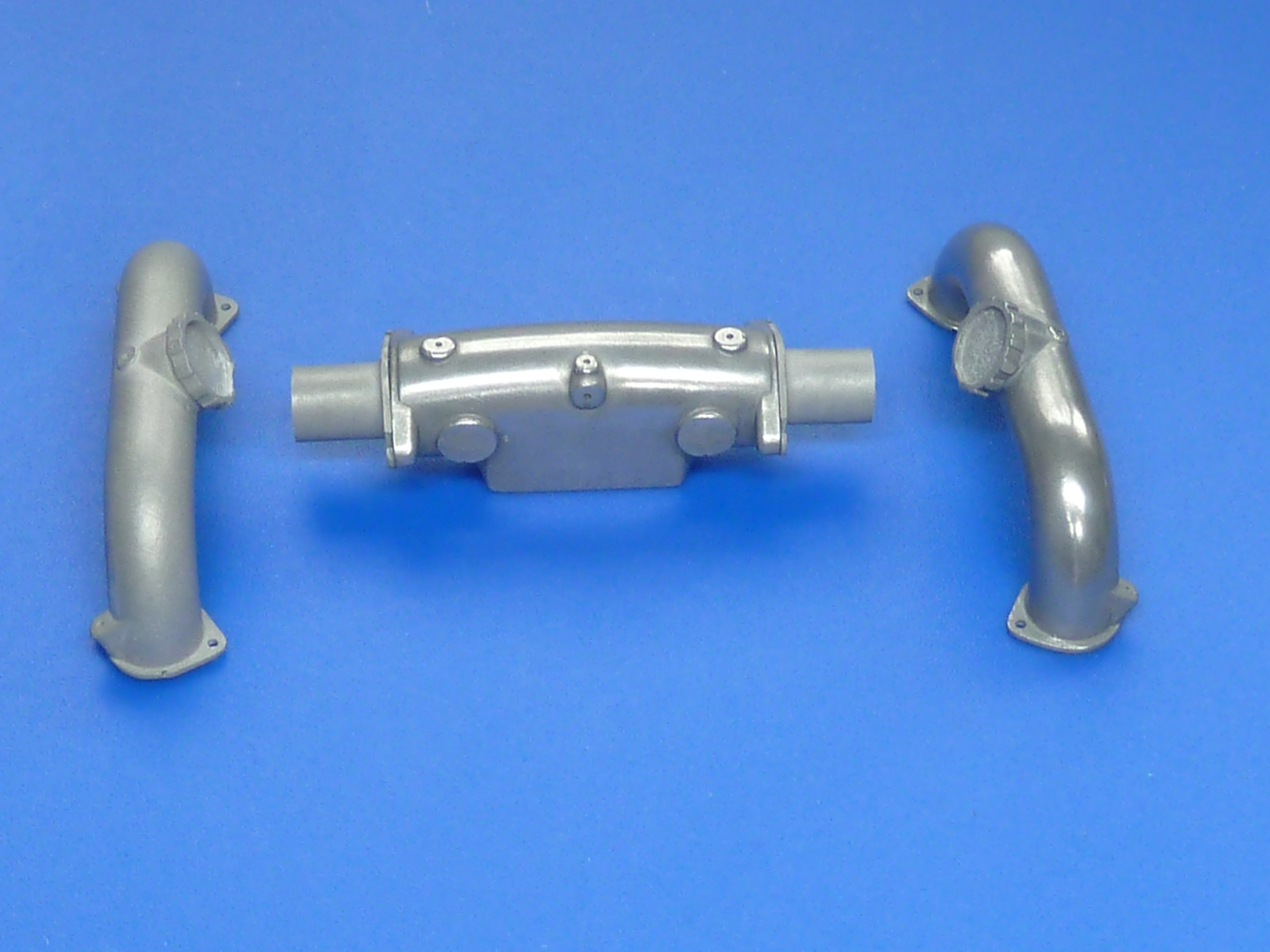
The result is shown below, and a it is definitely better fit than previously, though there’s no actual visual difference between the two arrangements.

The parts can’t be permanently fitted though until the carb has been attached as well as the plugs, ignition leads and their guide tubes in the V.
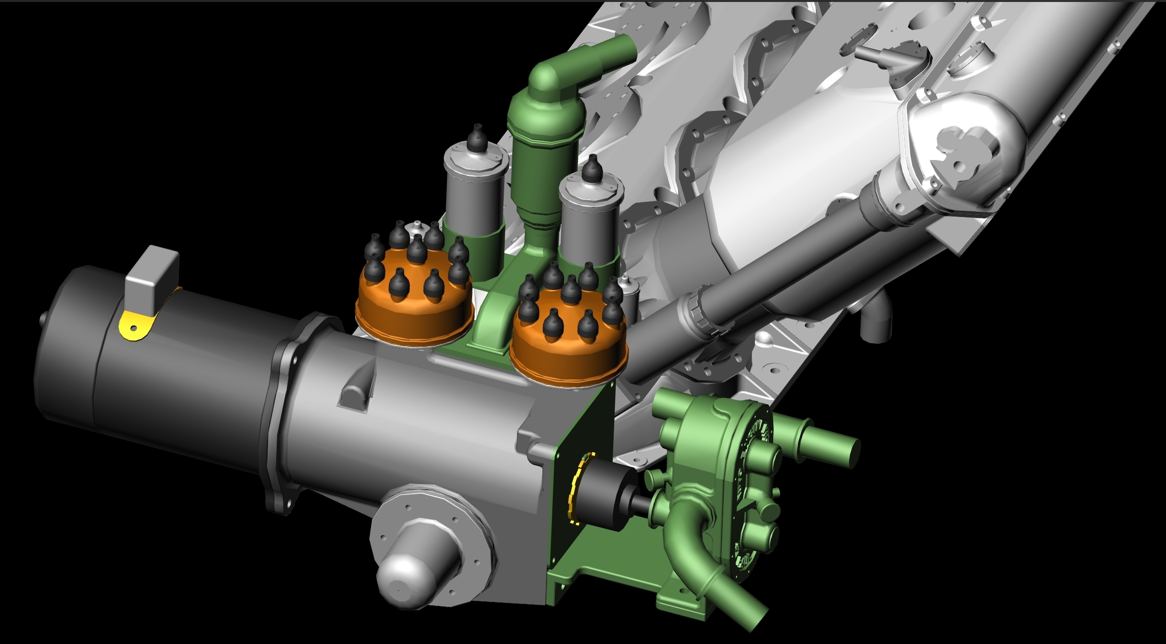
Speaking of ignition systems brings me on to the main change on this model. The black engine retains the magneto ignition system of the aircraft engine. The full Auto Engine Works marine conversion changed this to a coil/distributor version with dynamo. This makes more sense in a boat where swinging the prop is problematic to say the least, and a starter motor with charging system almost essential.
I wanted to model this arrangement on the burgundy engine, so it was back to CAD to develop…
Once again a set of .STL files were created and emailed to the 3D print bureau and 3 or 4 days later the printed parts arrived in the post.
STL = STereoLithographic which was the process used in the earliest 3D printers. The processes have changed, but the file type has stuck.


Moulds were taken and the parts cast in polyurethane resin. The dynamo and front face of the water pump were cold cast because they would have bare ‘metal’ areas I wanted to highlight. Incidentally, exactly the same resin was used throughout. The only difference is that the cold cast items have 67%, by weight, aluminium powder added. The end housing was also cold cast simply because I had a little mixture left over after the other two, and it seemed a shame to waste it.
The water pump faceplate came out quite well.

A quick bit of airbrushing later…

The black and silver components were sealed with a satin varnish.

The rest received a coat of burgundy gloss.

Once it had hardened I scraped back the faceplate of the water pump to highlight the company name.

The assembly also included a few photoetch components. The mask for them is shown on the right in the photo below. The large mask is for the exhaust system, including another drill template. I’ll come on to that saga in a future post.

The picture below shows it all assembled and mocked-up in-situ, but no plumbing or wiring has been installed yet. The pipe in the photo below is a trial fit, and I think it needs a smaller diameter one really. A bit inconvenient that, as the lugs are designed to take it. Guess which parts aren’t included in my CAD model…

The distributor assembly on the real engine includes a mechanical means of adjusting the timing advance. To replicate that it was back to CAD again. Then Photoshop to develop more etch masks. I cocked things up slightly on the latter. I forgot to add sprues to them and had to stop the etching process when it was 90% done and the components were still held together. Otherwise they would’ve fallen off the support and disappeared in to the bottom of the etch tank, never to be seen again.

After the residual flash had been removed the parts were stained and assembled using 0.7 mm brass pins as pivots.
I couldn’t resist mocking the whole thing up again on the rear of the model. It won’t be fitted permanently until I have sorted out the cooling pipe size issue and have installed the spark plugs etc. in the V of the engine, which will be the next job.

As an aside: I mentioned last month that I might put some mild weathering on one of the two engines, but wasn’t sure about the idea. To get an idea of how well it might work I carried out a trial on the scrap gearbox casting left over from when I dropped it.


I’m reasonably happy with the result, but need to include a bit more gloss black in the mix to give a more oily appearance. Other than that I think it’s on.
It’s been decided that the black engine will be the standalone desk curio and the burgundy one will go in the Miss Severn boat model. Based on that it’s the black one which will get the weathering treatment.

This 3D printing has really become big news. I assume the scale of things that can be printed is only defined by the quality of the material used and the strength it has or hasn’t, in keeping shape when being manipulated. For example, the internals of an engine that size could be made in theory, but in reality it would be too fiddly to actually use.
LikeLiked by 1 person
I’m operating at the limits of what the print bureau can provide in terms of detail, which is about 50 microns. There are newer machines available that can do better (25 microns), and a decent homeuser machine can do about 30 microns now, but you will be £1500 lighter for that privilege, so I’m saving my pennies.
https://all3dp.com/1/phrozen-shuffle-4k-review-3d-printer-specs/
Print size at that accuracy is limited. A home machine will typically give you a 160 x 70 x 120mm space to print in, which is fine for me. You can always print parts in sections too. If you’re prepared to fork out £10k you can enjoy print volumes of 33 x 20 x 30cm. I’ve no idea if there are bigger ones available, but I haven’t come across any yet. They’re not in my league though, so I haven’t looked very hard.
https://formlabs.com/uk/3d-printers/form-3l/
You can get much, much bigger prints, but the finished quality suffers. I haven’t really explored them at all as print quality is king to me. For industrial use it often doesn’t matter so much, and you can always drop the finished parts in a vibro polisher to achieve a nice smooth surface.
As for print materials the world is your oyster. All sorts of plastics which are extrudable are available. Resin cured by UV light are a bit more constrained, but you can still get a fair variety enabling you to print hard plastics, clear and soft rubber. The addition of dyes allow colour too. You can even print in wax allowing the generation of masters for lost wax casting.
Metals are available too, but they usually require some form of sintering post printing to turn them into a true metal component. The metal powder is embedded in the printing resin which is then burnt away during the sintering. The part does shrink in the process, but that is predictable and countered by printing slightly oversize to compensate.
The market is a rapidly changing one though, so all my comments will probably be out of date in a few months.
LikeLike
Hi
I found your blog page, almost by accident, and I have been totally enthralled by the Hispano-Suiza 8F. I am I going to explore some more later on, ‘cos it will be many long months before ever I shall be able to visit, so I shall browse in the meantime !
Stanley
LikeLiked by 1 person