
Having finished the engine diversion it was time to get back onto actually building the Miss Severn model. Not surprisingly these activities have focused around the engine bay and installing the new engine model in there.
In order to try out ideas and plan the installation of components, without the need to constantly handle the engine, I reverse engineered a CAD model of the boat’s hull and installed the virtual engine within it. That allowed me to quickly try different layouts of equipment.


One of the first activities was to manufacture an oil tank for the bay. I’ve no idea what size the Hispano engine requires, but I do know that the Hawker Hurricane with the Rolls-Royce Merlin had a 7 gallon tank. If it was good enough for Sydney Camm and Rolls-Royce, it’s good enough for me.
A quick box tank design was sketched out with the requisite scale volume (~2.2 fl oz since you ask) and some brass sheet cut and bent into to two C sections to form it. These were then soldered together, which was not the easiest thing as I’m no coppersmith.

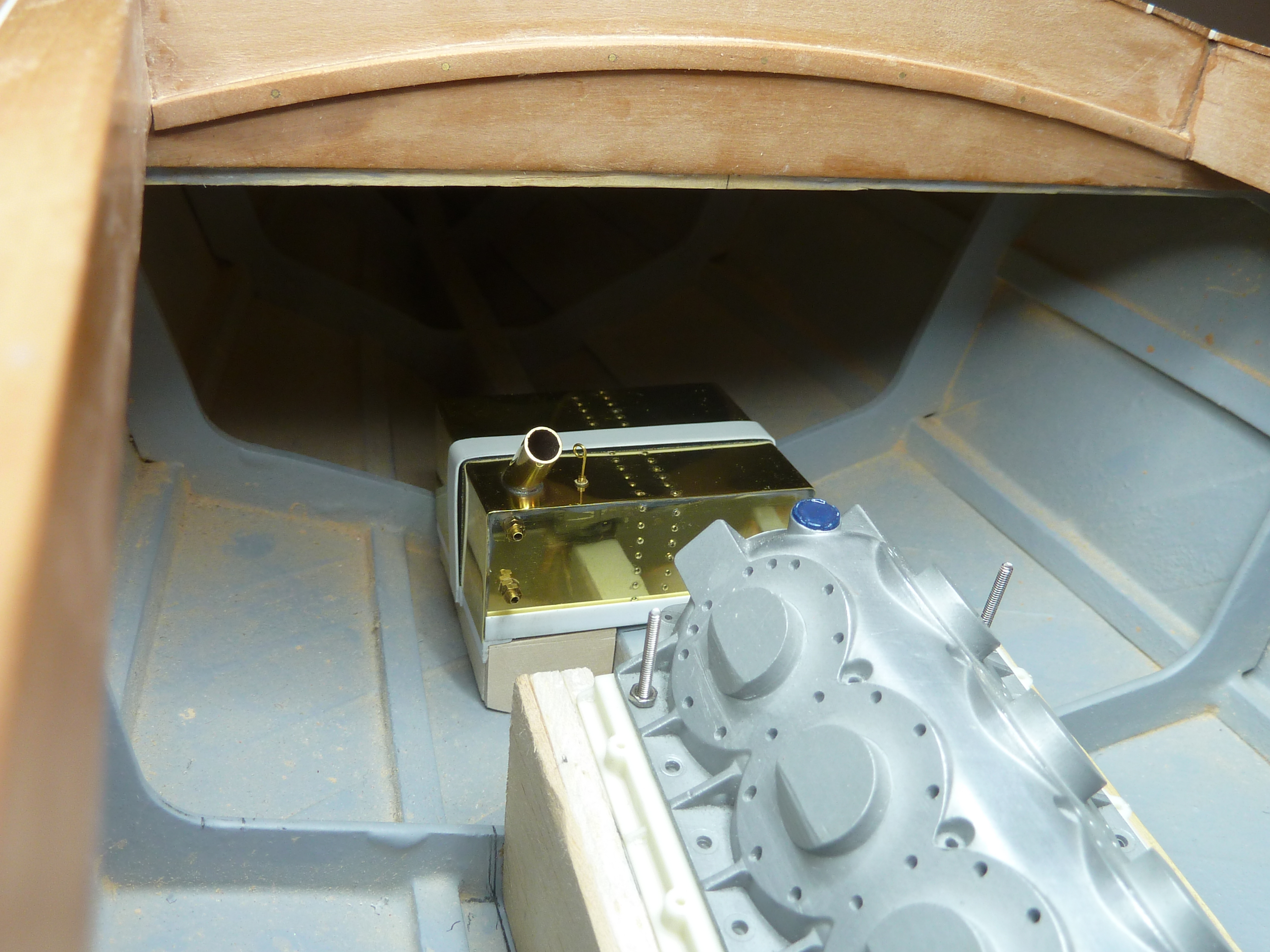
A small frame was made from plasticard to support the tank.

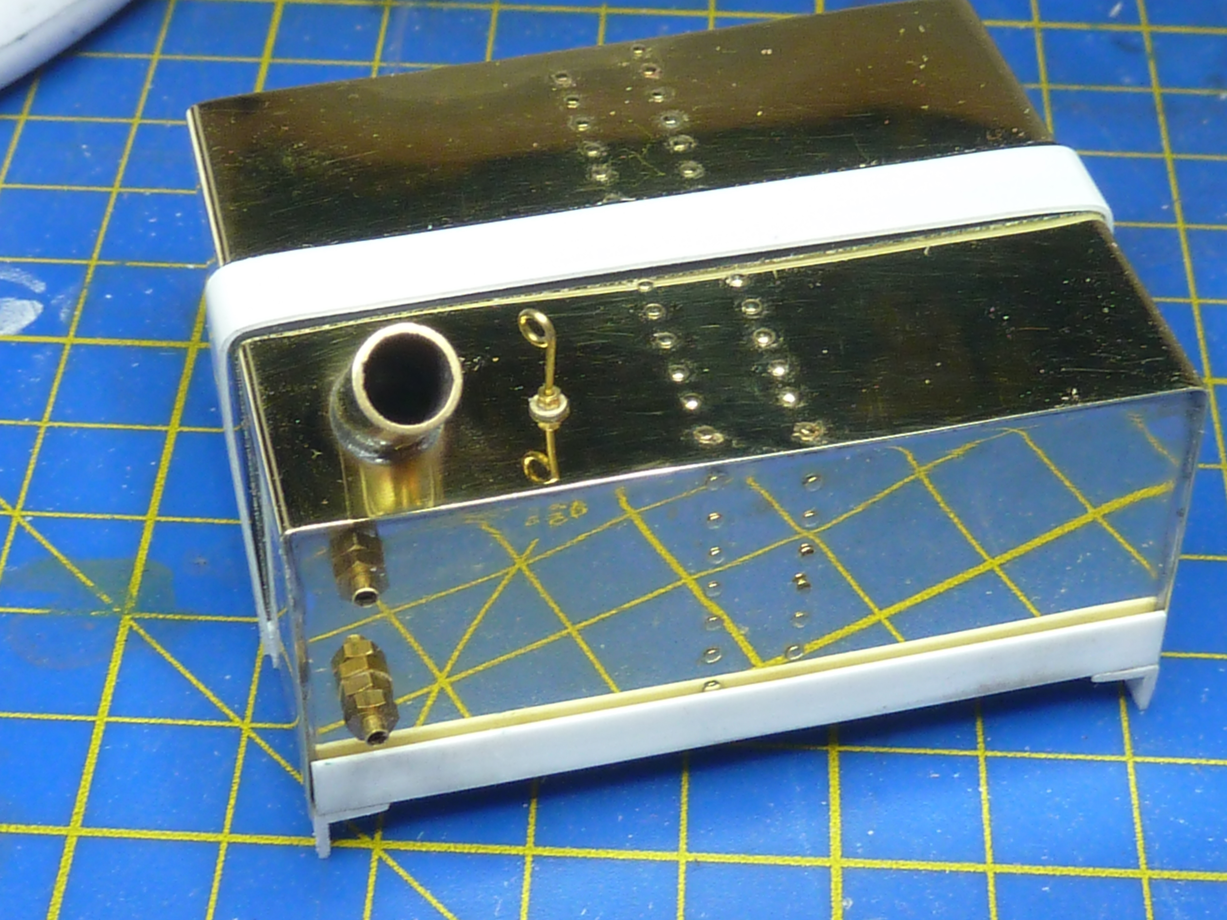
The filler cap was left off while I waited for some suitable sized brass tube to be delivered. Once that had arrived a simple cap was soldered up.
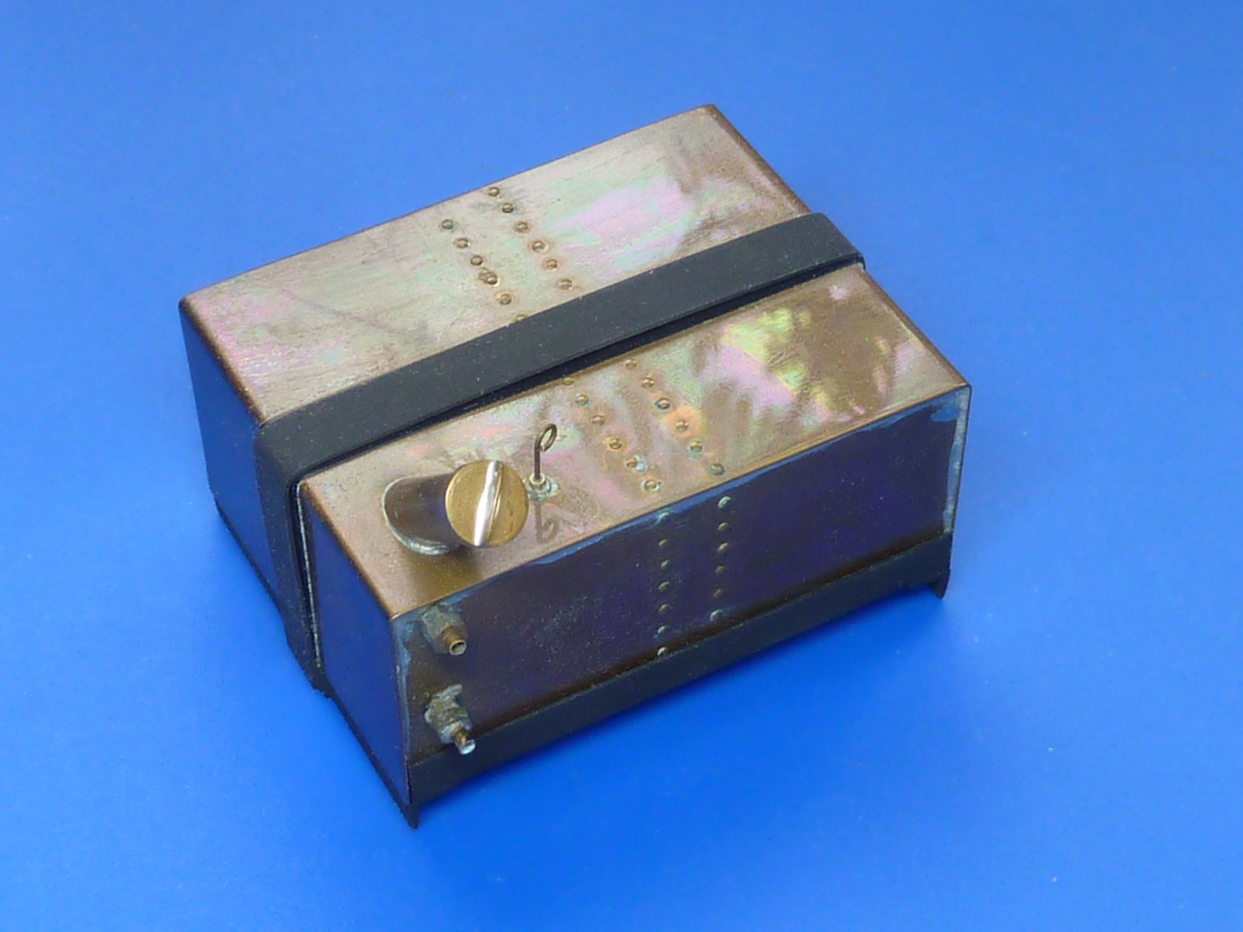
The whole affair was then ‘aged’ in another ammonia vapour bath. It was in there rather longer than I intended due to the distraction of our cat. Not a complete disaster though.
There’s not much room between it and the end of the engine. Fitting the oil pipes might be fun later.

That brings me on to the engine mount. Up to now I’ve been using a gash item made from balsa, because it’s easy to work. I wanted to turn that into something more substantial for the final model, so reached for the birch ply.
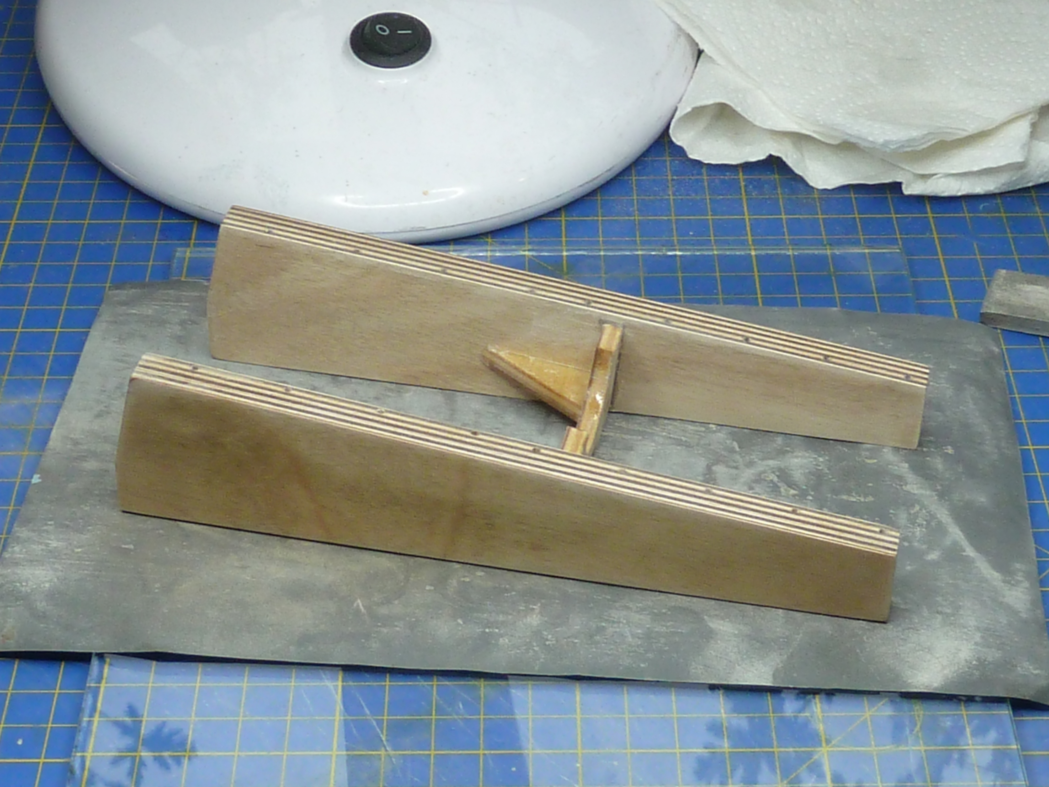
The inner parts of the mount will be completely hidden in the finished model so are more structural than scaled. It was quite an involved task to get the right shape, despite having built the balsa prototype. There was a lot of trial fitting and fettling before I got the shape I wanted. Particular attention was paid to getting the mount parallel to the main deck.

The whole affair was then given a quick coat of epoxy resin, and when that had cured, a sand smooth followed by a coat of matt light grey to match the rest of the bay.
The cockpit bulkhead in the engine bay was a bit of a mess as a result of hacking it about to make a hole for the gearbox to fit into. In order to restore order I’ve cut out some 1/64″ ply to act as a veneer and cover up the previous sins.

Having done that I wanted to make sure that it was actually possible to get the engine and gearbox combination into the bay while fitted to the engine mount. Trying to bolt the engine onto the mount once the latter is in the boat doesn’t bear thinking about.
The fit is exceptionally tight indeed, and requires more force than I’m strictly happy with to get it to snap into position, but it will go. Just. It amuses me to think that when I first set out designing the engine I was concerned it might look a bit lonely in the model’s engine bay.

As you can see from the picture above, having actually got the engine in place, I finished off the exhaust installation.
I’d always imagined that there would be a flexible section between the engine and hull mounted parts. When I was working as an aircraft designer I recall seeing a number of braided high temp pipes when vibration isolation and a degree of flexibility was required, so decided to try and replicate something similar. My design is based on some braided oil hose from a turbo installation left over from my kitcar building days.

While the hose might be flexible in real life it certainly didn’t want to go in the curves I wanted it to and was much too stiff for the model. The forces required to get it to lie ‘naturally’ were too much and something was going to break. In the end I resorted to putting in another supporting armature, made from 1/4″ copper brakepipe, to force it into the shape I wanted. The whole affair was then filled with epoxy resin, so it’s anything but flexible now.
As you can see from the above picture, I’ve also made some top-hat ferrules to support the pipe at the cockpit bulkhead end. They are made from brass pipe and sheet, soldered together, then bright nickel plated. They are designed so that the flexible section isn’t hyper-critical on length too. I’ll have a little leeway at both ends when it comes to final assembly.

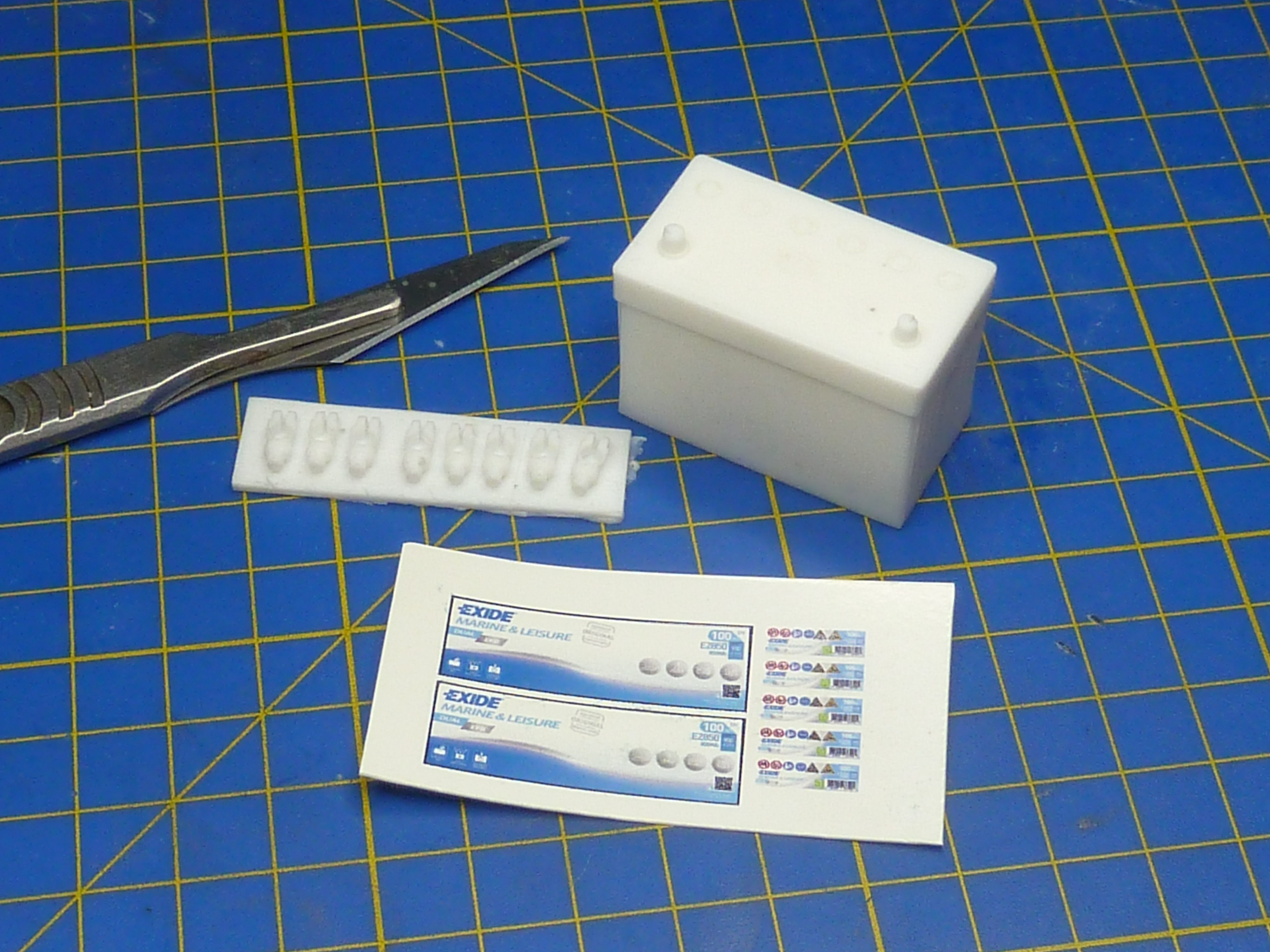
Next up was a battery.
I’m doing the model to look like a vintage machine might appear today. I’m already committed to that path actually, as the ignition wiring on the engine is modern style. No Gutta Percha insulation there.
Again I went down the 3D printing route because I’m much better at CAD than I am carving! A modern style battery was knocked up in CAD, printed, then used to make a mould for resin casting.

I also scoured the net for some pictures to make decals from. In this case an Exide marine battery of 100Ah capacity. I’ve gone for 12V too, as that is the norm for boats under 40′ apparently.
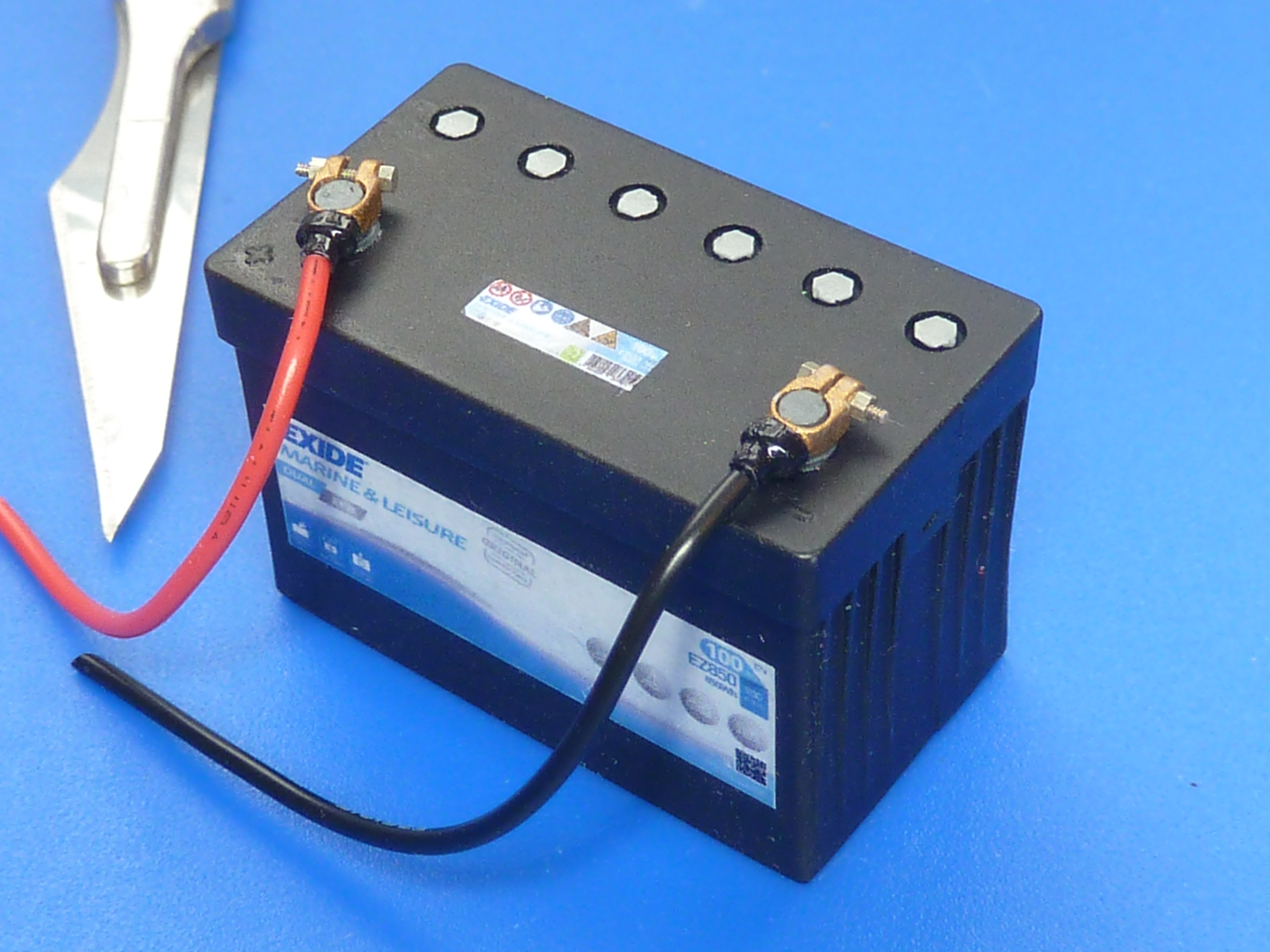
A quick coat of matt black followed by the decals and an overcoat of satin lacquer resulted in…
I had planned on a fairly detailed battery box for the engine bay, made from photoetched brass sheet, but some research revealed that most of them are simple wooden box affairs. Hence, that’s what I went for in the end.


I’ve also finalised the installation of the main cooling water feed. In the picture some trial duckboards are installed, but they won’t make it into the final model.

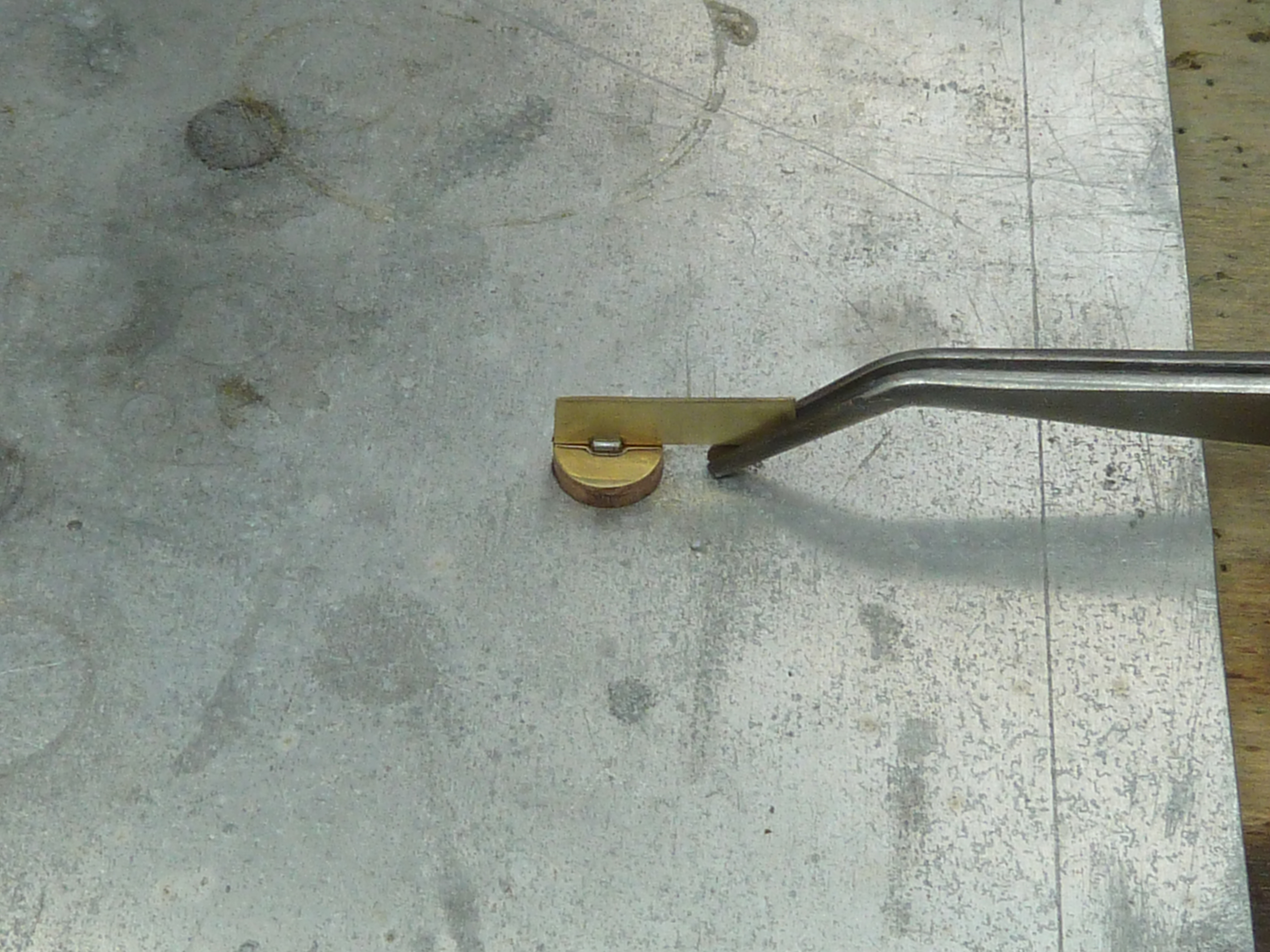
The latest activities have been centred around making the engine bay door hinges and frames. I decided to photoetch them (as I did on the Chris Craft model) because that avoids any distortion of the thin brass sheet.
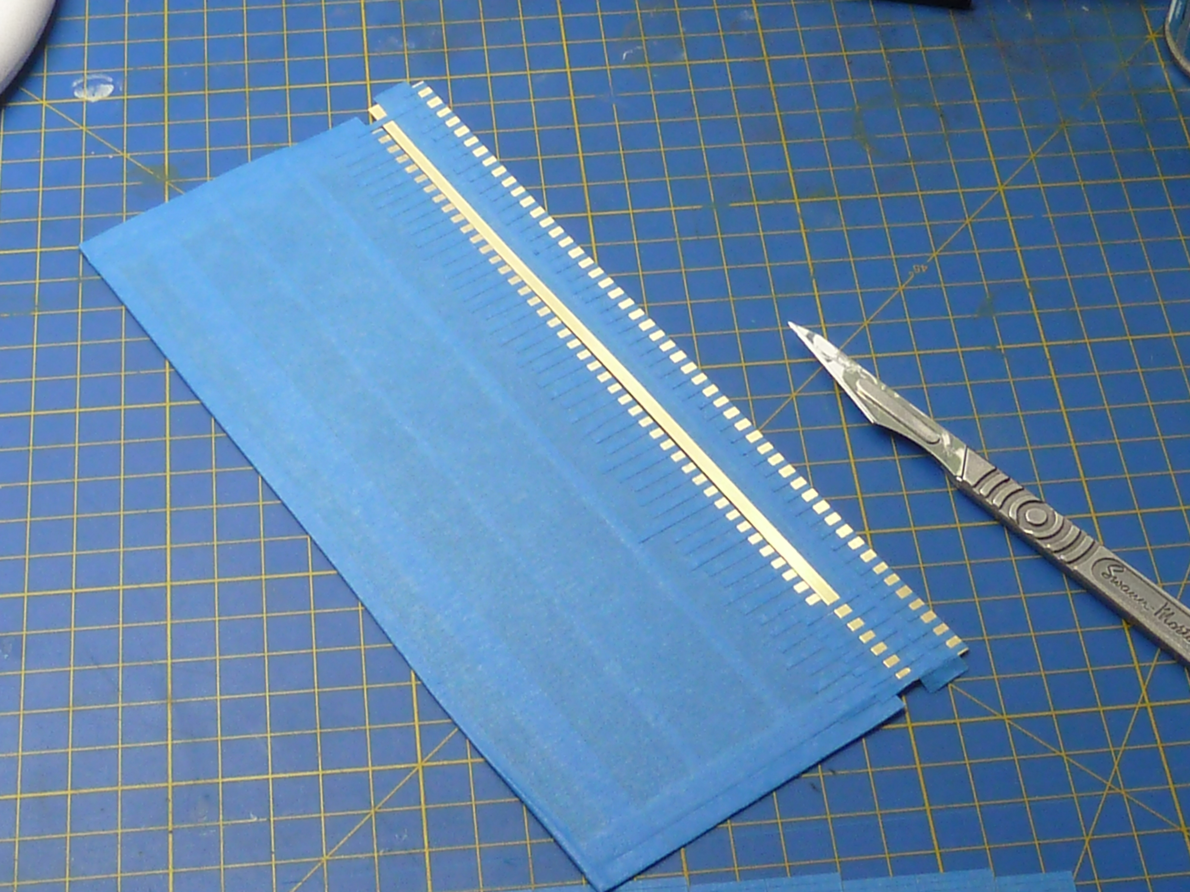

Things aren’t going so well at the moment though, as the first hinge is malformed! One side must’ve moved in the jig during the bending of the tabs, so there is a distinct taper to one wing. If I can’t get it apart I’ll have to start from scratch again which is a couple of days work down the pan.
Yours,
Not happy of Worcestershire.
Yeah, where the sauce comes from. Lessons on how to pronounce it are available at reasonable rates…
Alternatively just say Wuss-ter-sheer.
Next month, how to pronounce Leominster, Gloucester and Shrewsbury.

I continue to be impressed by the incredible detail you have managed to recreate in this model. It’s simply stunning. Could you perhaps hold a lesson on pronouncing ‘Loughborough’, that always confuses visitors to our wonderful country.
LikeLiked by 2 people
Loughborough! That’s advanced stuff.
LikeLiked by 1 person
I’m very impressed with the detail and skills on this build and am anxiously awaiting the next installment on your build as I work on finishing my Miss Severn build also. Learned a few things that really helped my project reading your pages.
LikeLiked by 1 person
I’m about 1/2 way through my Miss Severn build. Your engine detail leaves me speechless. I sit here looking your photos open mouthed and not breathing. 🤣
You don’t happen to 3d print them for shipping by any chance?
I’m still stunned.
LikeLiked by 1 person
Hi Mike I’ve sent you an email.
LikeLike