
I had hoped that this would be the last post on the building of these engines, but they will not lie down and give in. The exhausts in particular have been giving me grief.
Given how large they are, and the visual impact of that, I wanted them to have a real metal feel to them. I didn’t think I’d be able to achieve that with painting, and hence decided to build them out of copper and brass (see previous post). They’ve turned out to be some of the most complex soldered items I’ve ever made, but I got there in the end.
Below are the basic items for the burgundy engine which will be going in the Miss Severn type model. They are complete and copper plated, but do not have the inlet and outlet water cooling pipes fitted.

I’m aware that a lot of my pictures show things after they’ve been cleaned up, so here is a picture of one of the exhausts during assembly.

And after clean up, but before plating.

I wanted to plate them to give a homogenous copper look. I have seen welded copper exhausts on one restored boat from this era so, if designed correctly, they must be able to withstand the heat. I doubt brass ever would though, so my headers needed hiding under copper plate. For the doubters, remember they are bolted to an aluminium casting so if your heat management is right, they must be able to work. Aluminium melts about 400°C (750°F) before copper after all.
After plating with copper I wanted to give them an aged rather than a new polished look. I hit YouTube and tried a number of techniques found there.
I don’t know why, possibly because of the ‘brighteners’ in the copper plating solution, but Sodium Bicarbonate had zero impact. I even left the samples on a radiator overnight in a jar with bicarb solution in the bottom, but they were all still lovely and shiny the morning after. Acetic and citric acids were also tested (OK, vinegar and lemon juice to you) but didn’t really deliver. Immersion in an ammonia solution was exactly the opposite and just way too much. Verdigris all over the place in a very short time. Using burnishing solution worked quite nicely, but gave a blue/black patina, not the brown I was after.

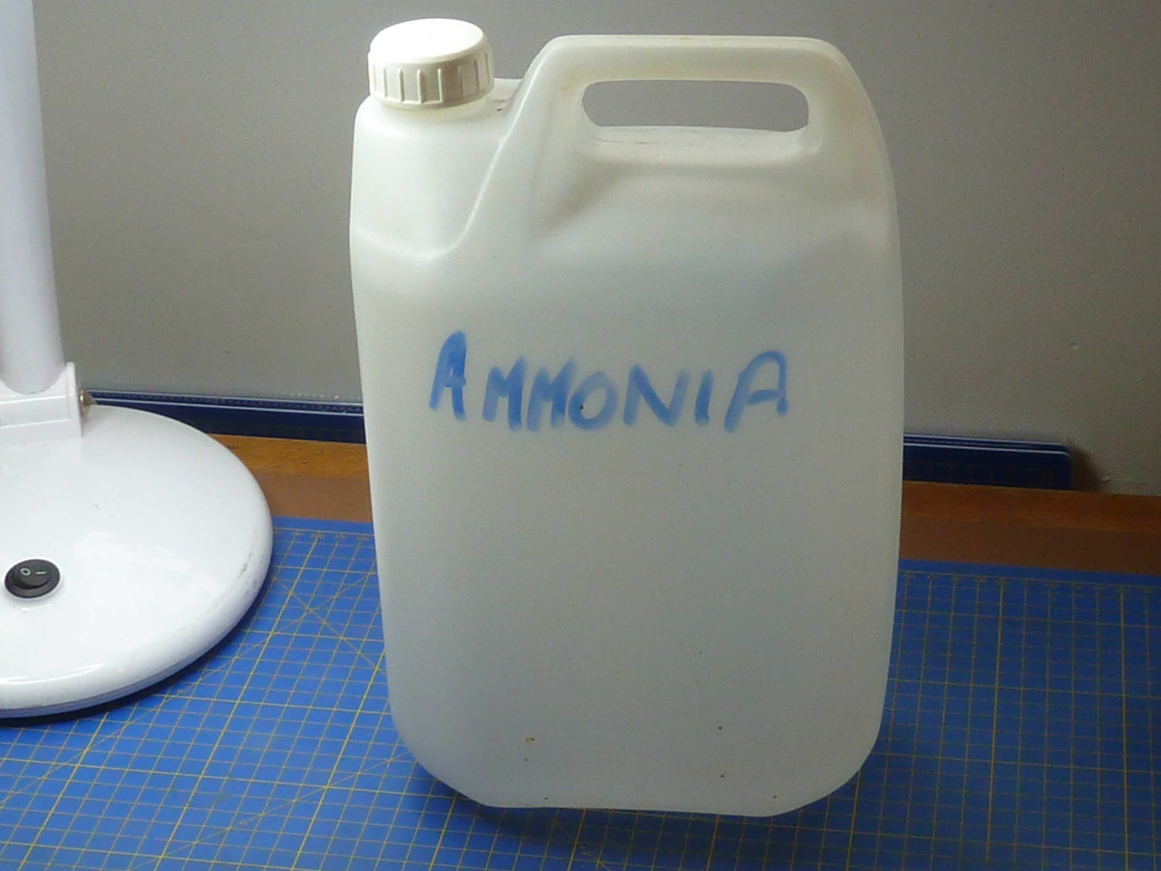
In the end I found hanging the copper items in an ammonia vapour bath was the best option. You need to make absolutely sure you don’t get any of the neat ammonia solution on the samples though, as that leads to verdigris spots.
That all sounds quite technical and posh, but the reality was a 5L plastic can with a cup full of ammonia solution (34% by vol) in the bottom. The parts were hung off the rim on wires with the top popped back on to limit evaporation. I left the parts in there for about 2 hours, but the temperature in my garage was about 5°C (41°F) at the time. I doubt they’d need that long in summer.
Having proved the method on some samples, I put the black engine’s exhausts in to treat them. It was a disaster… I’m not sure what happened, but the copper plate started to flake off all over when I removed them. Something must’ve contaminated the surface prior to plating, but I’ve no real idea what. Perhaps my acetone had something in it or the cleaning brush did.

Ho hum…
Whatever, I had an enjoyable afternoon removing all of the copper plate and cleaning up to start again from scratch. Thankfully that went without any further problems.
The burgundy engine has a slightly different and more complex cooling arrangement to the black one, primarily because of the alternative ‘distributor’ rear end arrangement. That required some pipes to feed the water jacket from the pump.
I tried making them from tube, but couldn’t get the tight radius bends I wanted without the tube collapsing. In the end I made them out of solid 4mm rod. Say nothing and no one will know!

Some before and after pictures of the soldering ops.

Risky stuff, as I only used one type of solder, so there was a very real risk of unsoldering old parts while I was adding the new ones.
(I mainly use a cook’s blowtorch for my soldering).
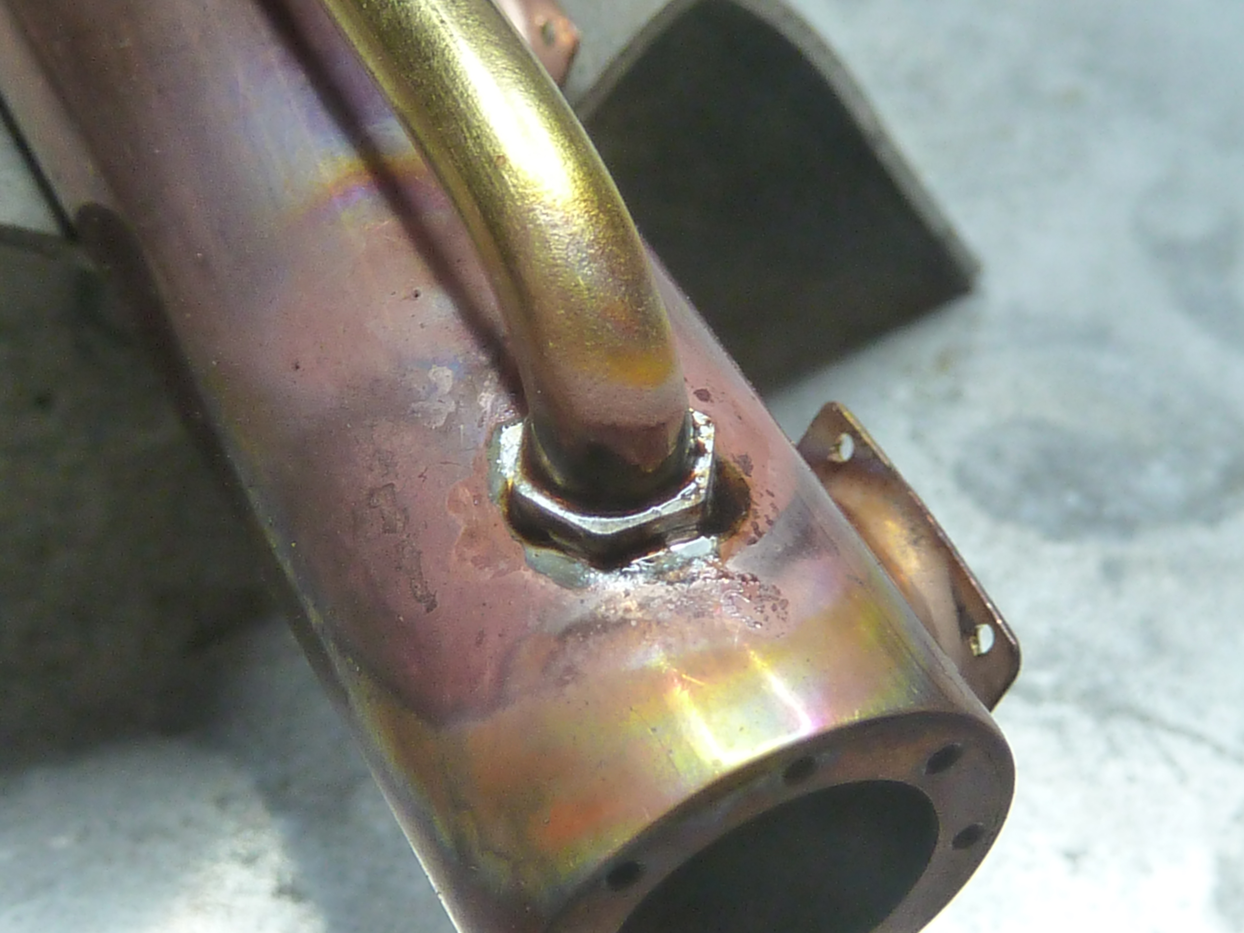
The end result after clean up and a couple of hours in the ammonia vapour bath. The steel spigots are there to mount the exhaust to the engine. The ‘mounting’ bolts will just be for show. The small water outlet at this end of the picture is actually a cold cast bronze part. I thought trying to solder a copper part on there was just pushing my luck too far.

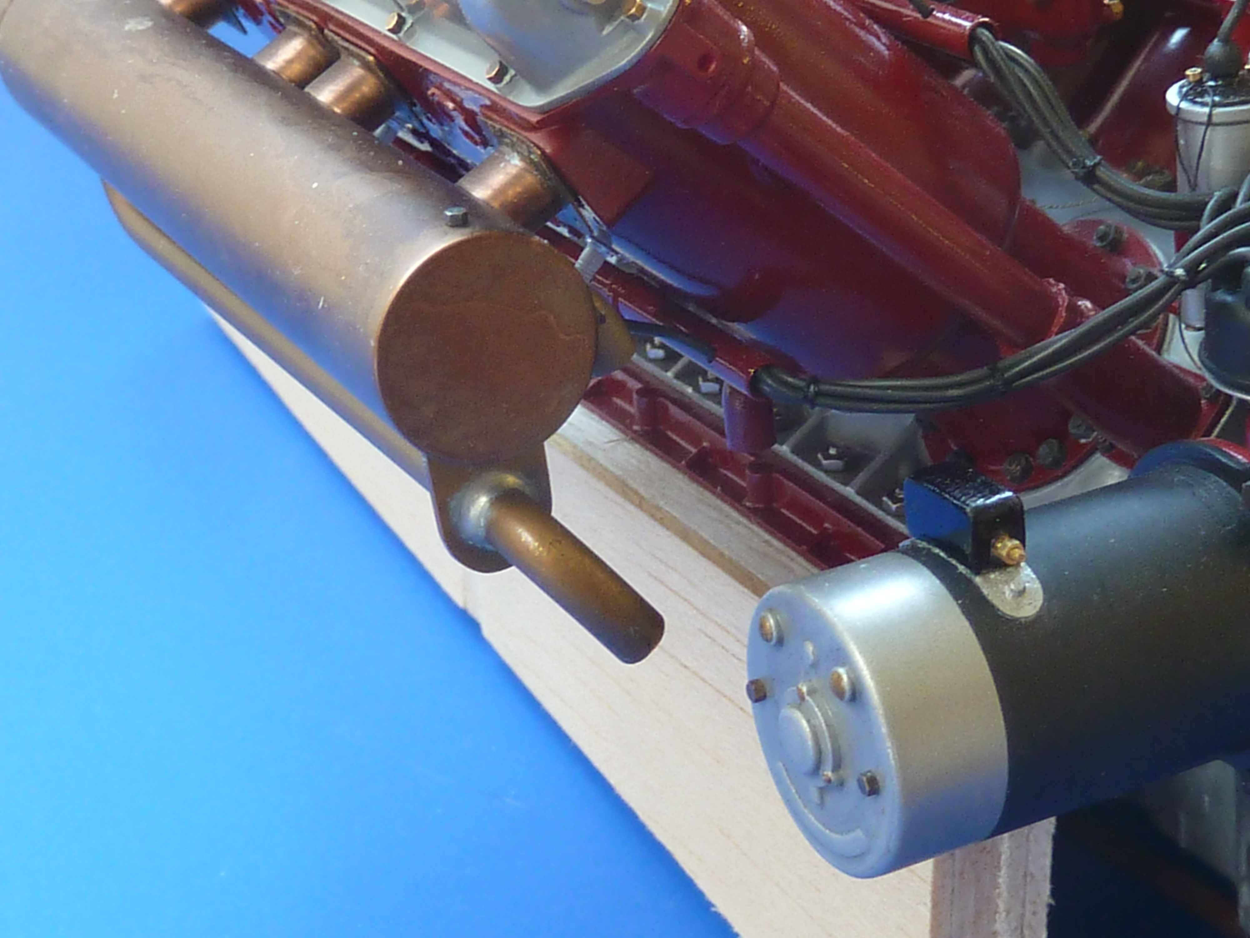
And finally fitted to the engine.

I just need to finish off the rubber hoses to complete the build. They will be similar to those on the black engine.


In addition to the exhausts I’ve also got around to finishing off the clutch. I call it that because I can’t think what else it would be, but I’m not actually certain of it. The thing has a massive mechanical advantage built in to it though, and it’s the only mechanism I can think of that would require that.
If you recall from my previous post I’d designed it in CAD and was intending to build it from photoetched parts.

The first version looked a bit weedy compared to the pics of the real thing, but did at least serve to prove the concept.

The parts were eventually made from etched 1.5mm brass sheet.
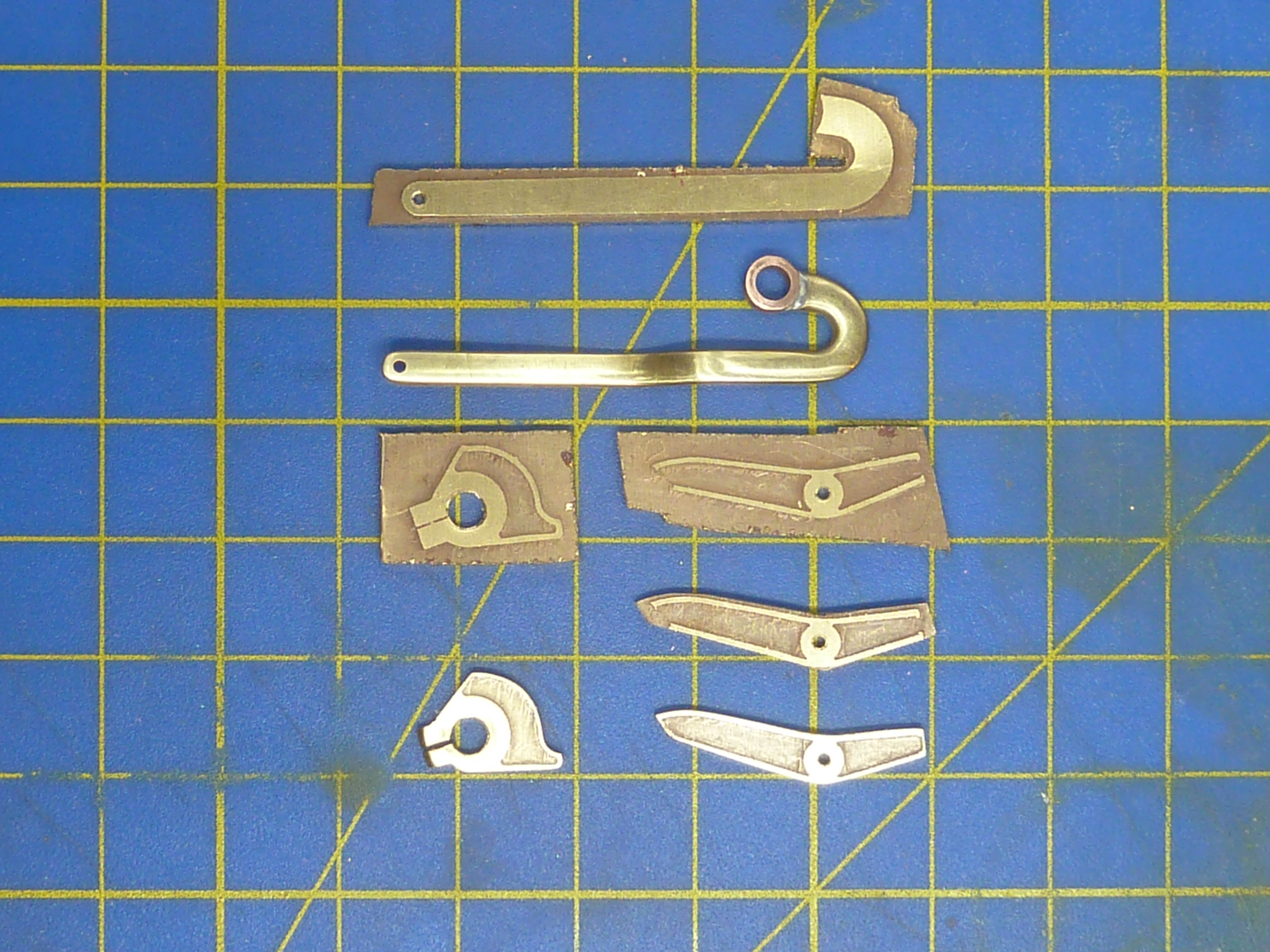
After burnishing they were installed on both engines. The thicker section looks much more in scale.
Another area that was finally completed was the carburettor controls on the burgundy engine. The black engine’s controls are much simpler as they don’t have to connect to anything and can be left as they were on an ‘as delivered’ engine.

However, as the burgundy one is going in the boat it does needs connections that can properly link to the cockpit controls. To that end I built a small brass confection out of sheet and tube to simulate some sort of Bowden cable arrangement.

I just need to run some thing black wires into the tubes once it’s installed in the boat.

I’ve finally got around to adding a maker’s nameplate to the burgundy engine too.

As the black engine will be a stand alone model in a little glass case I’ve made some name plates to go with it. They are the usual etched brass affairs, and are replicas of the plates actually fitted on the model. In fact the etch masks were made using the same print files scaled up.


Having installed the exhausts on the burgundy engine it was possible to start test fitting the thing in the Miss Severn model. I’d already checked the fit with my rough and ready 3D printed space model, but it was still a bit of a relief to find it went in without any problems.

I can now start to plan the layout of the engine bay. One of the main features of this will be the exhaust run to connect up with the kit’s in the cockpit. That requires some form of flexible coupling and I’m intending to use some braided oil pipe that I have to hand. A rough mock up of the what is planned is shown below and is based on some of the high temp piping that I have seen installed in aircraft.

Further updates on the engine bay fitting and equipping will appear a under the ‘Miss Severn’ series on this blog.
There will be one more engine one though, to complete the black engine’s build log.

Seeing all of your work in the blog posting is just incredible. Crazy great.
Thanks, Bruce Rudin 302 584-2412
>
LikeLiked by 1 person
Pete
That’s really great and so pleased you have finally managed to shake off the engines and get back to the boat as a whole. Just so good seeing the engine sitting in place. Is there much work to do to the engine bay before final assembly of the engine, and will you make it so that your client could take it out to play with if he wants too? A little toolbox hallmarked with “Pete’s Tools”….. 🙂
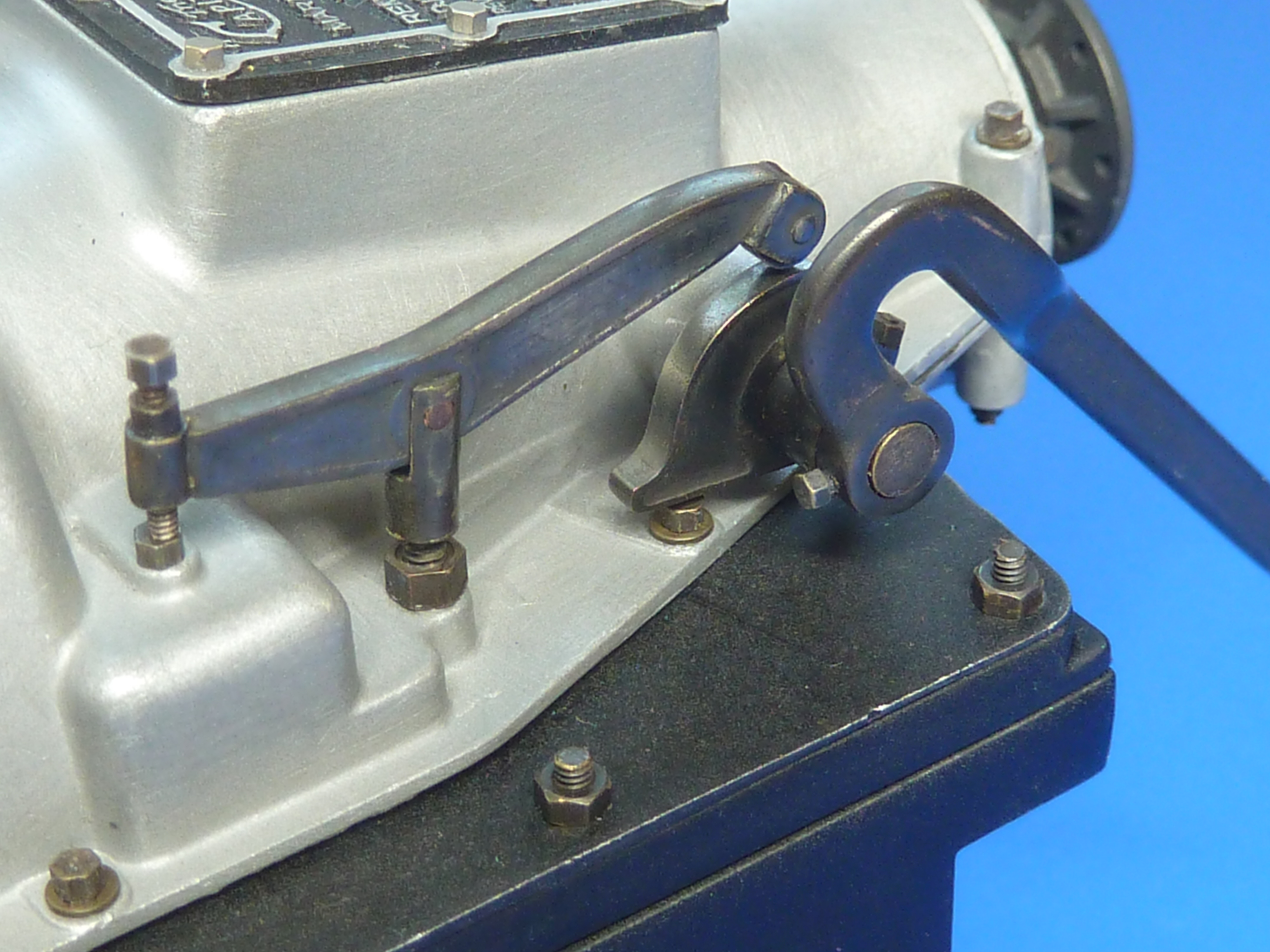
That clutch is interesting. The manufacturer made it very fragile the way it hinged there.
LikeLike
There isn’t that much to put in the engine bay really. The main things will be an oil tank and battery (need to find out if boats are 12 or 24V). Then there will be the connections of services and controls, and there aren’t many of them. Throttle, mixture, adv and ret, water, fuel and ignition. I suppose there should be fuel pressure relief valve and ignition solenoid too. A small toolbox is an interesting idea though.
The first thing to sort out will be the exhaust runs though. I’m 50% done on that.
LikeLike
That’s great. I am sure they are 24v DC, but that would need double-checking.
This guy, Howard makes some great tools (though most are onesided etches) and brilliant toolboxes in 1:24 scale, but it might give you some ideas. I bought his toolboxes and tools for a diorama before I ever thought of trying photo etching for myself. – worth a looksie.
https://www.kitformservices.com/photoetch.html
Obviously means making up some drawings and etching away again, but that’s second nature to you now.
LikeLiked by 1 person
Apparently the large majority of boats under 40ft use 12V electrics. Only beyond that does voltage drop start to become a problem and 24V start being used.
Also as a 1930s boat 12V is more likely I suspect. So a 12V battery it is.
LikeLike
I suppose also, as plane and boat engines were car engines and interchangeable at that time, as in the Hispano, that would also make a lot of sense.
LikeLike