I am based in a quiet corner of the UK and worked for 20+ years in the aerospace industry in the research and development fields, both as a design engineer and project manager. However, a decade ago I reluctantly had to take medical retirement and my glittering career came to a shuddering halt.
As a result of the retirement I suddenly found myself with more spare time than I was used to, combined with a limited physical ability to fill it. One of the things that now fills that time is model making. The activity isn't new to me though; I've been making models on and off since I was about 8 years old with varying degrees of fidelity, though hopefully the general trend is up. However, I now have the time and inclination to indulge myself fully.
This site was set-up as a means of making pictures of my models and build threads available to friends who were interested in them rather than boring everyone to death on Facebook and elsewhere. If anyone else enjoys them then all the better.
Well it has been rather a long time since I was able to put an update on here, but hopefully they’ll be a bit more frequent in the future.
I’ve not been entirely dormant during the hiatus, but have done precious little physical modelling and rather a lot of CAD modelling. That has built up quite a backlog of CAD projects that need to be turned into physical models. They should appear in due course, health providing.
Miss Severn has languish on my lounge floor during the break from modelling and has been a frequent reminder of what I’ve been missing. However, I’m back now and Miss Severn has been receiving some much needed attention.
The hull has finally been given its first coat of varnish. Finding a crystal clear varnish that is compatible with the Tamiya acrylic rattle can paint has been a tale in itself. I’ve tested numerous products, most of which caused the paint on the test samples to pucker up and wrinkle. I did try using traditional yacht varnish, but the tint in that made the aquamarine hull colour go a peculiar shade of green. Water based resins were OK, but didn’t really give me the finish that solvent based ones can. No pictures of the hull unfortunately as I didn’t want to disturb it while the varnish is hardening. Dust is a perennial problem here.
The other small bit of progress has been in bright nickel plating the rub rails for Miss Severn, and the Chris Craft 19′ Runabout. Miss Severn’s longest rails are about 40″ long which was much too large for my small facilities here. I did investigate sending them off to get them done professionally, but the quotes for that were also much too large.
In the end I opted to make a special plating tank out of 6mm PVC foam board and bought the necessary pure nickel anodes and titanium wire to connect them to the power supply. The whole affair looks a little Heath Robinson but does work surprisingly well. I was concerned about having a fairly unwieldy chemical bath knocking about in my garage but clamping it to the workbench makes it much more stable and an end tap allows 95% of the chemicals to drained off in situ. The bath only needs to be unclamped to recover the last few dregs.
Plating Bath – Not super hi-tech, but works well.
The rails were polished up, cleaned with acetone, then given a copper strike coating. This isn’t strictly necessary with brass, but I wanted to make sure the bright nickel had a good base to adhere to. After the copper strike, the parts were given a quick rinse and then plated with bright nickel.
I’m happy with the result and it’s saved quite a few pennies.
I’m still not doing so well on the health front but have been able to make some progress on the Miss Severn model. It’s been a bit two steps forward and one back though.
I have at least finally got around to finishing off the deck fittings.
The cutwater needed several goes at plating to get a satisfactory finish, but we got there in the end.
I’ve also plated the chocks. Only the fairleads remain.
As all of the trial fitting of components in the engine bay is pretty well done I decided to refresh the paint for the final finish. Unfortunately there was a problem…
I thought I’d finished the rear bulkhead of the bay with epoxy resin so was a bit cavalier in my paint choice because epoxy doesn’t care too much. however, I’d forgotten that I’d actually used polyurethane varnish and this reacts badly to cellulose paint.
I was really quite vexed at this point. You know, REALLY vexed and quite upset.
So there then commenced a fun session of sanding down and removing all of the offending mess. After several sessions, of sanding and recoating I finally got back to where I should’ve been all along.
It’s still not as sharp as I’d hoped though.
The next step was priming the hull. No matter how closely you inspect the finish the grey primer always seems to reveal a smattering of defects and blemishes that you’ve somehow managed to miss. So there was a general sanding and filling of pinholes.
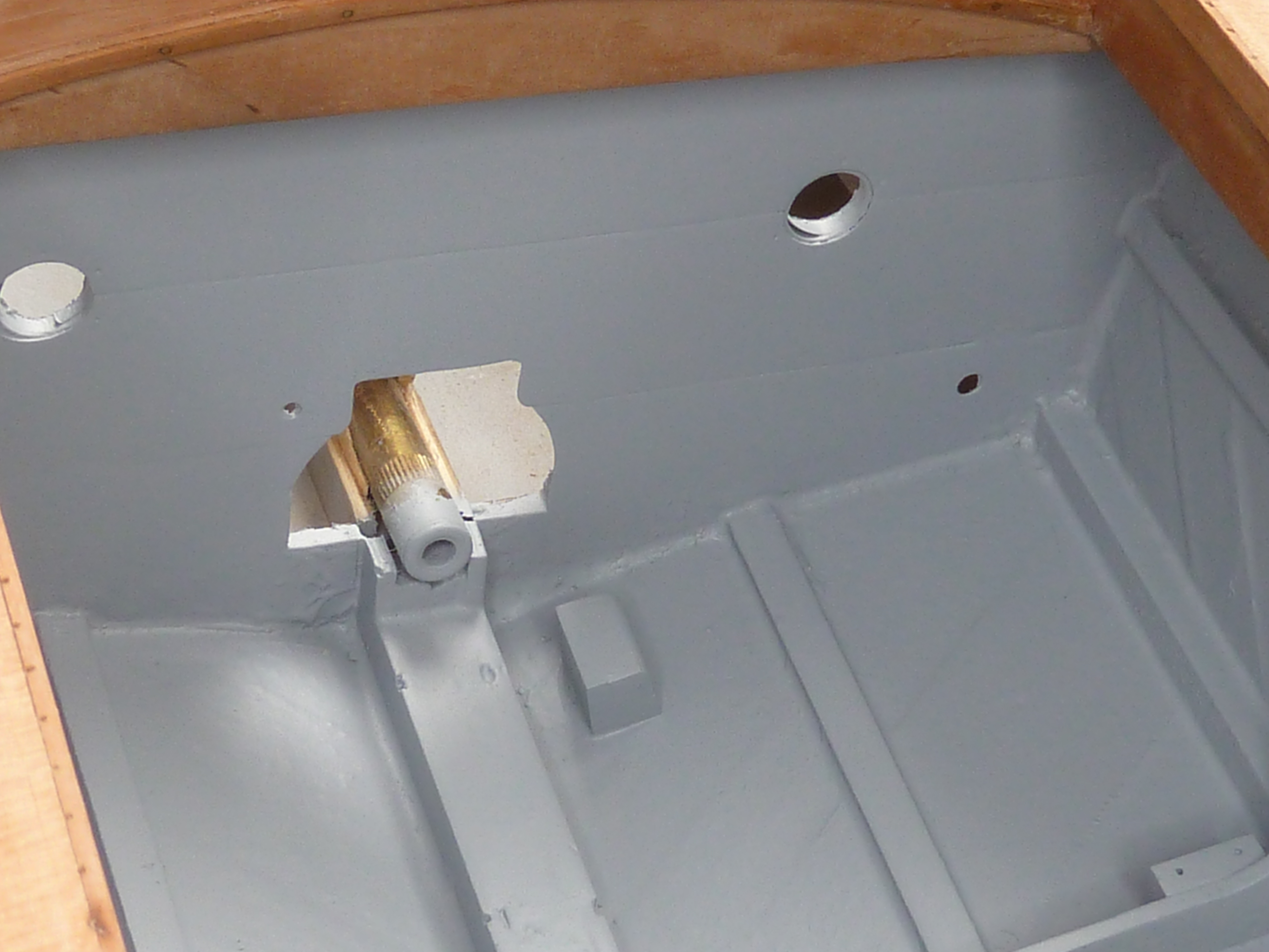
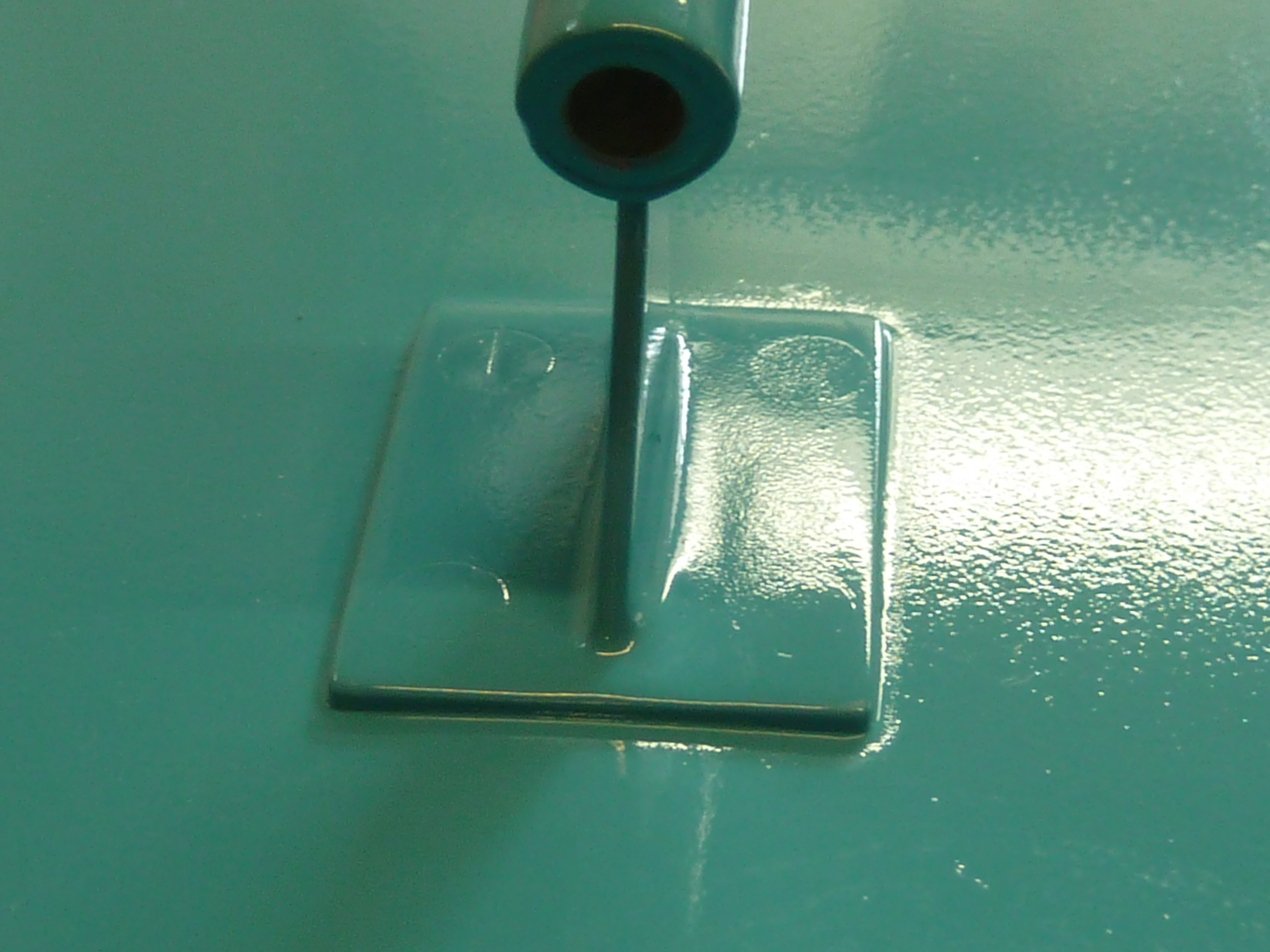
I had intended that the strut for the propshaft would be polished brass, but when I offered it up to the boat it looked too toy like, Hence I decided to paint it the hull colour after all. Also, somewhere along the line of resin coats and sanding, the small flat island I carved out for the strut’s base had been lost and needed restoring.
The masking tape is there to mark the outline of the strut and also to protect the surrounding paint while I filed away.The rod in the bearing is there purely as a paint mask.
The strut comes ready drilled in the kit which wasn’t ideal for me. I did enquire whether it was possible to get an undrilled one but that is how Mack Models receive them. I didn’t want 4 totally out of scale rounded headed screws showing, so counter sunk the holes and used countersunk screws to hide them. Once they were sanded flat the gaps were filled with body putty and that sanded level. The strut is also glued in place using epoxy resin. Just enough to squeeze out the edges and fill any remaining gaps. I fitted the strut before I removed the masking tape in the previous pictures which made cleaning up the excess epoxy very simple. Pull off the tape before the glue is set and you’re left with a nice clean edge that self smooths.
Despite all the prep, the screws are still slightly visible when you get the light at the right angle. I’ve had this before and remain convinced that the filler shrinks very slightly over the days after the instructions tell you it is fully ‘cured’. Hopefully I can remedy that later.
The orange peel finish is due to the use of rattle cans for the paint, but will disappear once the varnish coats are applied.
Having sorted the primer coat and the strut, I finally got around to throwing some paint at the hull. The first attempt went badly. I painted the waterline then masked it off to paint the aquamarine colour. Despite making a test piece, which went fine, the blue reacted with the white paint yet again. To say I was annoyed would be an understatement. I like to think I have some idea of what I’m doing when building models now, but to make a beginners error, twice in quick succession, rather questions that. What was especially annoying was that I made the test piece specifically because I was concerned about the problem as I was mixing paint from different manufacturers and that went perfectly.
There are no pictures of the mess as I was too annoyed to take them. In fact I walked away from the whole thing for a few days to calm down.
A less than enjoyable day was spent sanding all of the mess off, cleaning up and re-priming before a second attempt at painting , with paints all from the same manufacturer (Tamiya), which went OK.
I was using rattle cans for the main areas as the area is a little large for my airbrushes, and modelling desk. They didn’t give me a very sharp water line, so I re-masked that, decanted some of the white paint out of the can and applied it with my airbrush which gave a much sharper result.
Next up will be the staining of the woodwork. The transom is already done. However, I think I will apply a coat of varnish to the hull bottom and sides before I start mucking about with the decks. It’ll protect the paint a little, as it is still quite soft.
In parallel with all of the above I’ve been investigating methods for producing decent gold lettering for the boat name and registration numbers. I’d like them to be a convincing gold, and real gold if at all possible.
I mentioned briefly in an earlier post that I’d been messing about with gold leaf and even done some trials.
The Miss Severn lettering on the cutting mat was a trial of gold leaf application. It’s a mess because I also tested to see how easy it is to remove. (Ans: It isn’t. You get one shot.)
The results of the trials were OK, but not fabulous by any means. However, I did learn that:
I need a lot more practise to become any good at gold leaf application.
Gold leaf is more pervasive than glitter.
I’m not stellar at hand cutting letter masks.
Based on the above, especially the glitter bit, I’ve decided not to let gold leaf anywhere near the lovely black hull this time around. As a result I’ve been investigating other options. In particular I’ve been lusting after a vinyl cutting machine to allow me to produce decent complex paint masks for several years now, and have finally taken the plunge and bought myself a Silhouette Cameo 4 which is thoroughly living up to expectations.
It has already enabled me to cut some decent masks from thin vinyl.
The scalpel is there just for scale. It had nothing to do with the cutting.
Small islands in the text still need a lot of care such as those in the ‘A’s of Annapolis and they are about the limit of what the Cameo 4 will do I think.
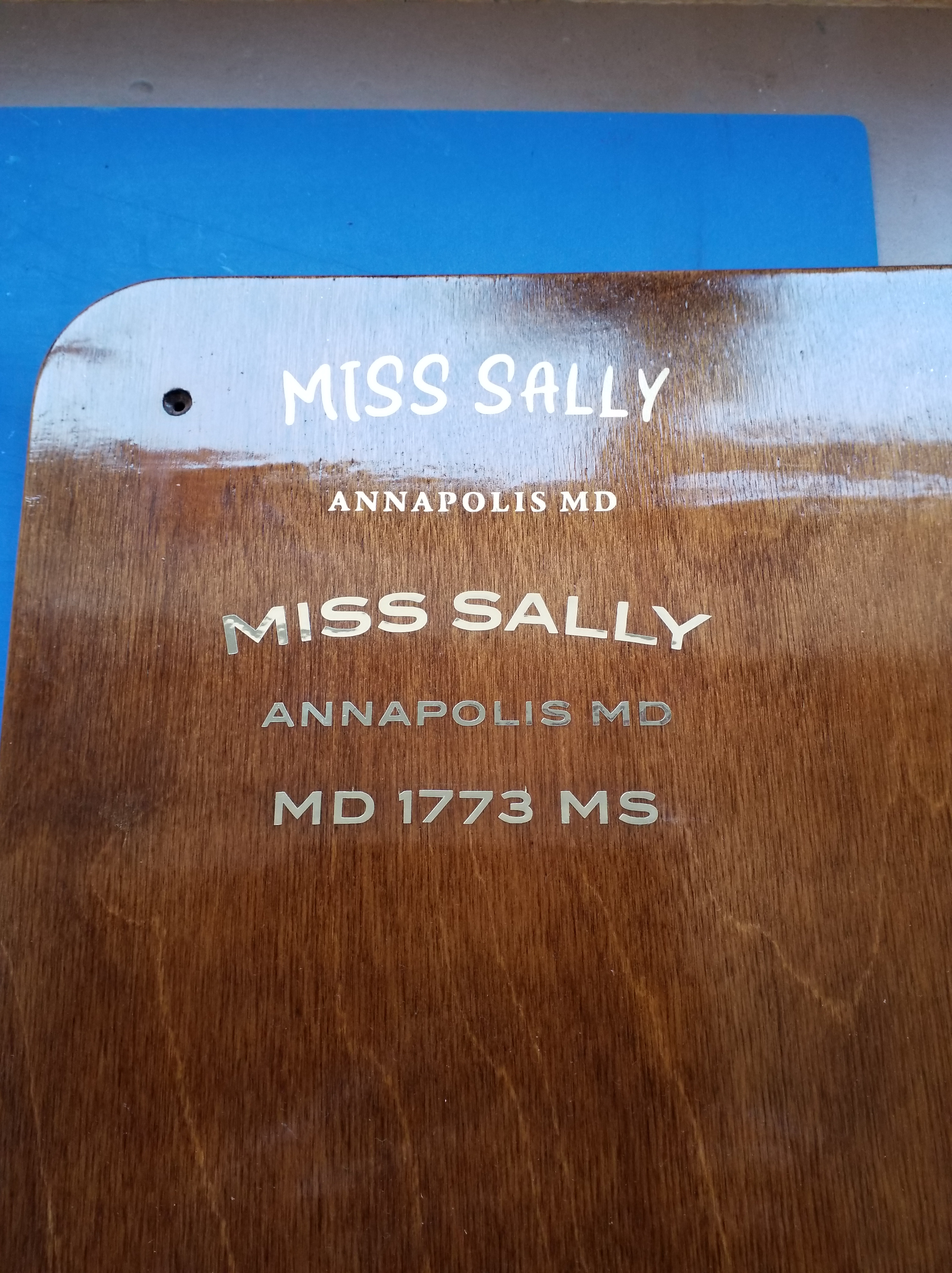
By the way, Miss Sally is what the boat is going to be called now, not Miss Severn. The model is quite a way from a replica of Miss Severn at this stage anyway, and it personalises it too.
I’ve also experimented with using the machine to cut gold vinyl.
The top lettering has been airbrushed with gold paint using the mask in the previous picture. The lower lettering is cut from self adhesive gold vinyl foil.
The vinyl foil I used was billed as being 23 microns thick, but my micrometer tells me it is 85 microns including the adhesive. That’s a bit thick to hide under varnish easily. It would take a lot of coats to hide the edges. Hence I’m still trying to locate some real gold self-adhesive foil, like the material they use for shop window lettering. That is billed as being 2-3 microns thick, and having looked closely at the lettering on shop winds in the past I can believe it. I can get small amounts of it from the US, and vast amounts locally for silly money. I haven’t as yet found someone in the UK that will sell me a meter or so of the stuff to play with. The search goes on…
I mentioned in my last post on the Miss Severn build that I had been filling the time between sanding sessions developing some CAD projects for possible later builds. Here are a few CAD renderings of the models just to give you and idea of what’s been going on at MBIQ Mansions.
Hispano-Suiza 8Ab 180hp direct drive.
This is one of the early versions of this engine. 11.8L and 180hp. It looks very similar to the Wright-Martin H3 engine that I have already featured on this blog, but is actually quite a bit smaller. The Wright-Martin was a licence build of the H-S 8F and was enlarged to 18L and 300hp.
The next is an Hispano-Suiza 8Be which developed 220hp and was one of the last developments of the 11.8L version of this engine. It achieved the extra power by increased compression and higher RPM. In order to keep propeller speeds down the unit was fitted with 0.75:1 reduction gearbox. This was a bit of an achilles heel of these engines as the gearbox was prone to failure and there were several instances of the gearbox and propeller leaving the aircraft before the pilot had finished using them.
Post war the engine featured in a number of racing boats following another marine conversion by Auto Engine Works of St. Paul, Minn. The conversion included updating the magnetos with coil ignition and replacing the reduction gearbox with a bespoke unit featuring a reverse gear. I am developing a converted model as time on the Miss Severn build allows.
Hispano-Suiza 8Be. 220hp with reduction drive.
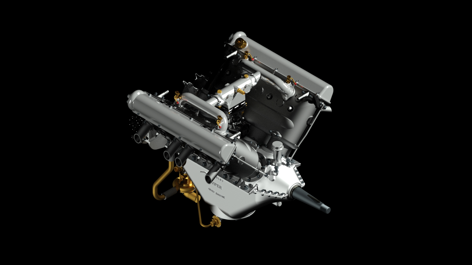
Wolseley Viper 4.A*. 200hp Direct Drive
The next model is a Wolseley Viper 4A*. This engine developed 200hp and was directly driven, thus avoiding the problems of the later H-S 8. The design was a licence build of the Hispano-Suiza 8 engine, but many improvements were introduced during the process and the engine is different from the original version in quite a few areas if you start looking closely.
Wolseley Viper 4A*. A licence build of the Hispano-Suiza 8. 200hp direct drive.
Le Rhone 9C, 80hp Rotary
The final model I’ve been working on is the Rhone 9C engine. Sometimes known as the 80hp Rhone to distinguish it from the later 9J which developed 110hp. The engine was fitted to a number of aircraft, including the Sopwith Pup which is where my interest comes in. I have a long term aim to build a 1:8 Sopwith Pup to go with my Hasegawa Camel model and this will be a key part of it. The work on the main engine is complete, but I haven’t drawn any of the ancillaries yet.*
* Update: The CAD model of the engine is now complete, as you may have deduced from the opening image on this post.
Le Rhone 9C. 80hp.
So, those are some of the background projects bubbling along. All have been designed to be built at 1:8 scale as that is my preferred format. When or whether they will ever appear on here as builds is anyone’s guess!
It’s been a while since my last post, but progress has been a bit slow and there hasn’t been that much to report.
I’m at the hull varnishing and sanding stage, and the noise of sanding is a problem for me. After a few hours of sanding I have to take a couple of days off doing quiet things to recover as the main feature of my illness is a hyper sensitivity to even modest noise levels. Notwithstanding that I have been progressing steadily, and the enforced breaks have allowed me to progress a few other projects in CAD. These will probably appear on here in the future.
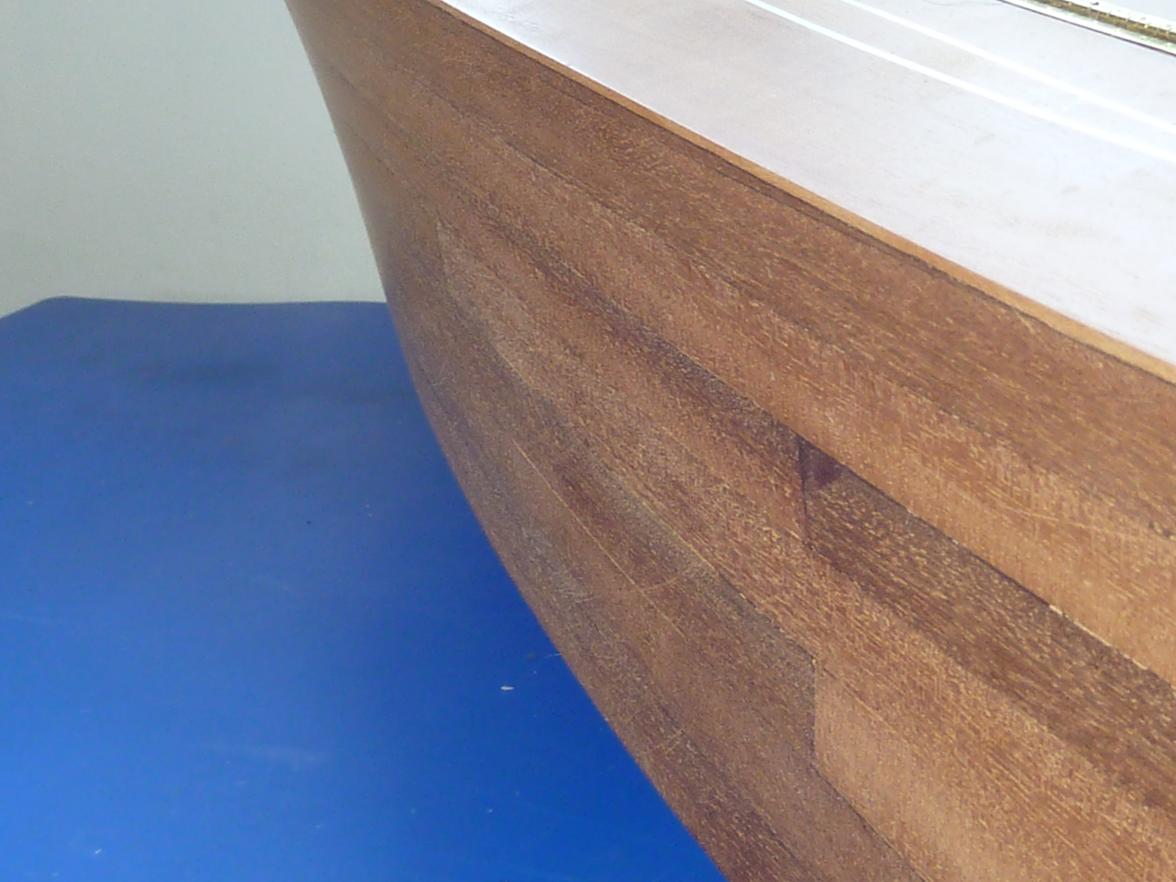
In my last post I left the hull at the bare sanded stage ready for varnishing.
As this boat is going to have gloss black sides with an aquamarine bottom the finish on the sides just has to be smooth. For that reason I’ve chosen to epoxy resin coat it using EasyComposites’ XCR Resin. It’s pretty easy to use and you can recoat in about 40 mins. In fact if you leave it even a few minutes longer than that the subsequent coat suffers badly from “fisheyes” and is very uneven. The short time between coats means that it is easy to build up the thickness for subsequent flatting back. There is an element of self levelling in the resin which leaves a good finish.
Next the dreaded sanding which was undertaken with 120 grit wet/dry paper and finished with 400 grit. It needs to be done wet to avoid clogging of the sandpaper, after a few sessions and breaks I was left with:
It wasn’t all plain sailing though. A few planks sprung loose on the forward starboard side, due to the CA glue not spreading completely under them I suspect, as it was quite a tight curve and the mahogany could’ve done with pre-bending really. When I came to sand the area flat I had to break into virgin wood again to achieve that, which necessitated more coats of resin and sanding..
We got there in the end though.
I had intended to move onto painting, staining and varnishing at this point, but having thought it through I decided to make and trial fit the hull brightwork. Any scuffs and errors could be hidden under the initial coats of paint. It was as well that I did because it suddenly occurred to me that I had completely forgotten the fender rails at the stern. The kit doesn’t have them. It just has the chrome car trim stuck to the side of the hull. Hence, they don’t appear in the instructions.
Cutting the long triangular taper wasn’t the easiest bit of woodwork I’ve ever done as the front section is wafer thin. It stretches about half the length of the actual trim.
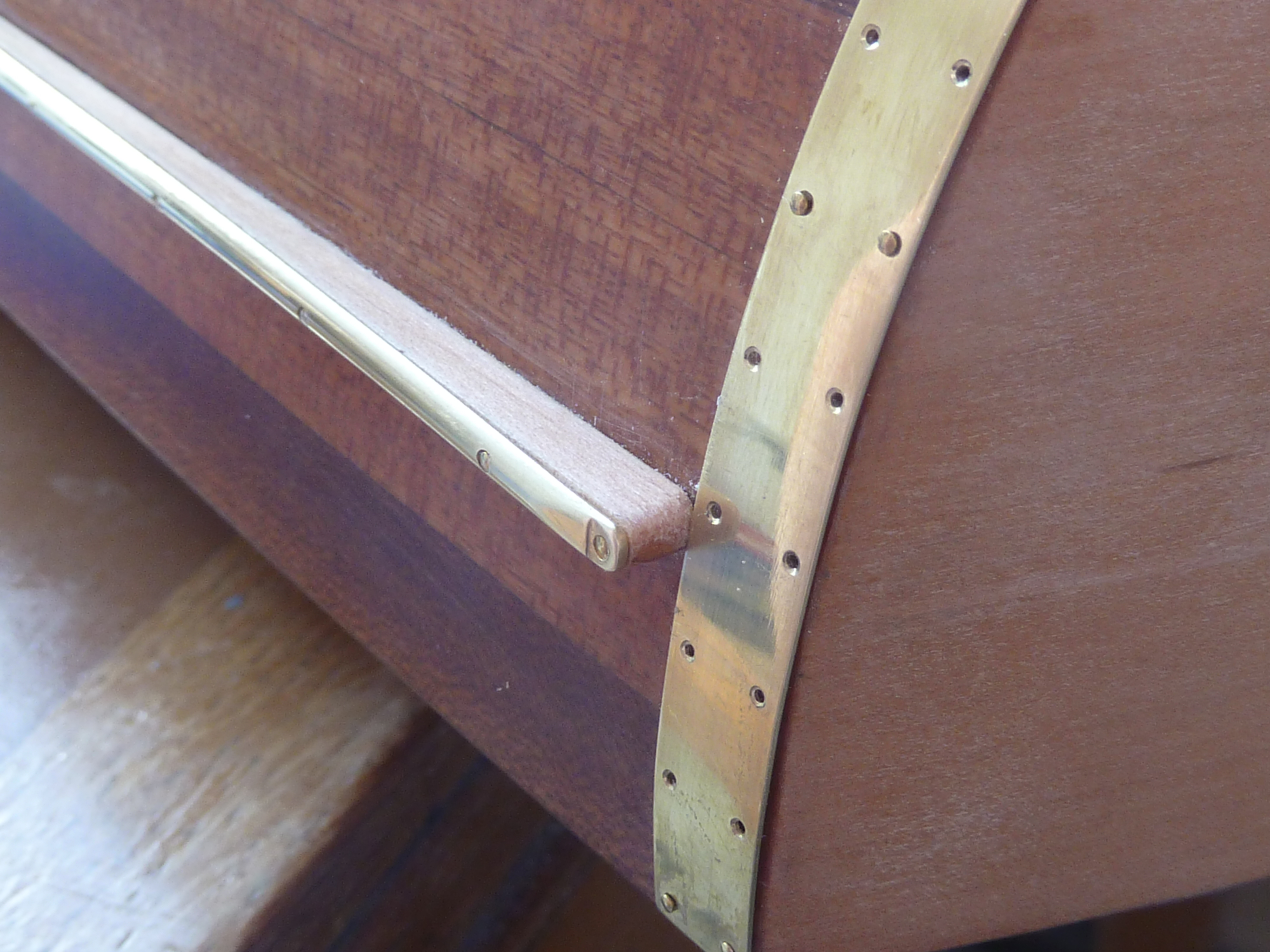
The blue tape is there to provide a reference line as it is easier to work to than one drawn on. The slight ridge of the tape gives you something to push up against when fitting the parts, The rubbing strip itself is 1/8″ half round brass from EKP Supplies in Devon. I’d liked to have obtained something more oval in section, but hours of searching on the net didn’t turn anything up in the scale I needed.
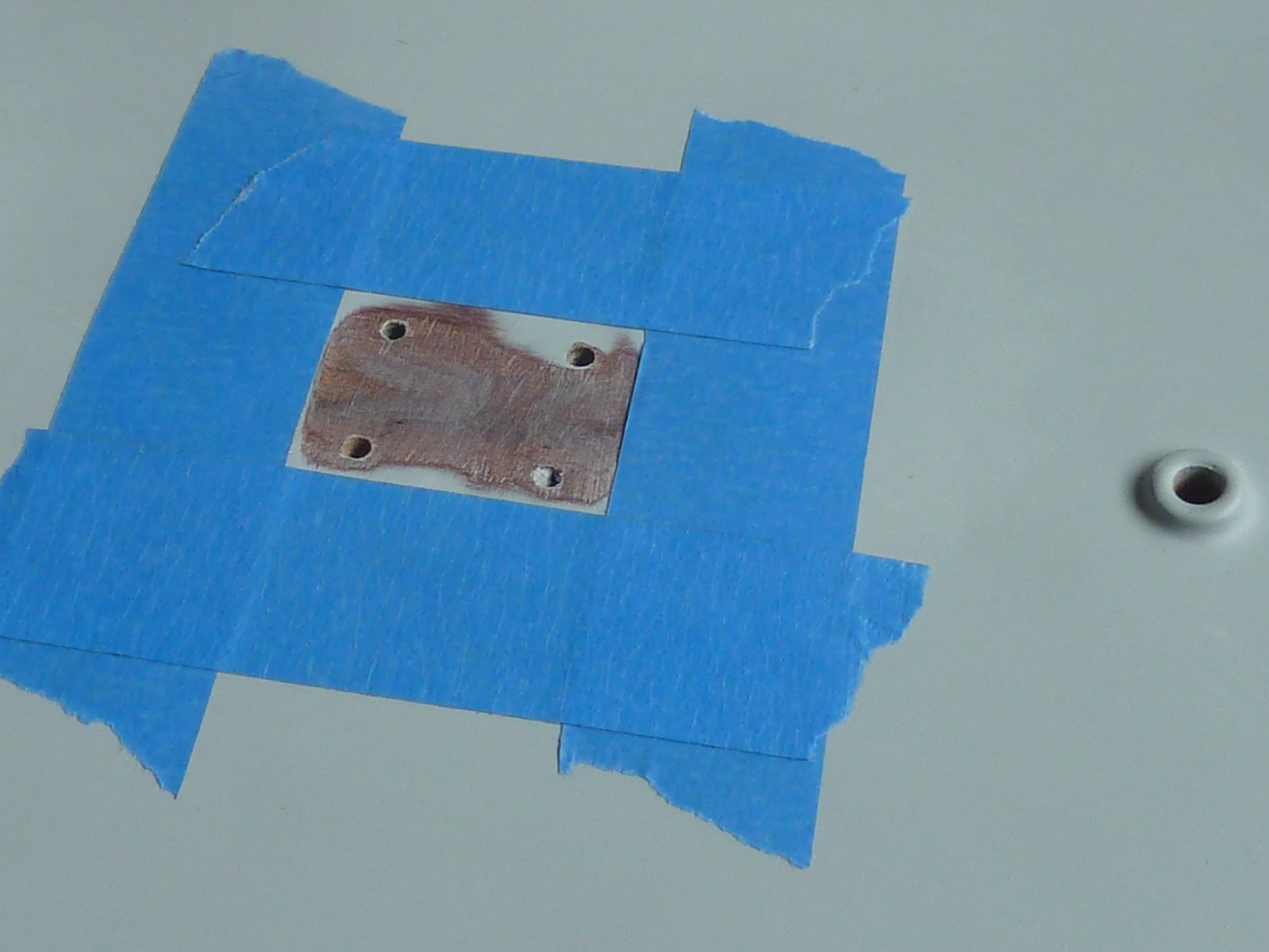
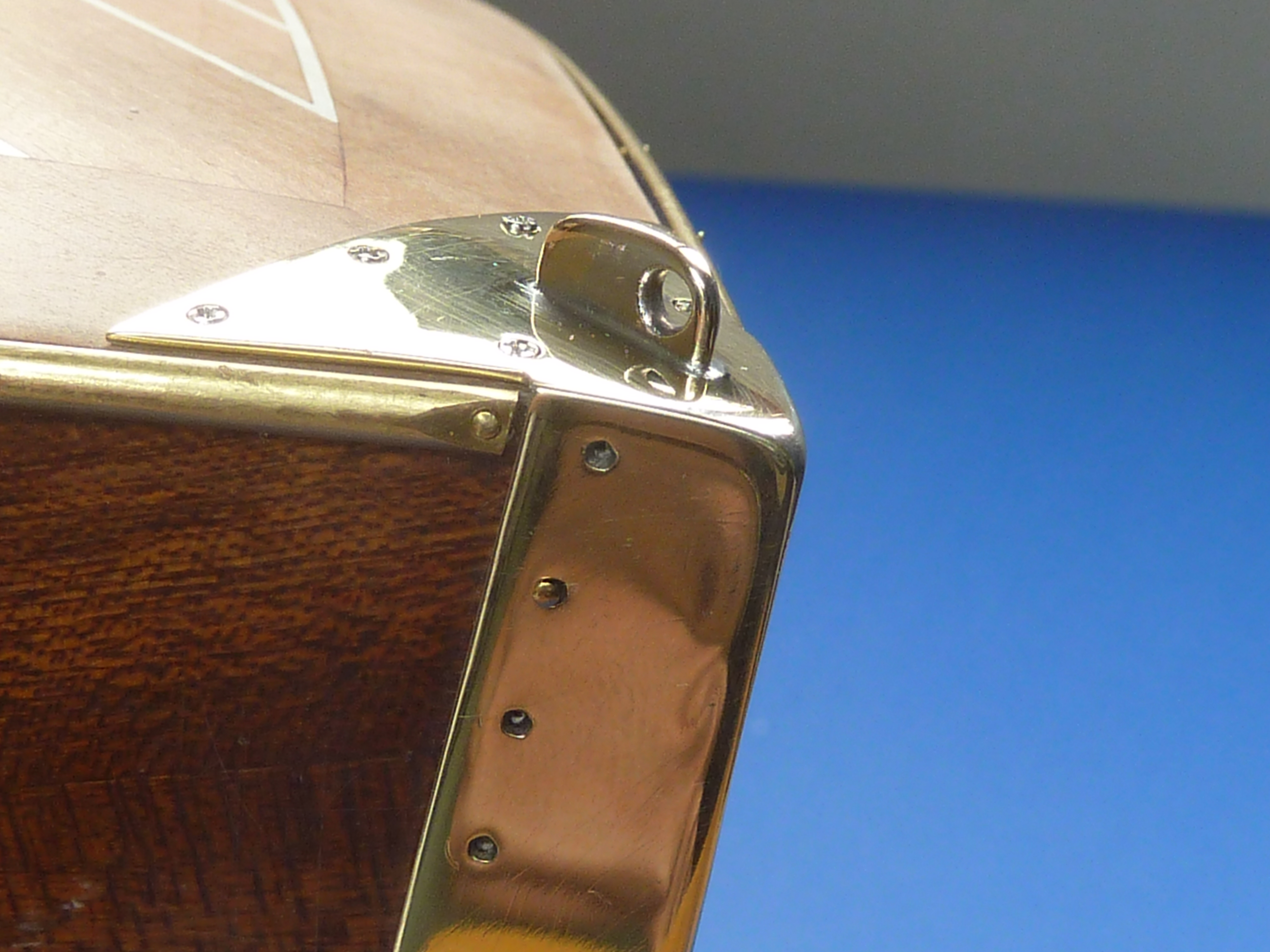
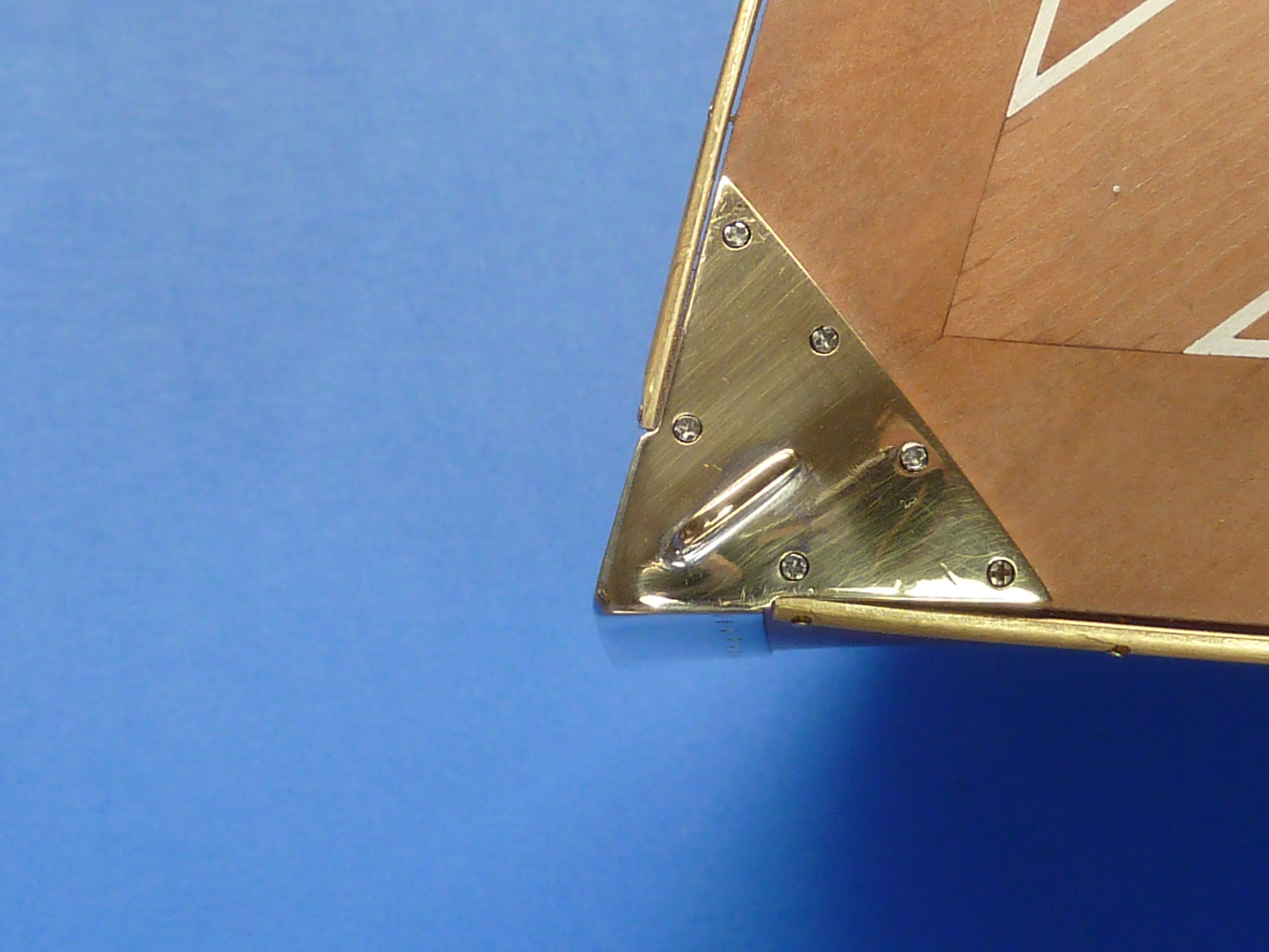
Prior to fitting the strip I made up the protection strips at the edges of the transom. They are an awkward shape to guess, so I put some more of my trusty blue tape on the area, cut the rear profile flush with the transom and used a pair of dividers to scribe a parallel line 8mm (1/3″)from the rear face. the tape was then peeled off and stuck onto some sheet brass as a cutting guide. The method worked well.
When the protection strips were added it gave me a reference for the rearmost edge of the fender strip. After being cut to length the ends of the fender strips were finished off and 0.6mm holes drilled at 20mm (3/4″) intervals. Dull, dull, dull.
Measuring and centre popping the holes in the fender strips. The “Miss Severn” on the cutting mat was the result of practising my gold leaf application, from which I learned that I’m not very good at it.
It was almost inevitable that I’d break a number of the 0.6mm drills as they are quite fragile, but thankfully only one of them actually broke off in the brass. It was however a bit of a sod to get out!
All of the brass items in the pictures have been dry/trial fitted. They will ultimately be bright nickel plated and the pins replaced with faux screws.
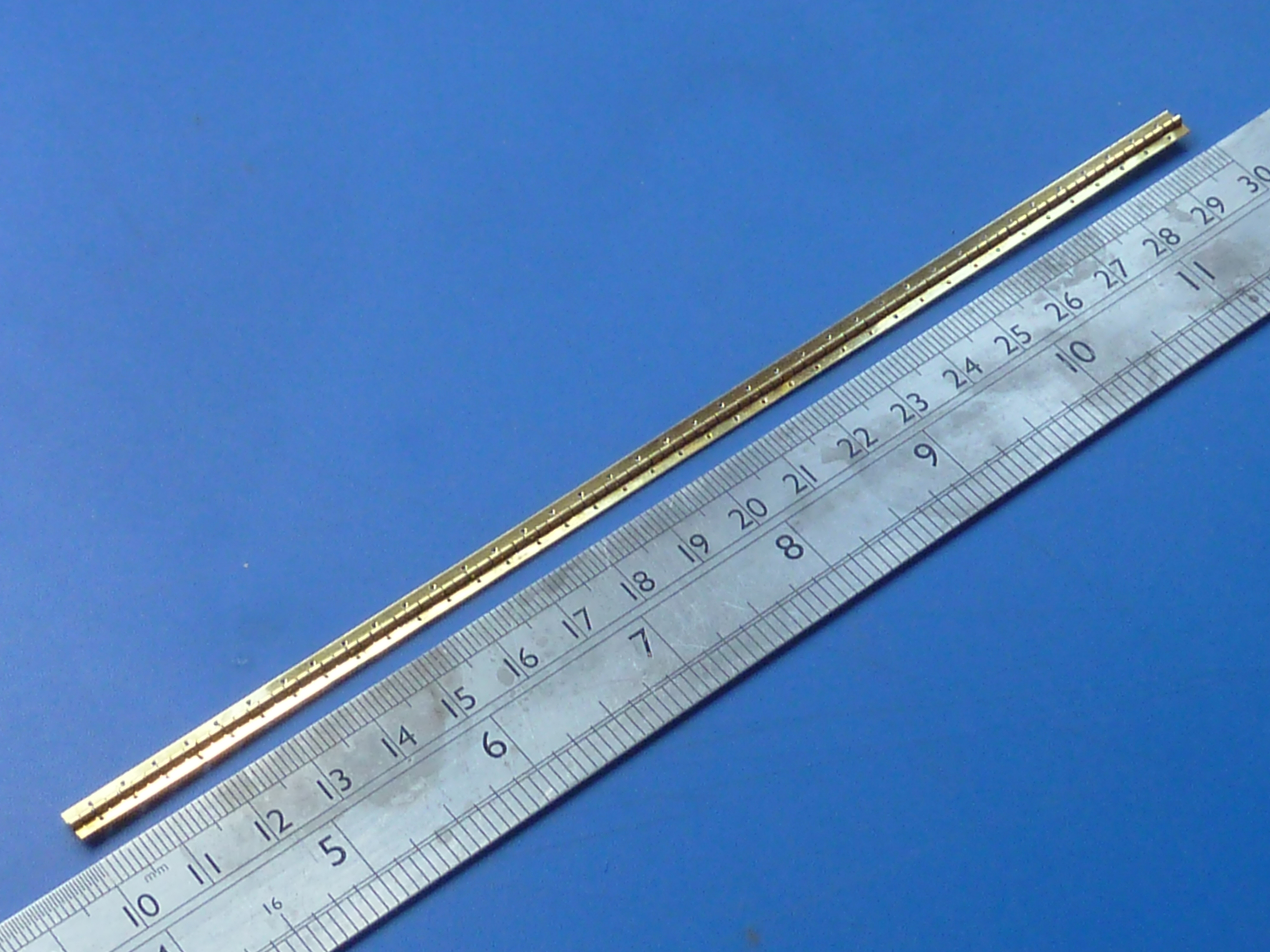
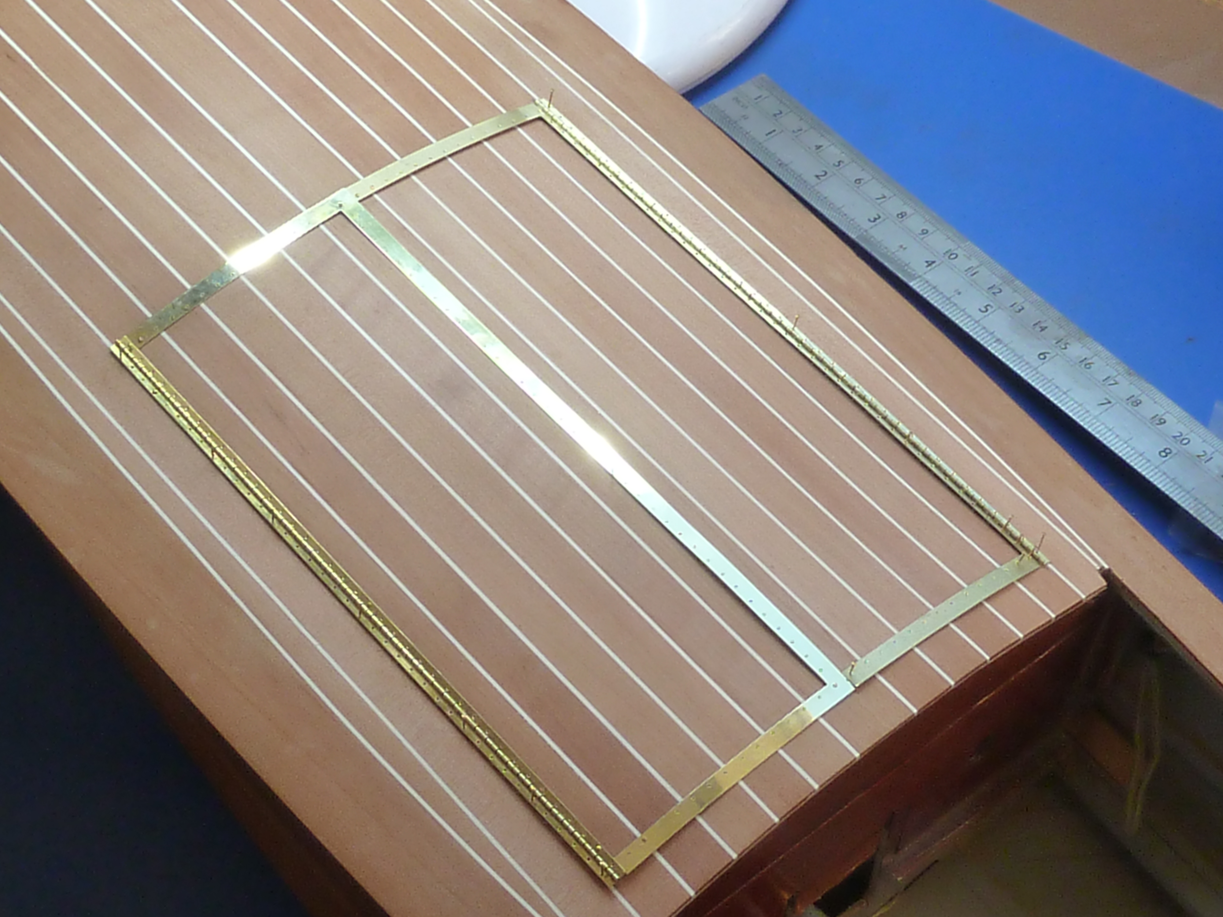
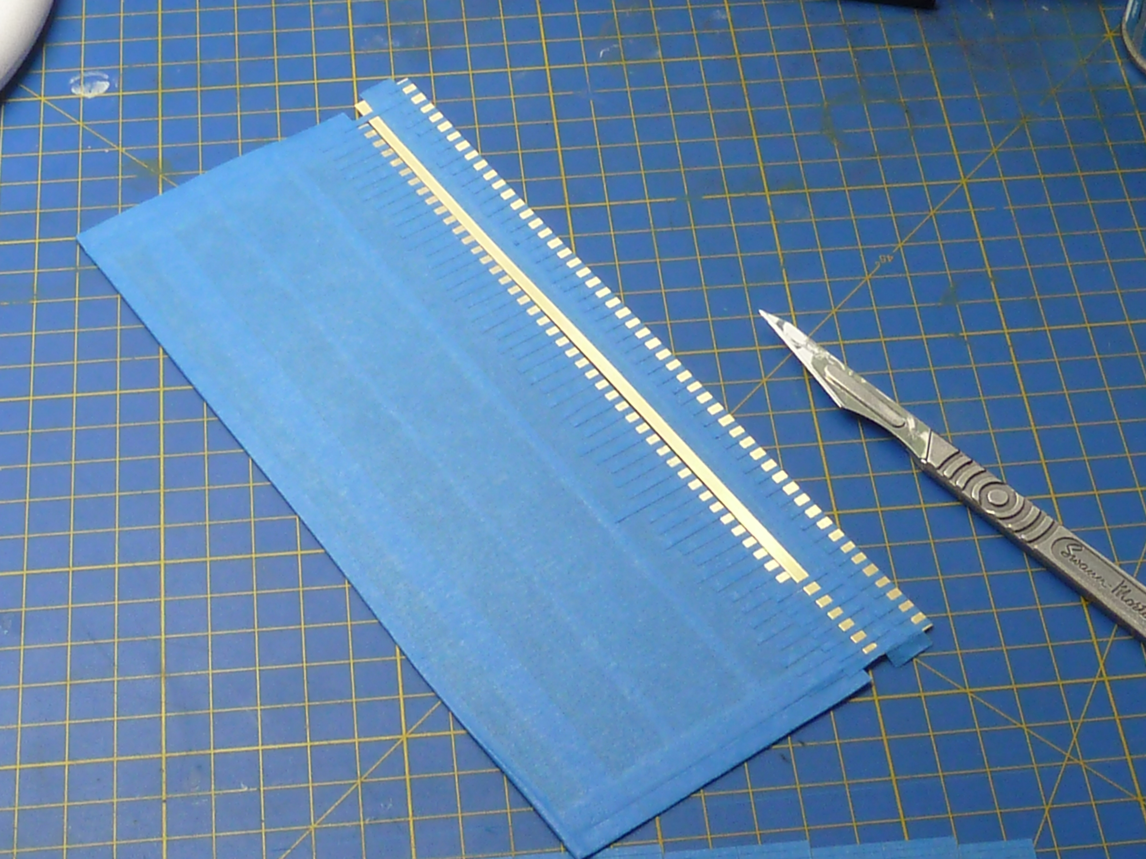
Next up was the sheerwater rubbing strip. This is just short of a meter (3’3″) long. It has 51 holes in it. Each hole has to be centre popped, drilled deburred and countersunk. There are two strips. And matching 0.5mm holes need to be drilled in the hull…
So that was 2 days of exciting activity especially when I was down to my last 0.6mm drill with more on order. As I can’t use power tools all the holes were drilled with a manual pin vice. Dull.
They look pretty good though.
I should’ve mentioned that I also fitted the cutwater to give me the forward reference for the sheerwater strips (80 more holes!). The version in the picture is the Mk.II. Even then the plate at the top wasn’t a stellar fit and was also too thin. The one one the real boat is quite a chunky item.
I glibly decided to remake it in a thicker section. The combination of the thin cutwater sheet and thicker fairlead plate proved a real trial to solder, particularly as I don’t have solders of different melting temps. Having wasted half a day trying to solder it in accurately whilst not unzipping everything else, and failing, I decided that some form of jig was required, One that could withstand my cook’s blowtorch on it.
Whilst mulling over the problem in bed, I recalled I had some Plaster of Paris in the garage that I bought for some long forgotten project and never used…
Next morning I super glued the cutwater together with CA glue and stuffed it in some Plaster de gay Paris and left it to set for a couple of hours. Et voilà! Un soldering jig (anyone remember Miles Kington’s Franglais column in Punch?).
The CA glue was removed from the cutwater and the whole thing soldered up in the rather rough and ready jig. Which worked. It still took a couple of goes to get it good enough though.
The plate still needs a proper polishing to get all the scratches out prior to plating.I know the sheerwater rails aren’t right. they’re only tacked in place for now.
That brings you up to date on the hull work so far.
I have also done a little work on the engine bay doors which will need to be in place for the staining operations if they are to come out the exact same tones. The insides have been stained and varnished, and the cross braces fitted in a contrasting colour of boxwood.
Now I really do need to get onto the staining and painting ops.
Well, this post has been delayed a bit more than I expected, but I’ve been taking a bit of time off to do the ill thing again. They don’t hand out medical retirement to anyone. You have to work at it constantly. Hence, the modelling activity has dropped off for a while, though I have been able to do some background CAD work for some other modelling projects which may appear in the future.
I’m back at the modelling table now though, so hopefully normal service will be resumed.
In my last post I left it with a hinge that I’d made for the engine bay doors being malformed. Despite trying, the thing wasn’t recoverable and I ended up having to photoetch another. Given the time and faff of making these pieces I think I might invest some money (aka known as spending) and get a professional etching house to produce me an A5 sheet packed with the things. It will save me a lot of time, effort and angst in the future.
A hinge. Made properly.The hinges mocked-up on the model. Almost 500 hundred holes ended up being drilled to fit these things! The pitch of the hinge leaves is about 2mm.
Apart from the bright nickel plating, that is the hinges complete. I’ll plate them when I am doing some other plating work.
Having completed the hinges I moved on to sorting out the engine bay and preparing everything for the installation of the engine and various other components. They won’t actually go in until I have finished sanding down the hull though, because of the dust.
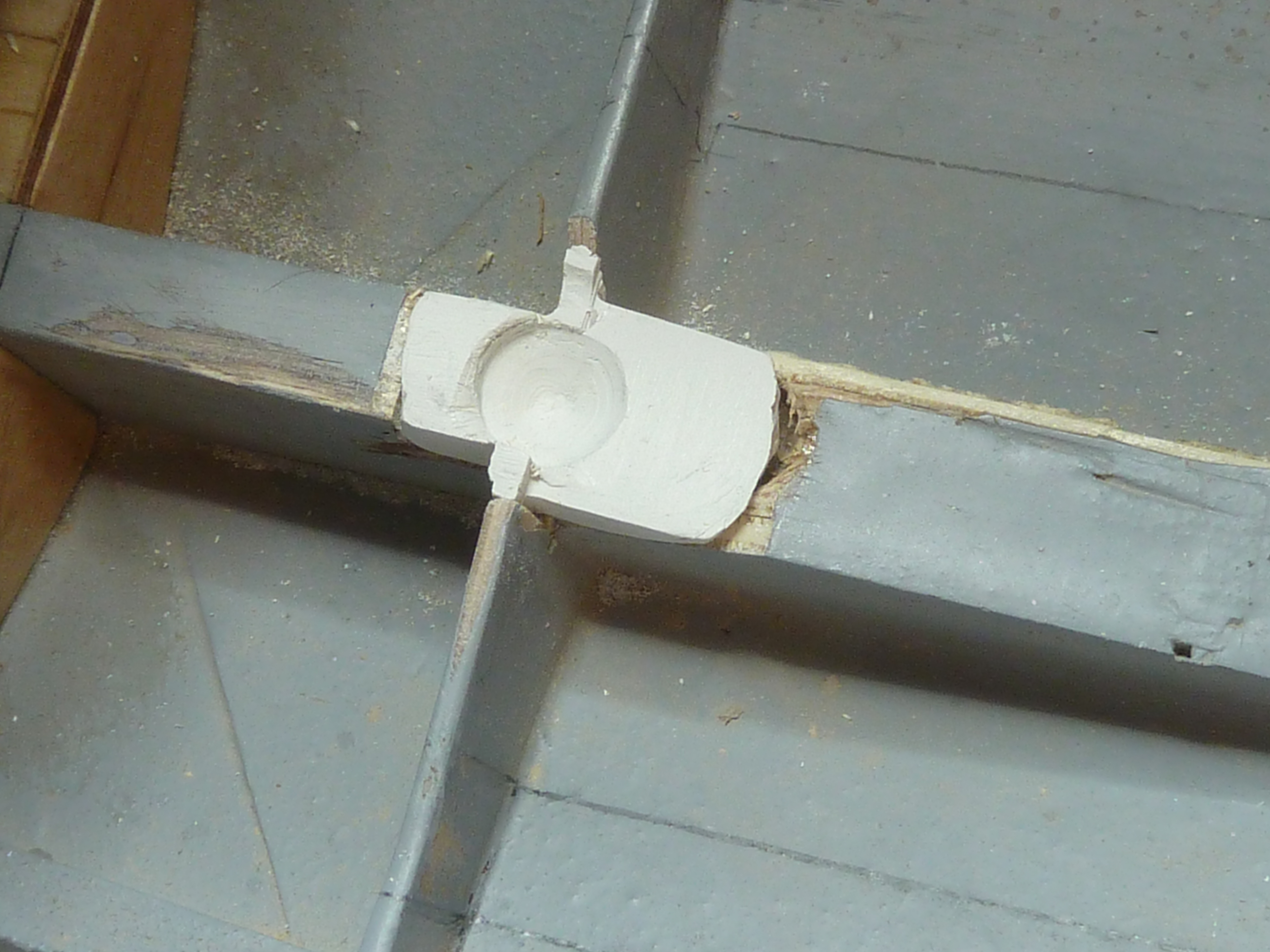
First up was filling the unsightly hole dug out while I was trying to fit the mock-up engine. You won’t actually be able to see this when the engine is in place, but I can’t leave it like it is. It’d irritate me too much.
I mixed up some super fine white Milliput and wrapped it in some clingfilm. Then I pushed it into the hole to be filled and used the mock-up engine to press in the voids required to accommodate it.
Milliput wrapped in clingfilm
Once the Milliput had cured it was removed from the model, unwrapped and filed to the final shape, including adding some relief to the indentations for the engine.
Clingfilm removed and cleaned up.
Here it is back in the model. It will eventually be epoxyed in place and any remaining gaps filled with modelling filler.
Back in situ. The remaining gaps will be filled with filler.
Having painted the engine mounting I’ve finally got around to attaching the engine to it permanently. I had briefly toyed with the idea of actually using the mounting bolts to hold it in place, but trying to get all the studs exactly lined up with the holes was a challenge I ducked.
Instead the engine subframes were glued to the mounting using epoxy glue and the studs glued in afterwards. This also means it is quite easy to get all of the threads showing above the nuts an even length.
Engine mounting studs glued in place.Studs awaiting the installation of the gearbox. The pegs are there to hold the subframe in place while the epoxy glue cures.
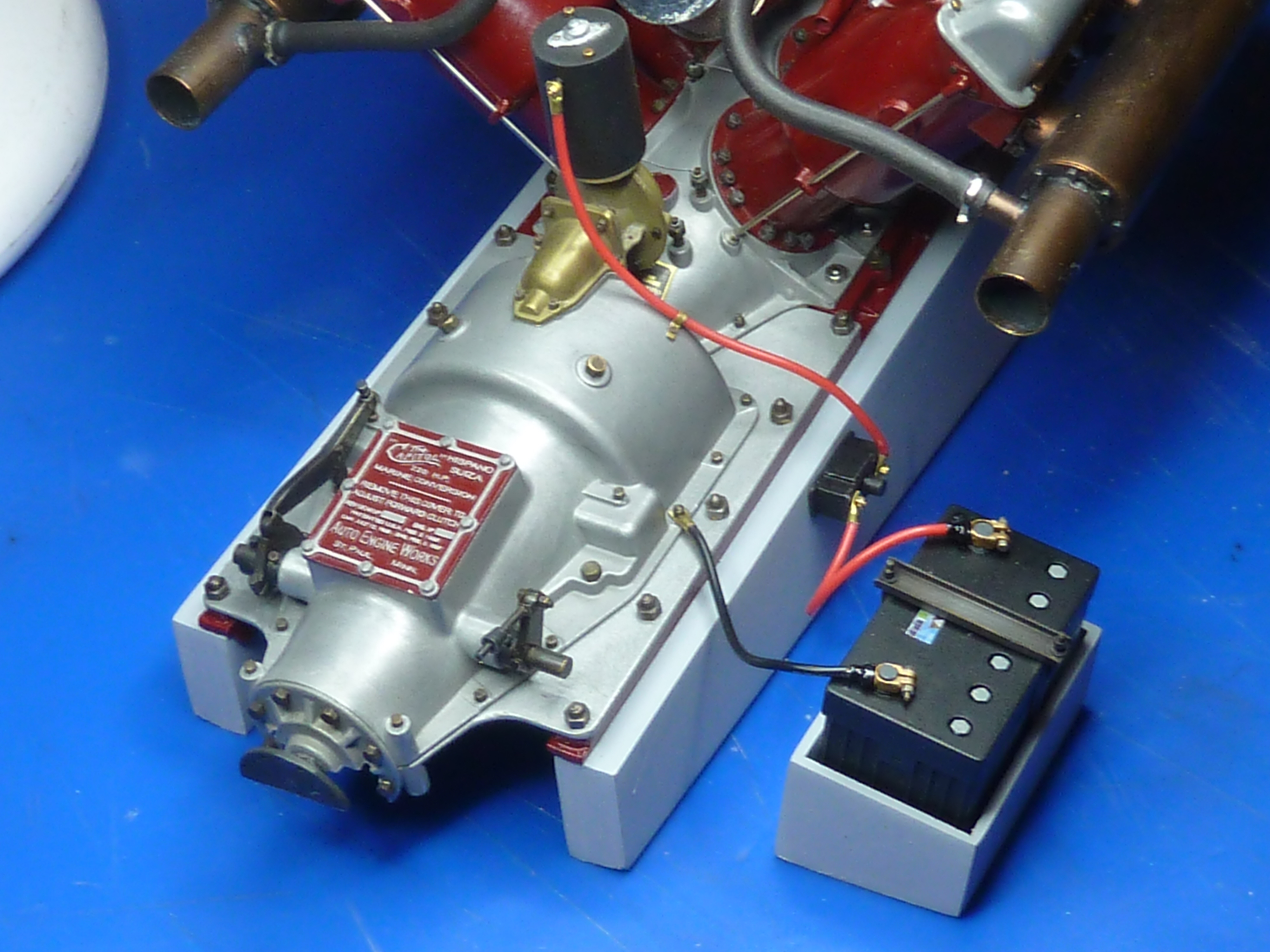
With the engine mounted properly on the frame I could get on with finalising some of the smaller installations and connections. Mainly wiring. Below is the starter motor wiring installation. A small ‘solenoid’ has been made from plastic stock.
The oil lines to and from the tank have also been mocked up on the bench. The idea is that I will fit them to the engine prior to it being installed. The pipes can then be fed into the oil tank when the engine is in the model. There is free space within the tank so the length of the pipes won’t be critical.
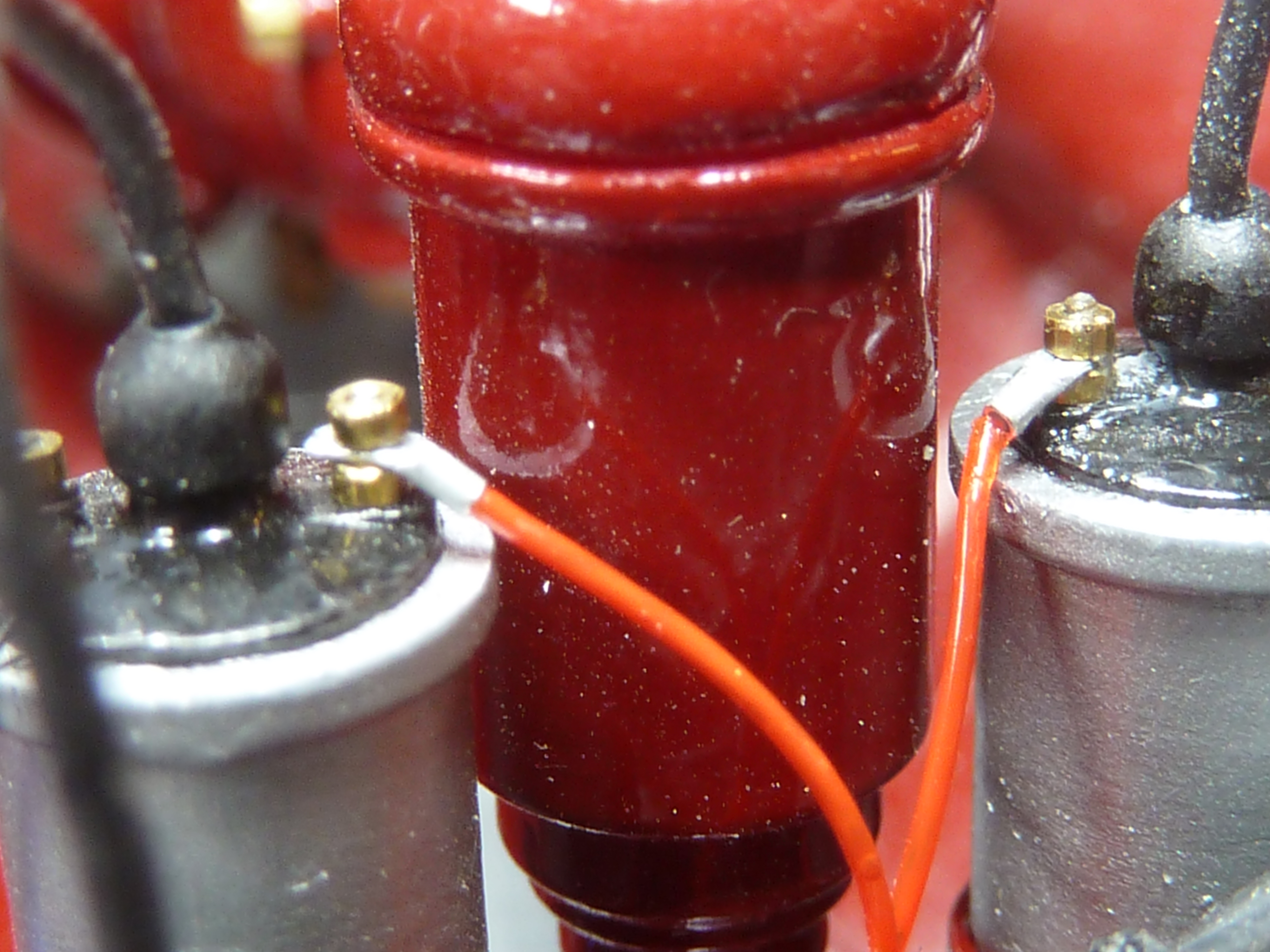
Red fishing line has been used to connect the positive sides of the coils up. The nuts are M0.6.
Note to self: remember to dust the damn thing before you photograph it.
One other significant development at MBIQ Mansions has been the acquisition of a ‘4k’ resin 3D printer. A Phrozen Sonic Mini 4K to be exact. The 4K refers to the resolution in the XY plane which is 35 microns, or in good old inkjet speak, 722dpi. (1 micron=0.001mm or about 0.00004″)
I think the output from the printer is quite amazing. They are a bit temperamental though, and take some trial and error with settings to get going well. There is however a very helpful forum of other users to refer questions to. I’ve also invested in an Anycubic print washing and curing station, which I would highly recommend as it makes cleaning the prints so much easier. Also invest in lots and lots of Isopropyl Alcohol and kitchen paper towels…
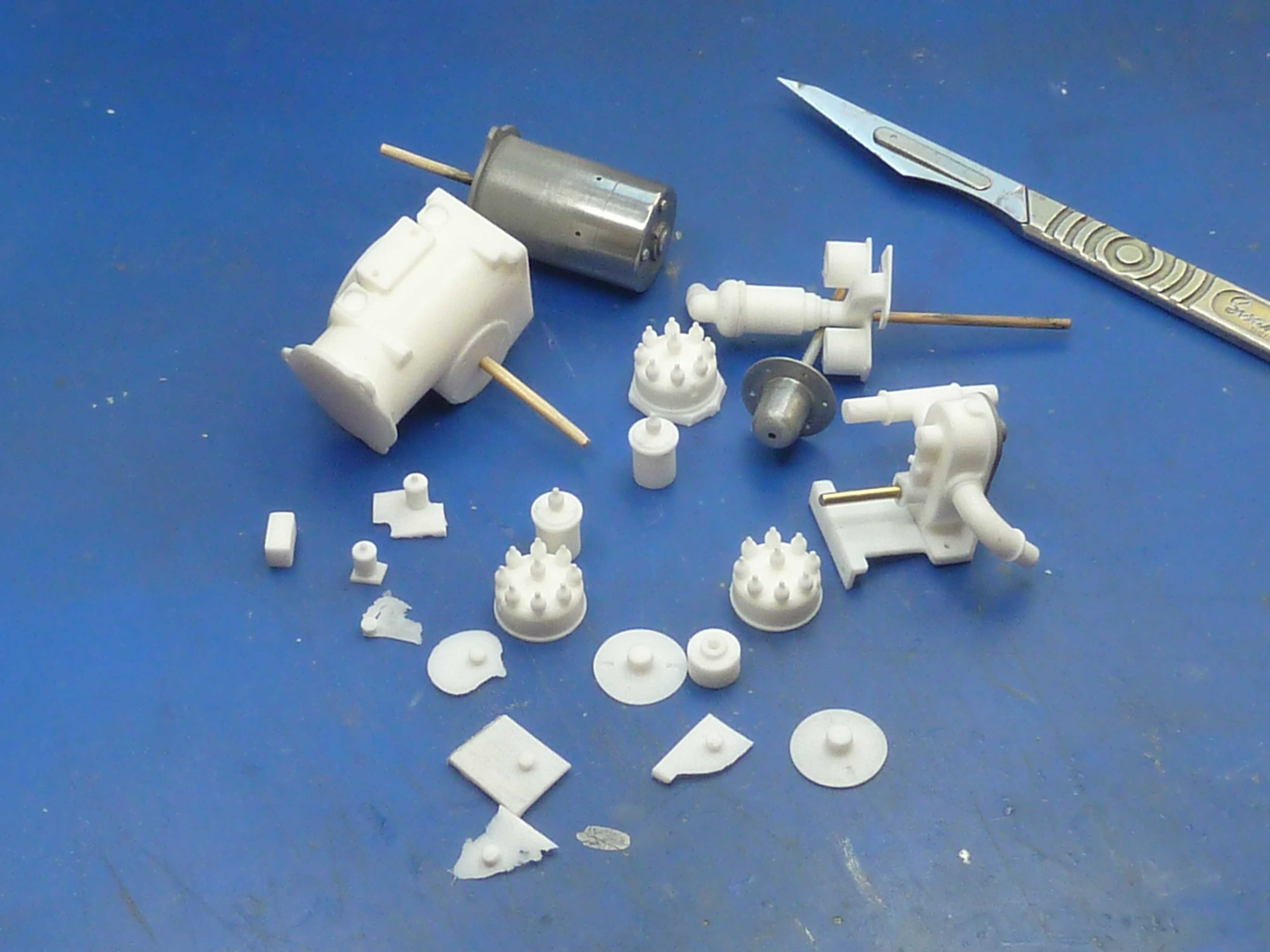
Below is a sample of the printer’s output. Clockwise from top left:
35 micron Output from the Phrozen Sonic Mini 4K machine.
Print at 50 micron resolution from a professional print house .
British tight-wallet’s preferred stamp.
Another Phrozen output which was subject to overly aggressive cleaning before being fully cured. Hence the bits of text broken off. Lesson learned!
I’ve used the printer to produce a selection of P-clips and connectors for the wiring looms on the model.
While I was ill I also took the time to knock up a notional wiring diagram for the model to allow me to visualise what wires should be going where. The idea being that the wiring installation should bear some relation to reality when installed.
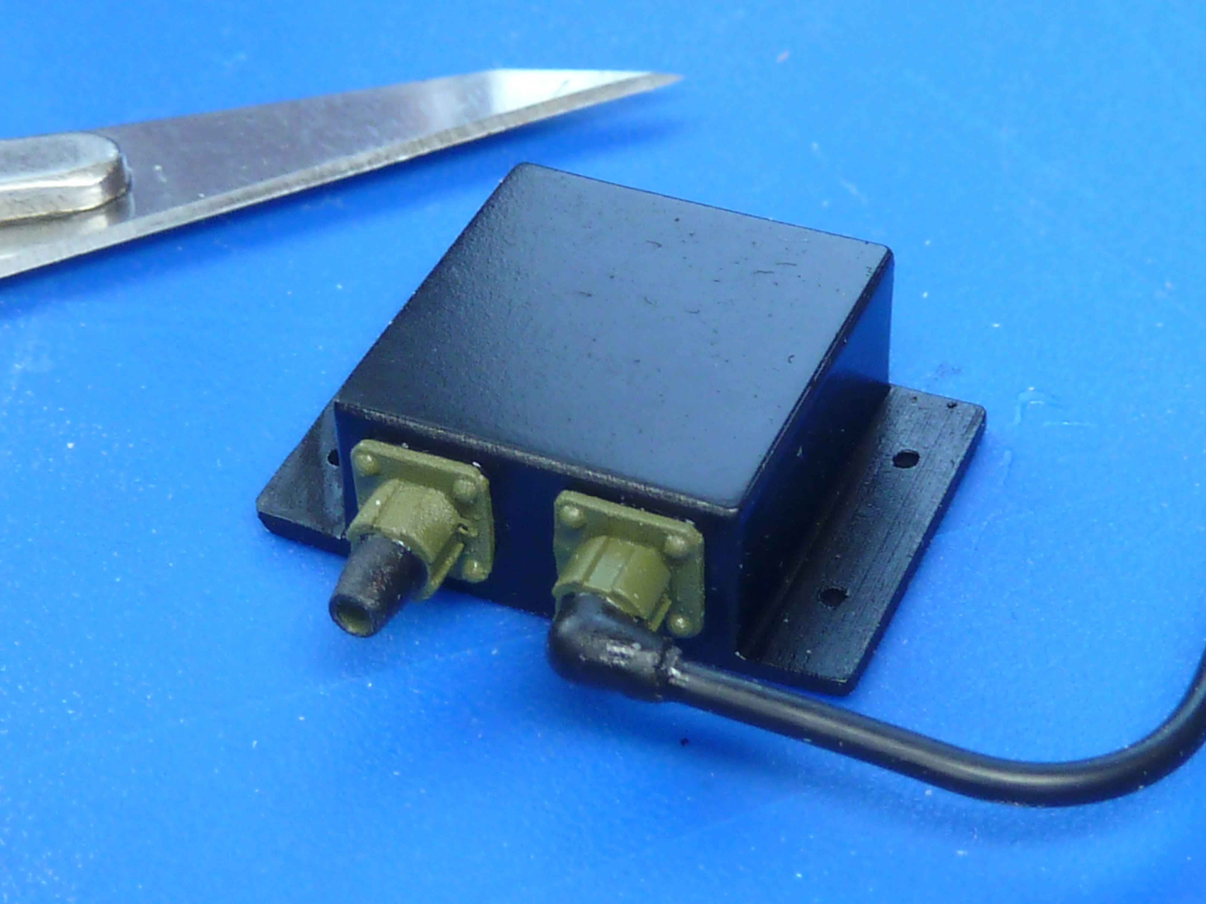
The 3D printer also allowed me to produce some electrical junction boxes in various sizes. For what it is worth, and in the absence of any other information, I’ve gone for a Raychem style of wiring loom with Mil-DTL-38999 connectors. Those were the ones that we used to use on the aircraft and I always thought they looked quite tidy.
Notional wiring loom for the engine. There isn’t much wiring at all on this era of engine though.
The clutch mechanism has also been finalised and a hole drilled in the bulkhead to accommodate it. A piece left over from the Hasegawa Clerget 9F push rods makes a nice simulated rubber grommet. Well, it will when it’s painted black.
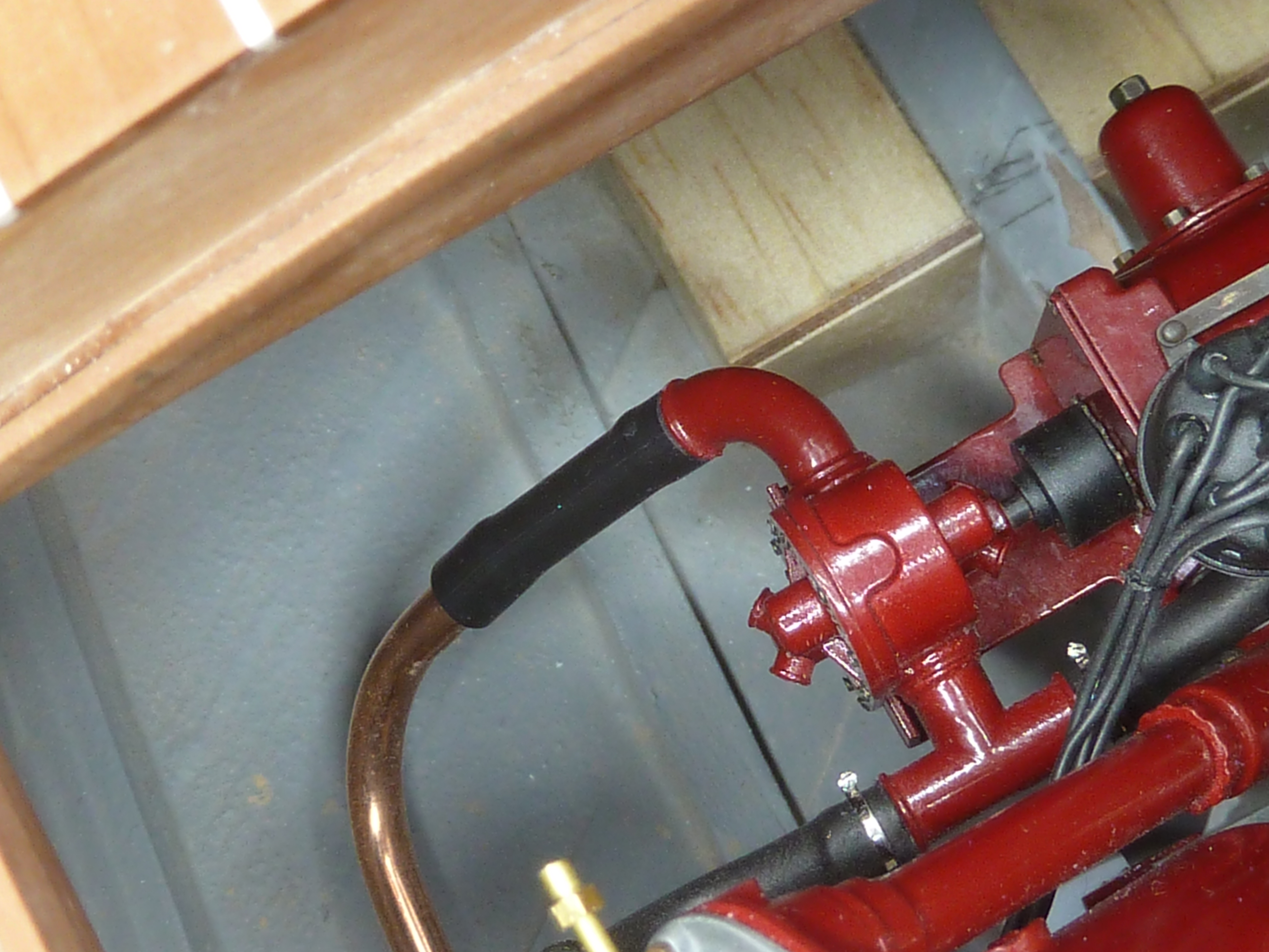
The copper pipe for the main water feed has been manufactured and trial fitted, including saddle clips etc. The connecting pipe to the engine has been deliberately made a little slack on the pipe so that it will be easy to slip over when the engine is finally installed. The jubilee clips have yet to be made.
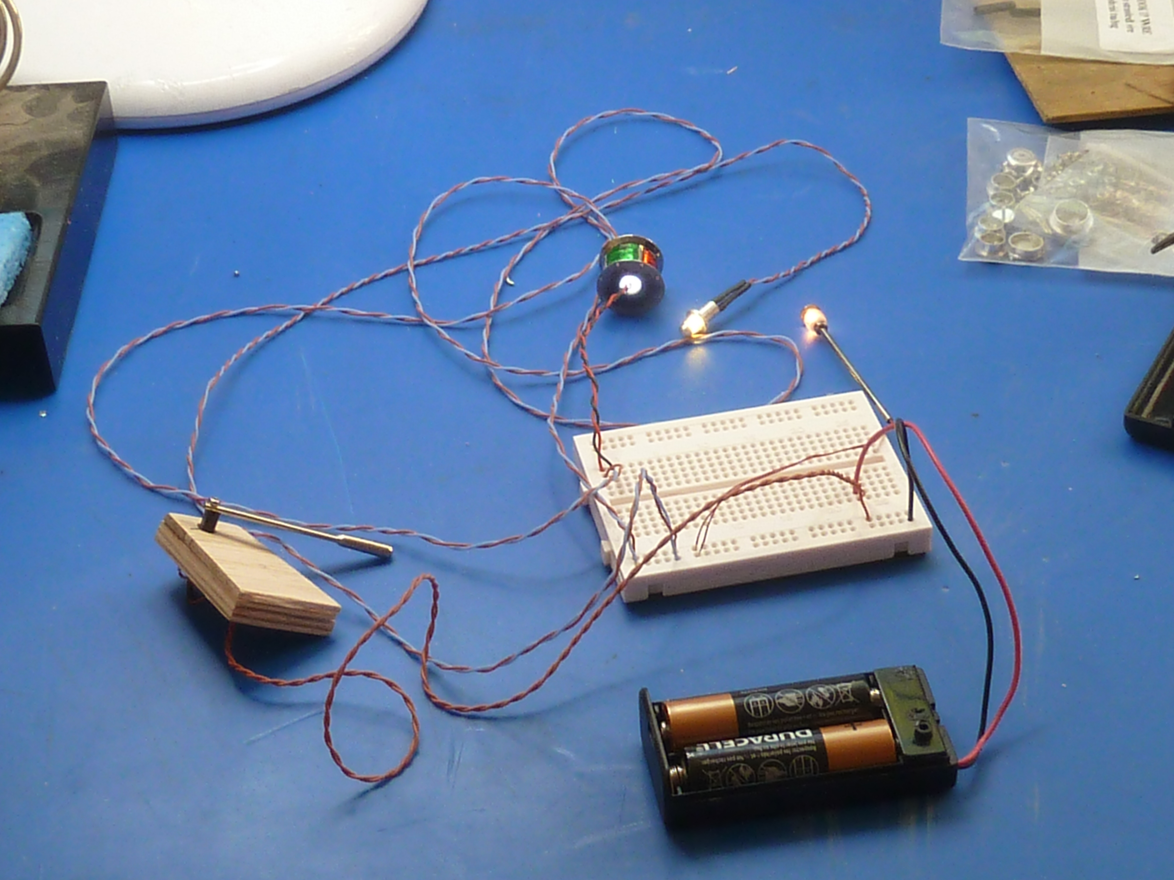
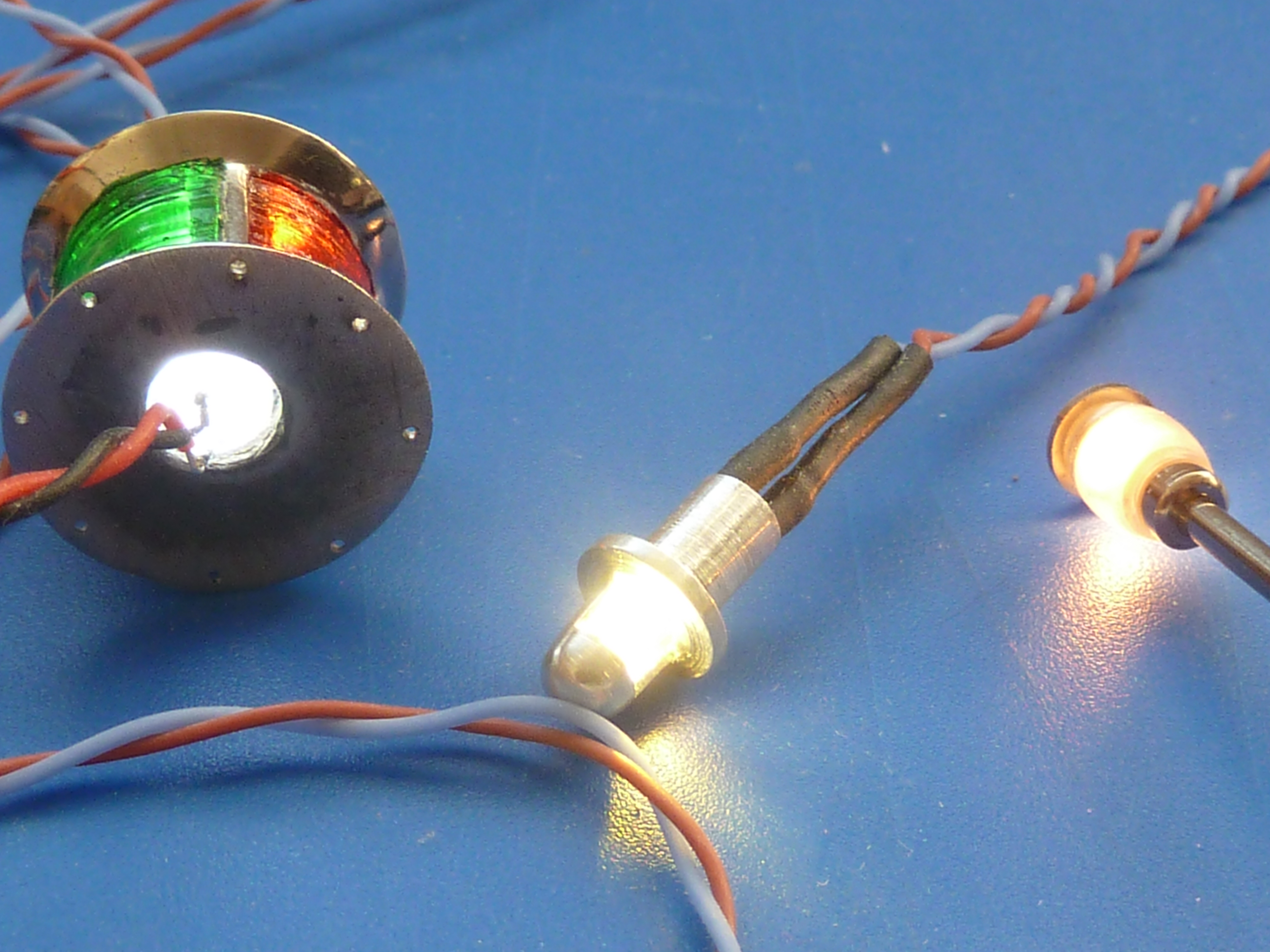
I initially used the wiring provided in the kit to connect up the various lights. However, it was very heavy duty, not that flexible and technically complete overkill. I’ve finally got fed up with it and replaced it with some much smaller gauge PTFE coated wire which is much nicer to work with and a lot more flexible. Just to make sure that the thinner wiring wasn’t going to cause problems with voltage drop I mocked up the wiring on a breadboard before it was installed
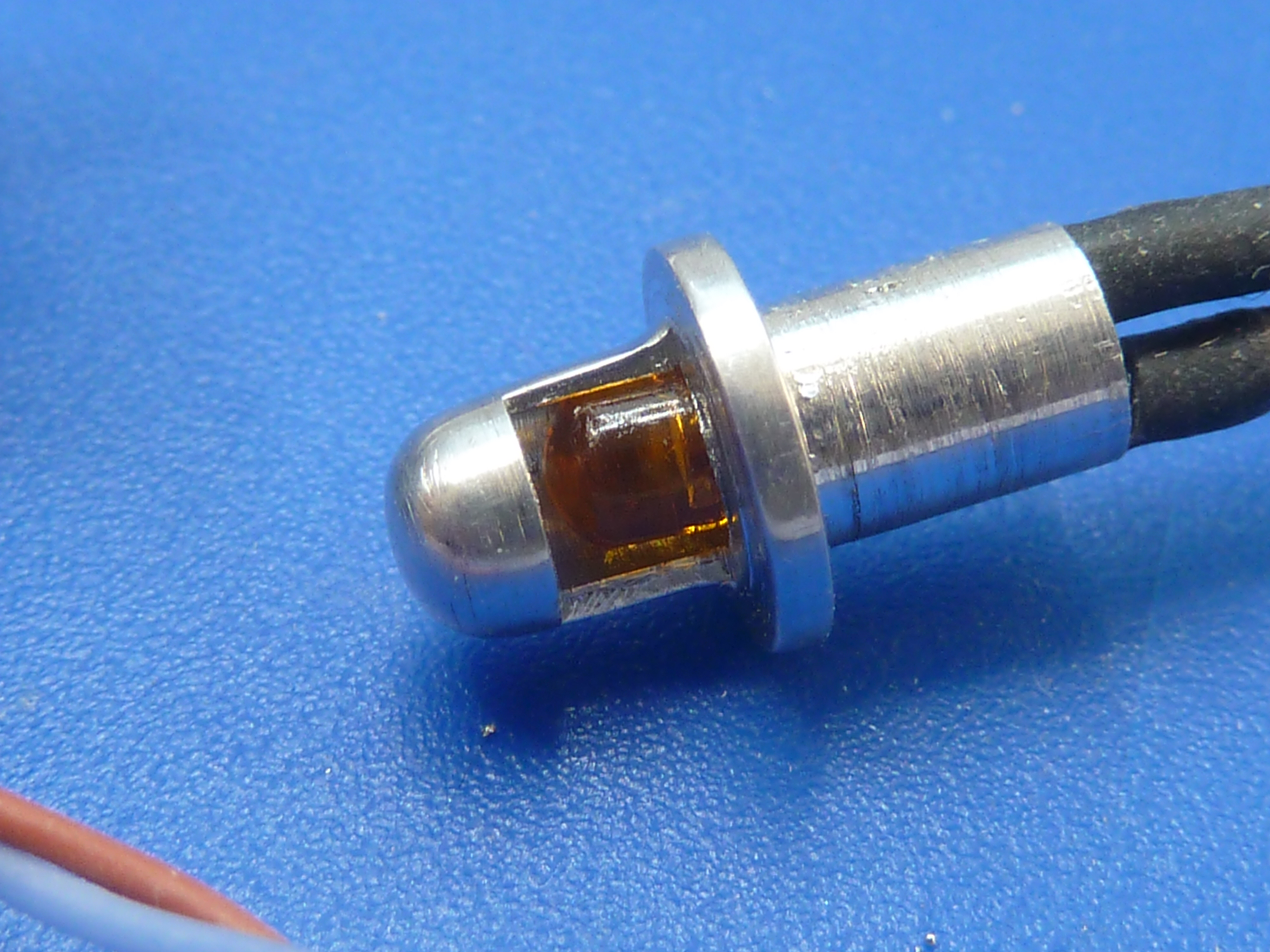
I’ve also replaced the rice bulb lamp in the dashboard with a 3mm LED. These lights won’t be easily replaceable if they fail and the LED should be much more reliable as well as drawing less current. The LED was a hard blue/white light though, so I painted it with some clear orange to give it the same colour temperature as an incandescent bulb.
L-R Hard white LED in the bow lamp. Hard white painted with clear orange. True incandescent bulb.
The 3D printer has really opened up a world of opportunity for me in my modelling. It’s immediately become my goto solution for many bespoke items. It’s much faster for me to bang something out in CAD and print it than make by hand. The results are higher quality too.
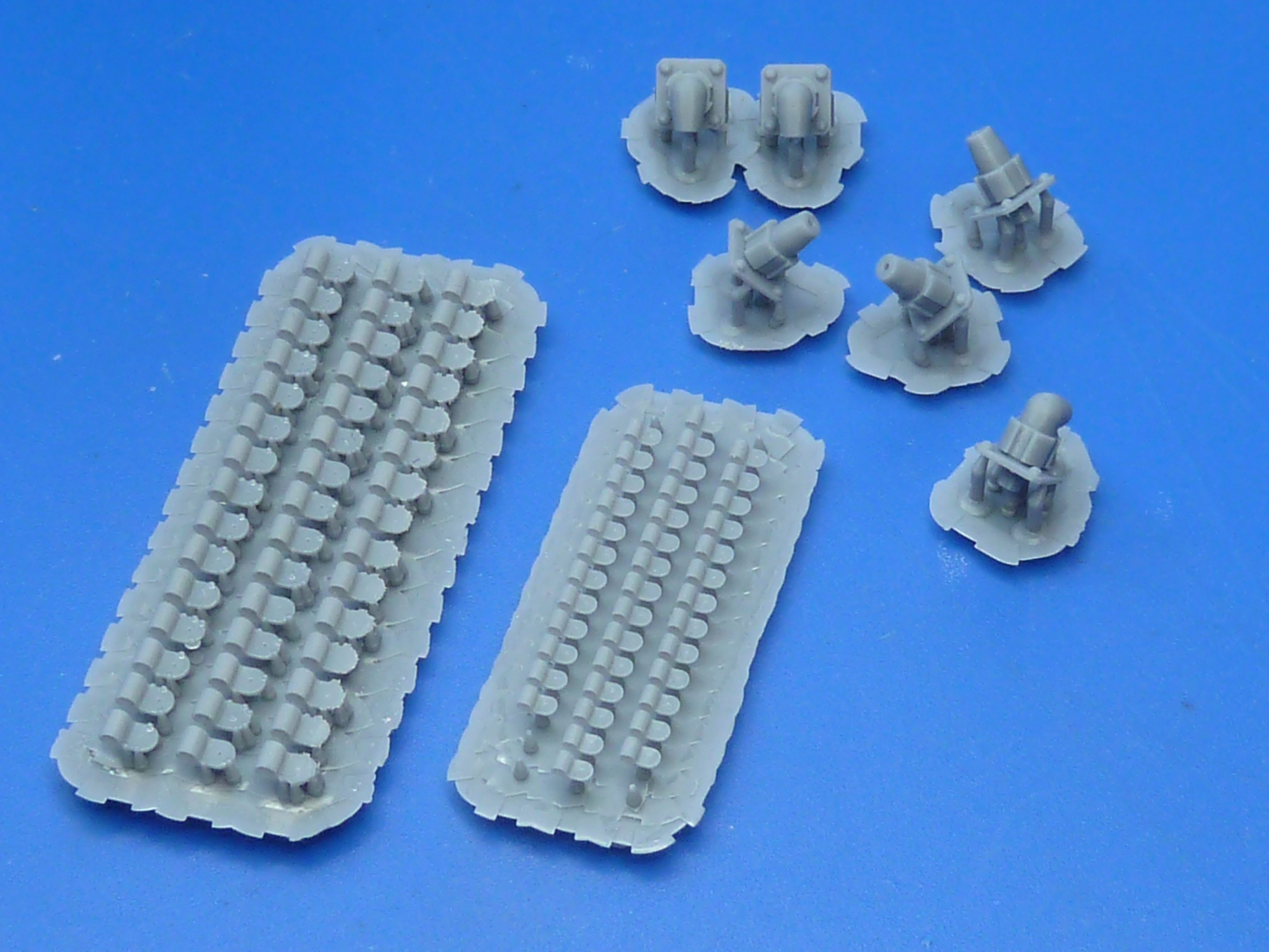
Fire Extinguisher and cone, with a few more P-clips.
Fire extinguisher mounting bracket.
The fire extinguisher was a fun item to make. The 3D print needed a little sanding smooth before painting and a custom decal had to be made, but the final result is quite pleasing. The handle is made from a ready meal tin’s foil. I didn’t think the printer could handle the thinness required.
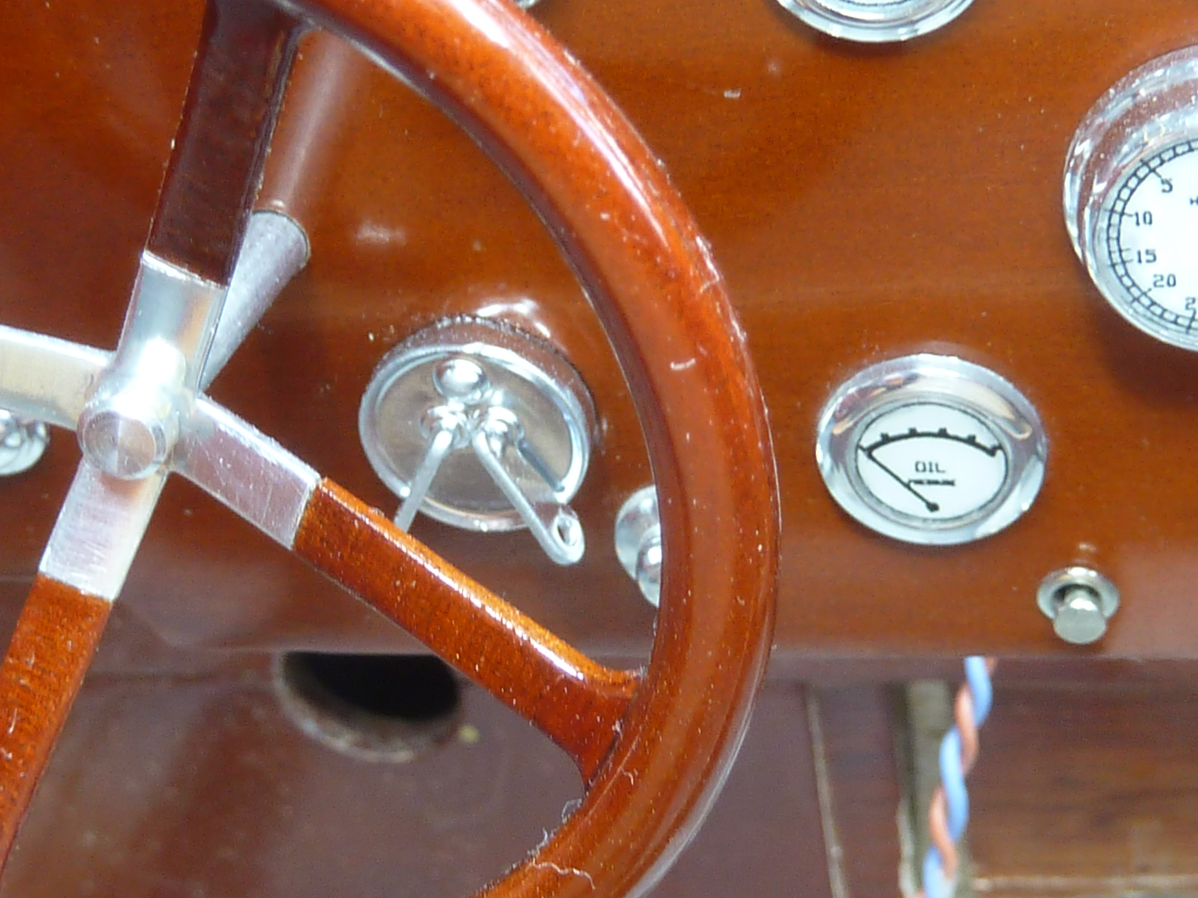
After the break in progress, and to get me back into the groove I went for a quick hit activity and decided to assemble the dashboard. Having done that and trial fitted it in the model I discovered that the steering mounting hole suggested in the Mack kit was a little low for my liking. The steering wheel is quite high in the real boat, but quite low in the model. I marked and drilled a new hole which was where I wanted it, but that did leave me with the problem of the unsightly old hole.
Fortunately the real boat has an additional switch which has been omitted from the kit. I had wondered what I was going to do about it, but it proved a fortuitous way of covering up the unwanted hole in the dash. You can see the switch I mean immediately to the right of the steering column in the photo below.
I’m not at all sure what the switch does or even looks like in detail as the picture above is the only one I have of it. However a PASWAG* design was produced and printed.
*Pure and simple wild arsed guess.
Here it is fitted in the dashboard with the revised steering column hole above left.
Trial fitted in the model with the steering in place. It’s still a bit low, but to change that would require extensive mods.
I did think about trying to cast the switch, but decided that the thin sections were just too much, and I wouldn’t get the alloy to flow in them. However, I have recently come across some quite amazing silver paint which gives one of the most realistic ‘chrome’ finishes I’ve seen.
To be honest it’s not actually paint at all. It’s an ink. Molotow make some Liquid Chrome pens which are themselves quite stunning, and they provide refills for them. The refill ink is easily airbrushable straight from the bottle.
The other major activity I have finally embarked upon is the sanding down of the hull. This is a task that I dislike, quite a bit, but is a vital part of boat building so has to be done. I also have to do it in batches because of the noise it makes, and I don’t get on with noise at all. It’s a slow process but is about 50% done now. Once it’s done that way will be clear to start staining and varnishing the model.
Having finished the engine diversion it was time to get back onto actually building the Miss Severn model. Not surprisingly these activities have focused around the engine bay and installing the new engine model in there.
In order to try out ideas and plan the installation of components, without the need to constantly handle the engine, I reverse engineered a CAD model of the boat’s hull and installed the virtual engine within it. That allowed me to quickly try different layouts of equipment.
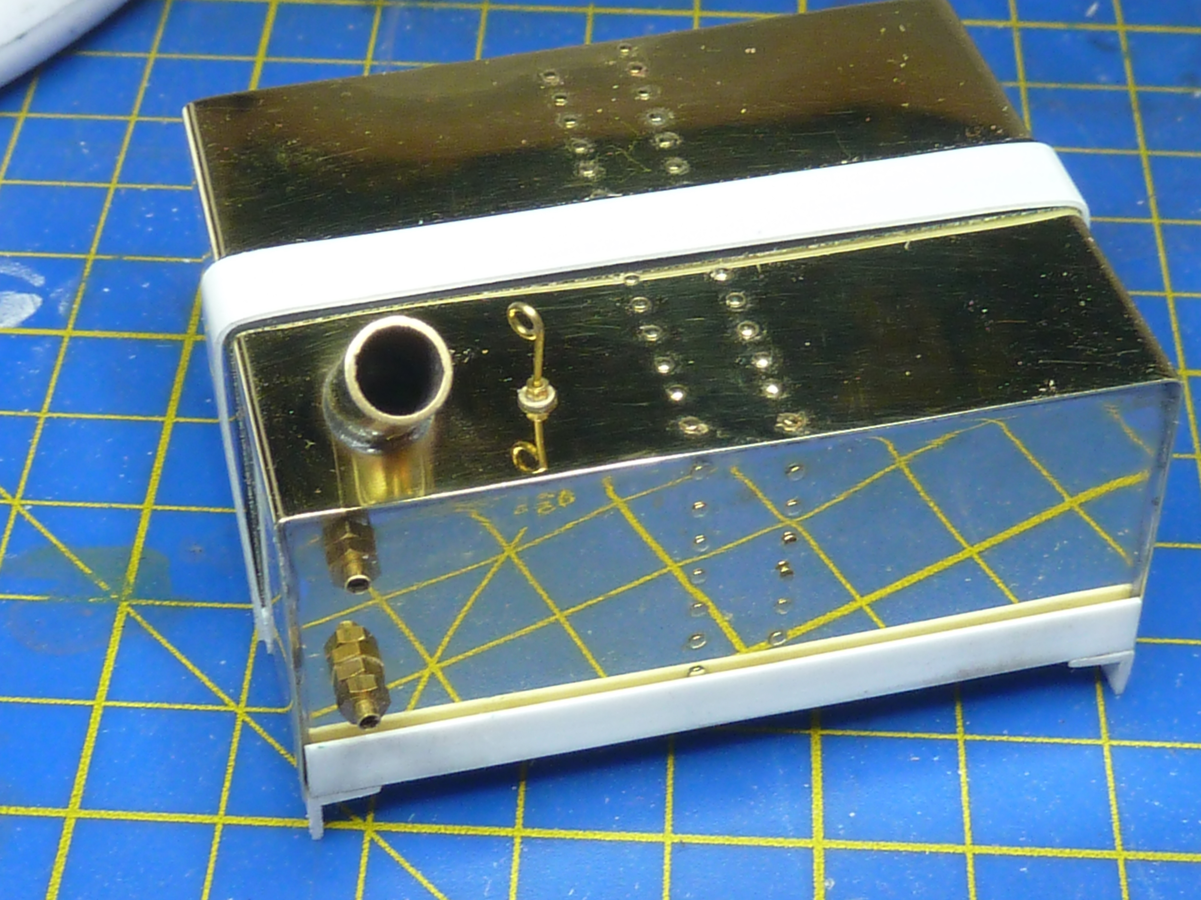
One of the first activities was to manufacture an oil tank for the bay. I’ve no idea what size the Hispano engine requires, but I do know that the Hawker Hurricane with the Rolls-Royce Merlin had a 7 gallon tank. If it was good enough for Sydney Camm and Rolls-Royce, it’s good enough for me.
A quick box tank design was sketched out with the requisite scale volume (~2.2 fl oz since you ask) and some brass sheet cut and bent into to two C sections to form it. These were then soldered together, which was not the easiest thing as I’m no coppersmith.
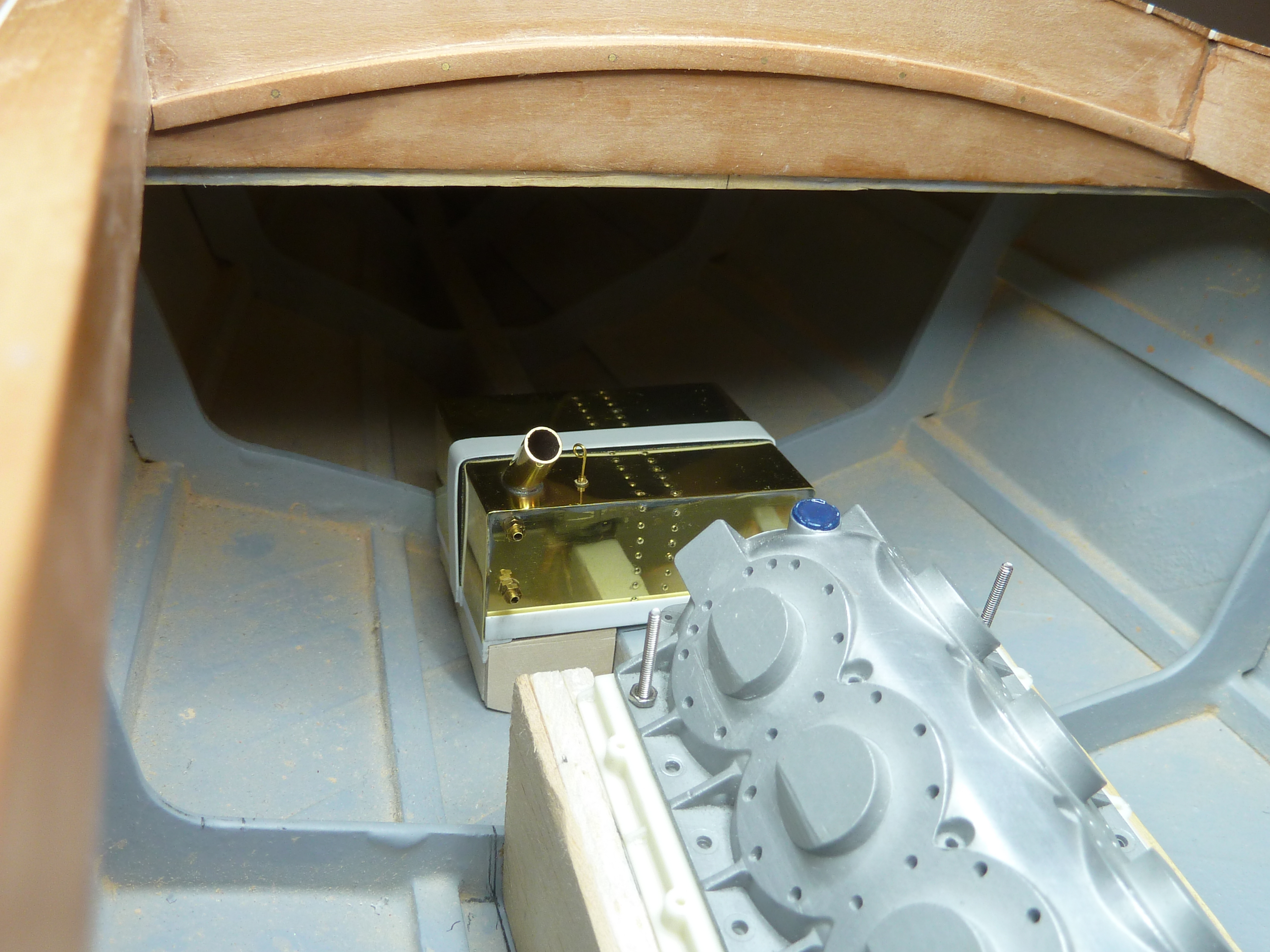
A small frame was made from plasticard to support the tank.
The new oil tank in its intended location toward the bows.
The filler cap was left off while I waited for some suitable sized brass tube to be delivered. Once that had arrived a simple cap was soldered up.
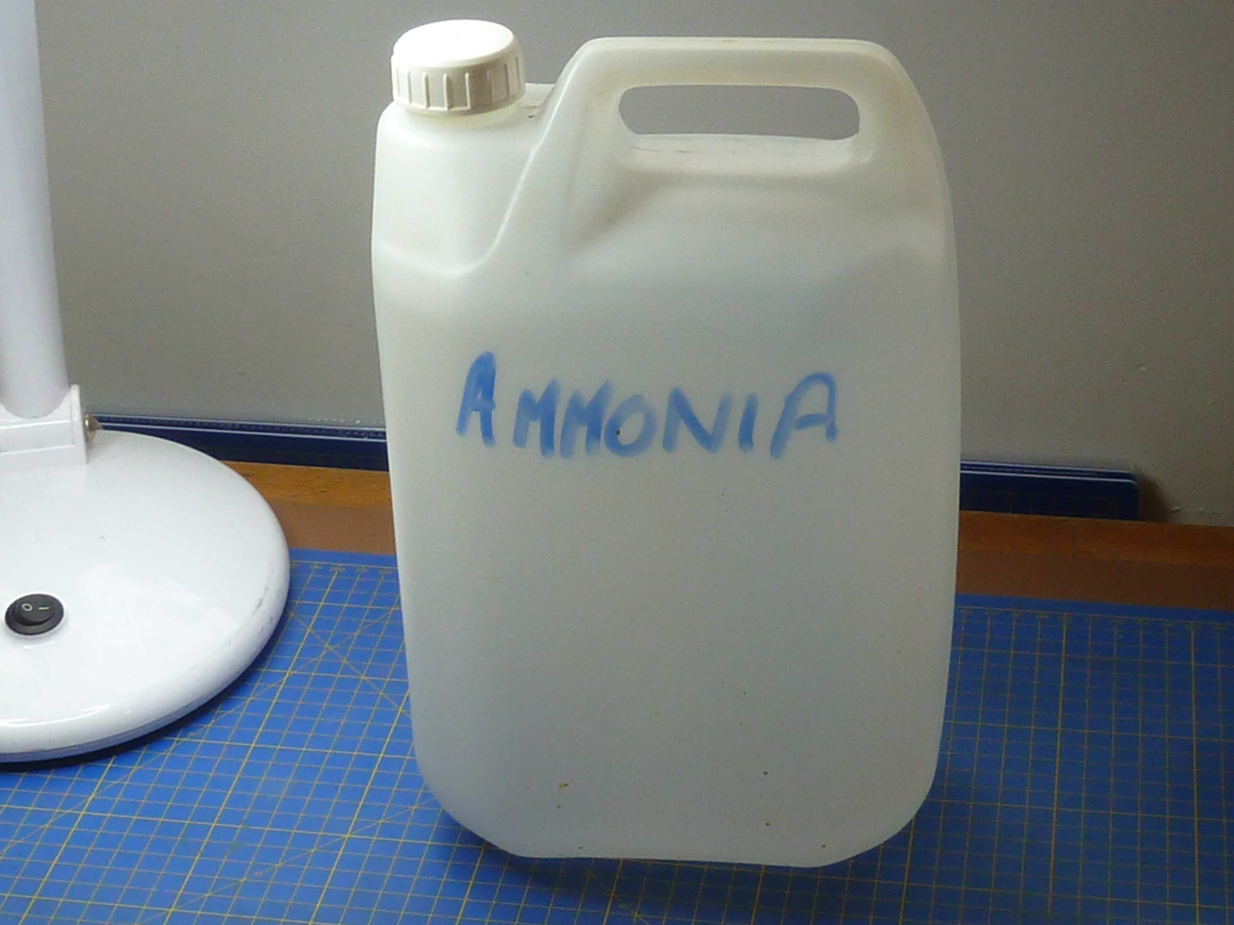
The whole affair was then ‘aged’ in another ammonia vapour bath. It was in there rather longer than I intended due to the distraction of our cat. Not a complete disaster though.
There’s not much room between it and the end of the engine. Fitting the oil pipes might be fun later.
That brings me on to the engine mount. Up to now I’ve been using a gash item made from balsa, because it’s easy to work. I wanted to turn that into something more substantial for the final model, so reached for the birch ply.
The inner parts of the mount will be completely hidden in the finished model so are more structural than scaled. It was quite an involved task to get the right shape, despite having built the balsa prototype. There was a lot of trial fitting and fettling before I got the shape I wanted. Particular attention was paid to getting the mount parallel to the main deck.
The whole affair was then given a quick coat of epoxy resin, and when that had cured, a sand smooth followed by a coat of matt light grey to match the rest of the bay.
The cockpit bulkhead in the engine bay was a bit of a mess as a result of hacking it about to make a hole for the gearbox to fit into. In order to restore order I’ve cut out some 1/64″ ply to act as a veneer and cover up the previous sins.
Having done that I wanted to make sure that it was actually possible to get the engine and gearbox combination into the bay while fitted to the engine mount. Trying to bolt the engine onto the mount once the latter is in the boat doesn’t bear thinking about.
The fit is exceptionally tight indeed, and requires more force than I’m strictly happy with to get it to snap into position, but it will go. Just. It amuses me to think that when I first set out designing the engine I was concerned it might look a bit lonely in the model’s engine bay.
As you can see from the picture above, having actually got the engine in place, I finished off the exhaust installation.
I’d always imagined that there would be a flexible section between the engine and hull mounted parts. When I was working as an aircraft designer I recall seeing a number of braided high temp pipes when vibration isolation and a degree of flexibility was required, so decided to try and replicate something similar. My design is based on some braided oil hose from a turbo installation left over from my kitcar building days.
While the hose might be flexible in real life it certainly didn’t want to go in the curves I wanted it to and was much too stiff for the model. The forces required to get it to lie ‘naturally’ were too much and something was going to break. In the end I resorted to putting in another supporting armature, made from 1/4″ copper brakepipe, to force it into the shape I wanted. The whole affair was then filled with epoxy resin, so it’s anything but flexible now.
As you can see from the above picture, I’ve also made some top-hat ferrules to support the pipe at the cockpit bulkhead end. They are made from brass pipe and sheet, soldered together, then bright nickel plated. They are designed so that the flexible section isn’t hyper-critical on length too. I’ll have a little leeway at both ends when it comes to final assembly.
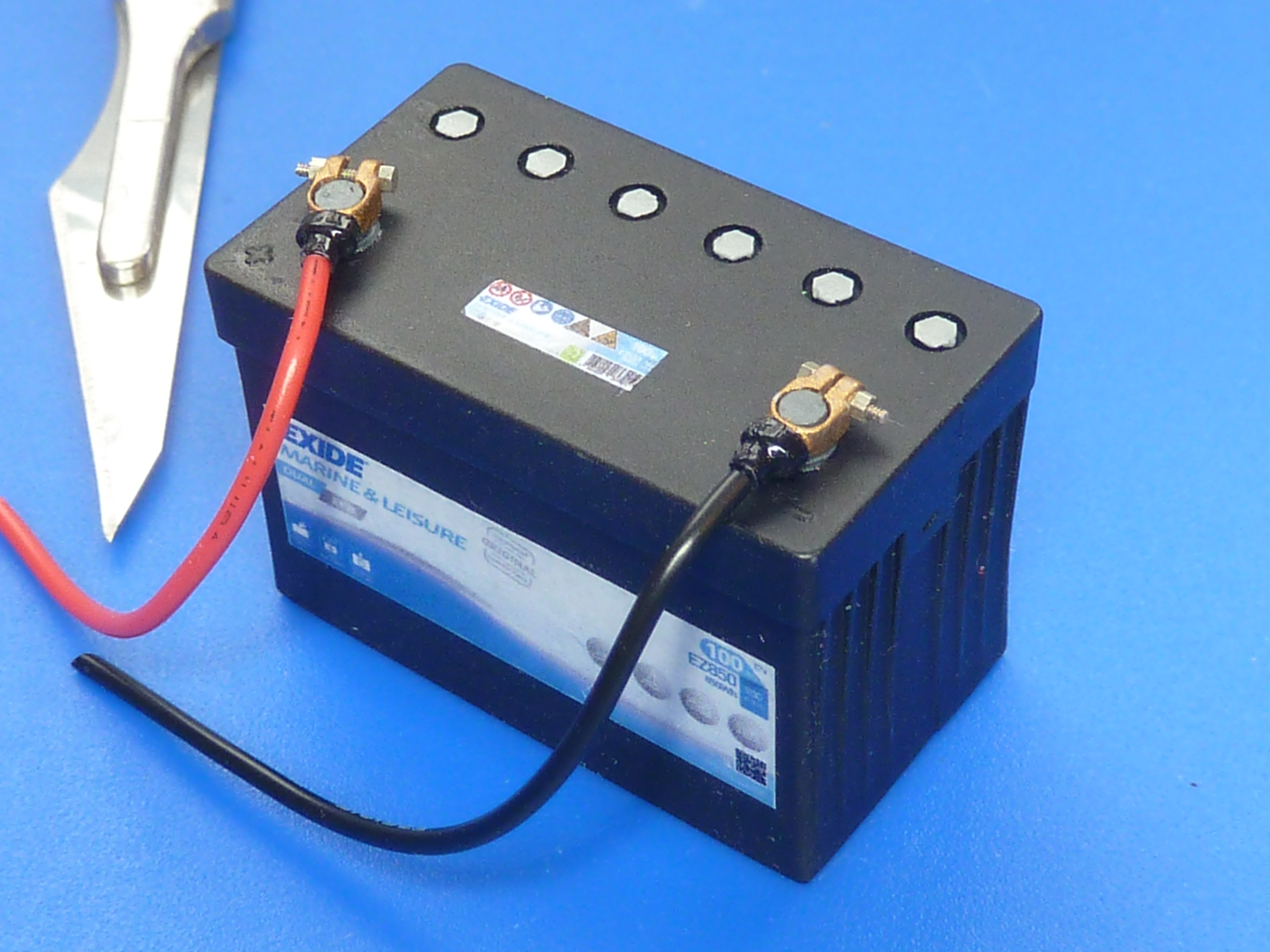
Next up was a battery.
I’m doing the model to look like a vintage machine might appear today. I’m already committed to that path actually, as the ignition wiring on the engine is modern style. No Gutta Percha insulation there.
Again I went down the 3D printing route because I’m much better at CAD than I am carving! A modern style battery was knocked up in CAD, printed, then used to make a mould for resin casting.
I also scoured the net for some pictures to make decals from. In this case an Exide marine battery of 100Ah capacity. I’ve gone for 12V too, as that is the norm for boats under 40′ apparently.
A quick coat of matt black followed by the decals and an overcoat of satin lacquer resulted in…
I had planned on a fairly detailed battery box for the engine bay, made from photoetched brass sheet, but some research revealed that most of them are simple wooden box affairs. Hence, that’s what I went for in the end.
The planned location for the battery box in the engine bay. The location is determined by the need to keep the positive feed to the starter motor as short as possible. That minimises the voltage drop along the cable during the very high current draw of engine cranking.
I’ve also finalised the installation of the main cooling water feed. In the picture some trial duckboards are installed, but they won’t make it into the final model.
The latest activities have been centred around making the engine bay door hinges and frames. I decided to photoetch them (as I did on the Chris Craft model) because that avoids any distortion of the thin brass sheet.
Masking up the brass sheet prior to etching. Both sides of the hinge are masked together. So at least if it is slightly out, both sides are out together.After etching and some fettling to sharpen up the edges and corners. The assembly at the rear shows two halves of the hinge inter leaved. Once the hinge pivot rod is placed in the base of the right angle the individual tabs can be bent around it to form the hinge.
Things aren’t going so well at the moment though, as the first hinge is malformed! One side must’ve moved in the jig during the bending of the tabs, so there is a distinct taper to one wing. If I can’t get it apart I’ll have to start from scratch again which is a couple of days work down the pan.
Yours,
Not happy of Worcestershire.
Yeah, where the sauce comes from. Lessons on how to pronounce it are available at reasonable rates…
Alternatively just say Wuss-ter-sheer.
Next month, how to pronounce Leominster, Gloucester and Shrewsbury.
I’ve finally got there. One post more than I thought I’d need, but the two engines are finally complete and a selection of photographs of them added to the galleries under the drop down menus at the top of the page.
There wasn’t much left to finish them really. The main activity required was the completion of the coolant hoses, and the installation of the exhaust studs.
As before the hoses were made up of three parts.
A wire core to make sure they keep the right shape during heating.
A polystyrene inner tube to give them the right diameter.
An outer sheath of black heat shrink tubing to give a true rubber appearance and thin wall thickness at the ends.
The black tube on the right of the picture is there to form the flared end on the coolant hoses, and is the same diameter as the lugs on the model. It was removed from the formed hose once the heat shrink tube had been shrunk to size.
Each hose was run to the model then measured up. A final version was then made from fresh materials, as I’ve found it is necessary to partially shrink the outer onto the assembly then bend it to shape. Once that’s complete you can remove any wrinkles in the outer by completing the shrinking operation. If you try to slide the heat shrink over a bent inner, like the one in the picture below, the inner wall of the curve wrinkles to an extent that can’t be remove entirely during the heat shrinking process.
Running a dummy hose to the model prior to making the final version.
The process is a bit laborious to be honest and caused me quite a bit of grief. In hindsight it would’ve been a much simpler option if I’d done it in conjunction with fitting the exhausts rather than after. As it was some choice epithets might have been uttered during the operation.
The hoses on the burgundy engine were by far the worst to do as the arrangement is more complex than on the black one because of the location of the water pump.
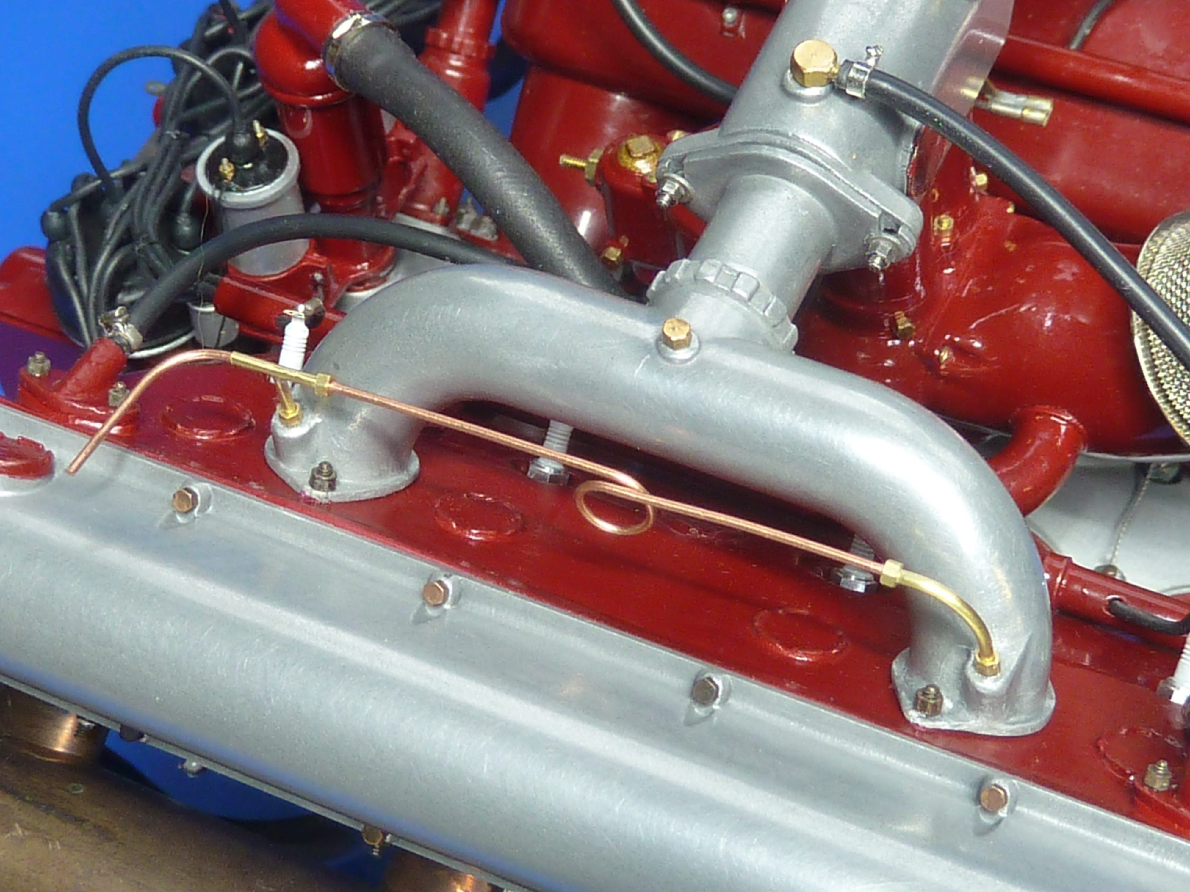
Other minor work included fitting the cylinder priming pipework on the top of the burgundy engine. For some reason this was quite difficult, which was a surprise as it was relatively straightforward on the black one and they are supposedly identical. Probably just an off day at the modelling desk.
The unfinished left hand end on the priming pipework will be completed once the engine is installed in the ‘Miss Severn’ model.
The coolant hoses also required the making of several batches of faux jubilee clips. These are fairly simple but take time. An appropriately sized tube is cut into thin sections and some thin (0.8mm OD) tube soldered to the rim. The whole assemble is bright nickel plated. As a final flourish a brass pin which has had its head slotted and then been bright nickel plated is glued into the cross tube to look like the screw mechanism.
The very last operation was to add the exhaust mounting studs. These are just glued on and have no physical function. They were made from Some M1 threaded rod with M1.0 brass nuts glued in place. The whole affair was then burnished to make them dark. Tedious and unexciting work. 32 required per engine.
If I were make another of these models I’d approach the exhausts in quite a different way I think. I’d keep the flanges separate from the exhausts themselves, which I have seen on some engines. That would make getting everything aligned much, much easier and would allow the studs to be actually glued into the block.
That’s it for these engines then. A lot of fun to make, but much more involved than I thought it would be. I’d secretly envisaged it taking about half the time it has. I wasted a lot of time and effort though trying to master white metal casting of the aluminium parts before admitting defeat and using the cold casting technique. Now that I know what I’m doing and have all of the moulds to hand I think I could build another engine in 250 – 300 hours. I might even do that as I’d like to have an unmodified aviation version too. They’re not cheap though when you add up the costs of all the nuts and bolts.
Here are some pictures of the finished models. There are a few more in the gallery pages too.
There is a CAD version of the aviation engine ready to go. I just need to get the exhausts printed off…
Aircraft version on the engine in CAD, which might get built one day.
Aircraft version on the engine in CAD, which might get built one day.
I had hoped that this would be the last post on the building of these engines, but they will not lie down and give in. The exhausts in particular have been giving me grief.
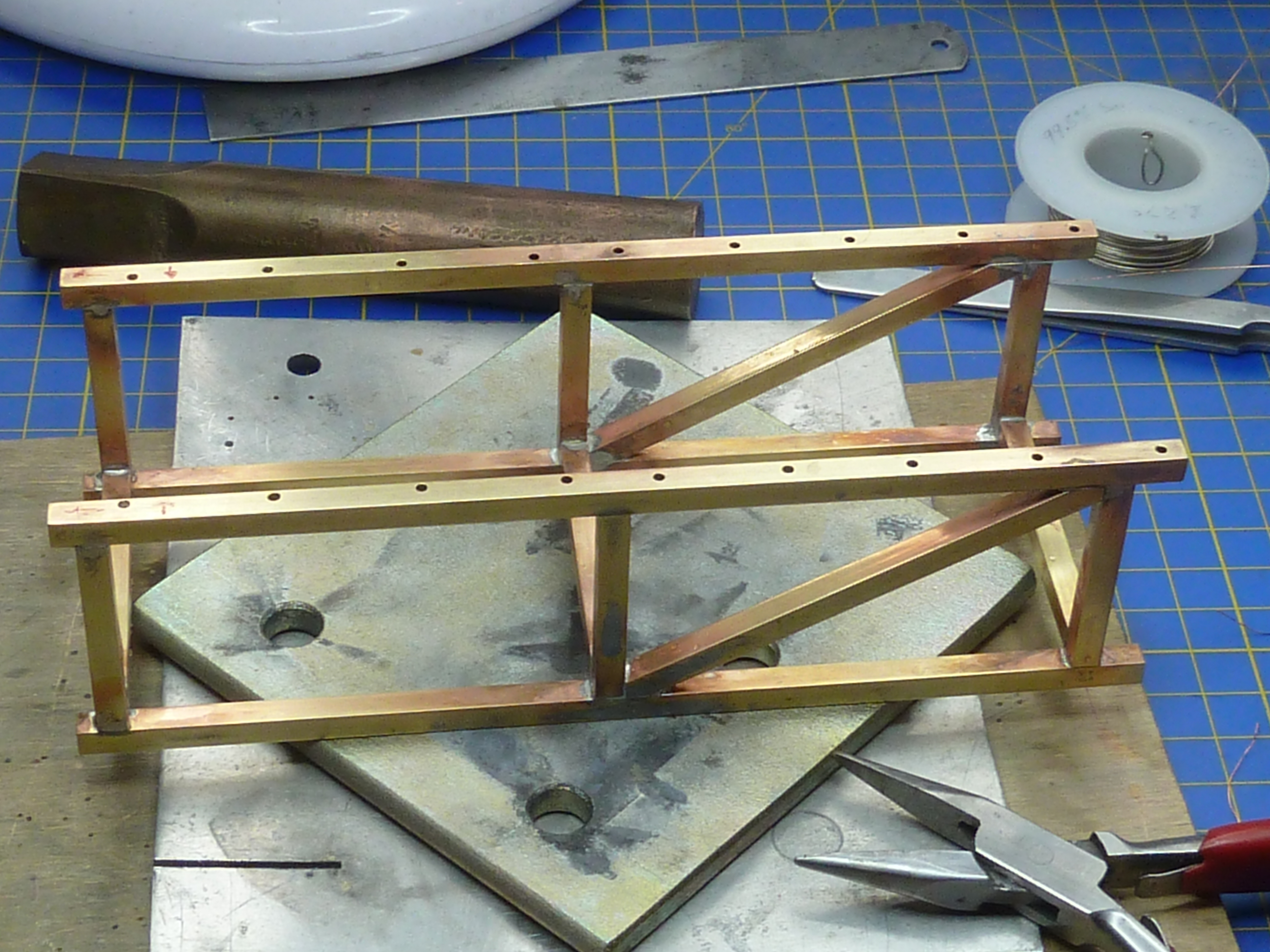
Given how large they are, and the visual impact of that, I wanted them to have a real metal feel to them. I didn’t think I’d be able to achieve that with painting, and hence decided to build them out of copper and brass (see previous post). They’ve turned out to be some of the most complex soldered items I’ve ever made, but I got there in the end.
Below are the basic items for the burgundy engine which will be going in the Miss Severn type model. They are complete and copper plated, but do not have the inlet and outlet water cooling pipes fitted.
I’m aware that a lot of my pictures show things after they’ve been cleaned up, so here is a picture of one of the exhausts during assembly.
And after clean up, but before plating.
I wanted to plate them to give a homogenous copper look. I have seen welded copper exhausts on one restored boat from this era so, if designed correctly, they must be able to withstand the heat. I doubt brass ever would though, so my headers needed hiding under copper plate. For the doubters, remember they are bolted to an aluminium casting so if your heat management is right, they must be able to work. Aluminium melts about 400°C (750°F) before copper after all.
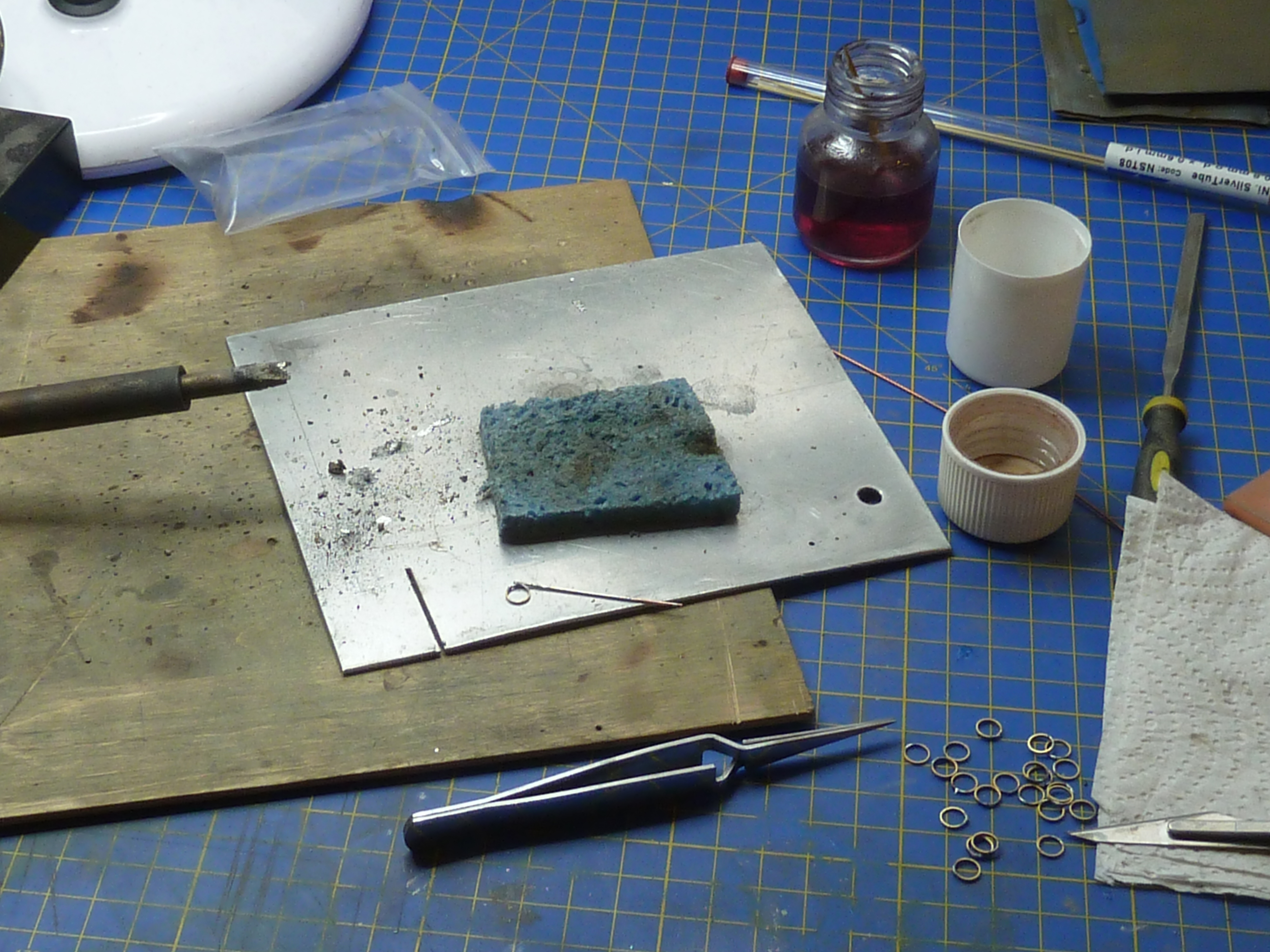
After plating with copper I wanted to give them an aged rather than a new polished look. I hit YouTube and tried a number of techniques found there.
I don’t know why, possibly because of the ‘brighteners’ in the copper plating solution, but Sodium Bicarbonate had zero impact. I even left the samples on a radiator overnight in a jar with bicarb solution in the bottom, but they were all still lovely and shiny the morning after. Acetic and citric acids were also tested (OK, vinegar and lemon juice to you) but didn’t really deliver. Immersion in an ammonia solution was exactly the opposite and just way too much. Verdigris all over the place in a very short time. Using burnishing solution worked quite nicely, but gave a blue/black patina, not the brown I was after.
Copper pipe naturally aged by leaving it, lonely and unloved, in my garage for 25 years vs the one on the right ‘aged’ in burnishing fluid.
In the end I found hanging the copper items in an ammonia vapour bath was the best option. You need to make absolutely sure you don’t get any of the neat ammonia solution on the samples though, as that leads to verdigris spots.
That all sounds quite technical and posh, but the reality was a 5L plastic can with a cup full of ammonia solution (34% by vol) in the bottom. The parts were hung off the rim on wires with the top popped back on to limit evaporation. I left the parts in there for about 2 hours, but the temperature in my garage was about 5°C (41°F) at the time. I doubt they’d need that long in summer.
Having proved the method on some samples, I put the black engine’s exhausts in to treat them. It was a disaster… I’m not sure what happened, but the copper plate started to flake off all over when I removed them. Something must’ve contaminated the surface prior to plating, but I’ve no real idea what. Perhaps my acetone had something in it or the cleaning brush did.
Ho hum…
Whatever, I had an enjoyable afternoon removing all of the copper plate and cleaning up to start again from scratch. Thankfully that went without any further problems.
The burgundy engine has a slightly different and more complex cooling arrangement to the black one, primarily because of the alternative ‘distributor’ rear end arrangement. That required some pipes to feed the water jacket from the pump.
I tried making them from tube, but couldn’t get the tight radius bends I wanted without the tube collapsing. In the end I made them out of solid 4mm rod. Say nothing and no one will know!
Water jacket feed pipes.
Some before and after pictures of the soldering ops.
Risky stuff, as I only used one type of solder, so there was a very real risk of unsoldering old parts while I was adding the new ones.
(I mainly use a cook’s blowtorch for my soldering).
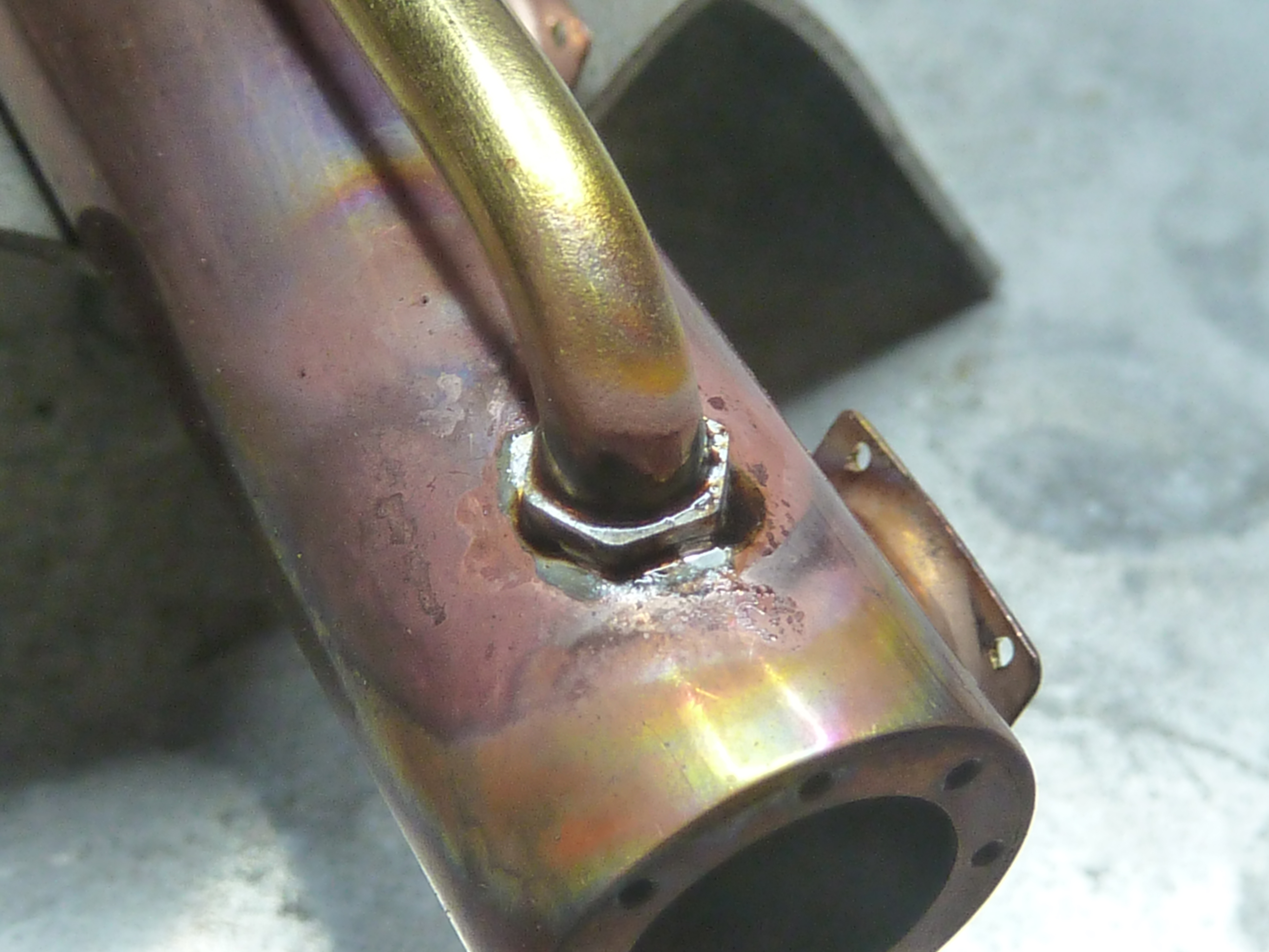
The end result after clean up and a couple of hours in the ammonia vapour bath. The steel spigots are there to mount the exhaust to the engine. The ‘mounting’ bolts will just be for show. The small water outlet at this end of the picture is actually a cold cast bronze part. I thought trying to solder a copper part on there was just pushing my luck too far.
And finally fitted to the engine.
I just need to finish off the rubber hoses to complete the build. They will be similar to those on the black engine.
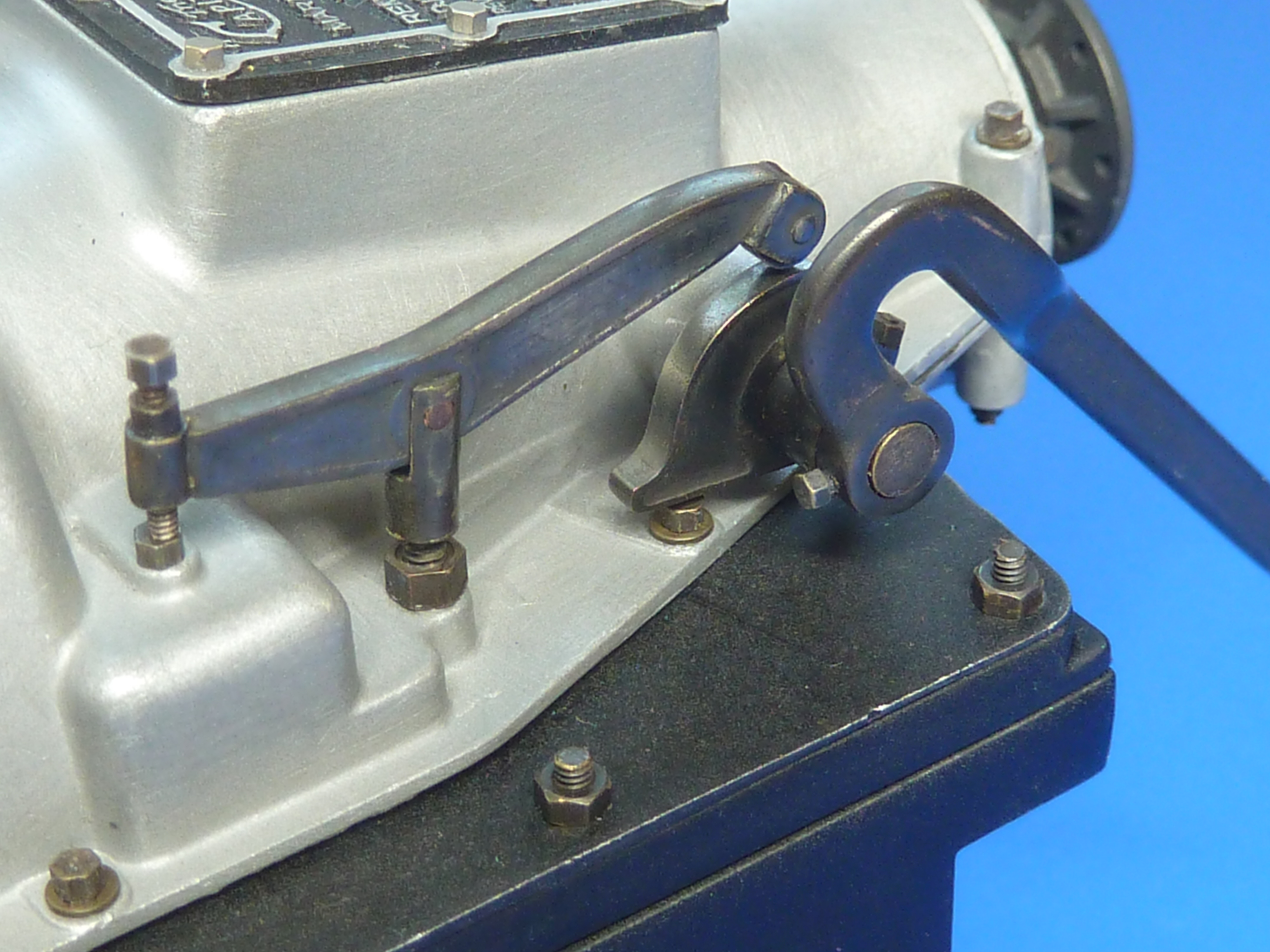
In addition to the exhausts I’ve also got around to finishing off the clutch. I call it that because I can’t think what else it would be, but I’m not actually certain of it. The thing has a massive mechanical advantage built in to it though, and it’s the only mechanism I can think of that would require that.
If you recall from my previous post I’d designed it in CAD and was intending to build it from photoetched parts.
The first version looked a bit weedy compared to the pics of the real thing, but did at least serve to prove the concept.
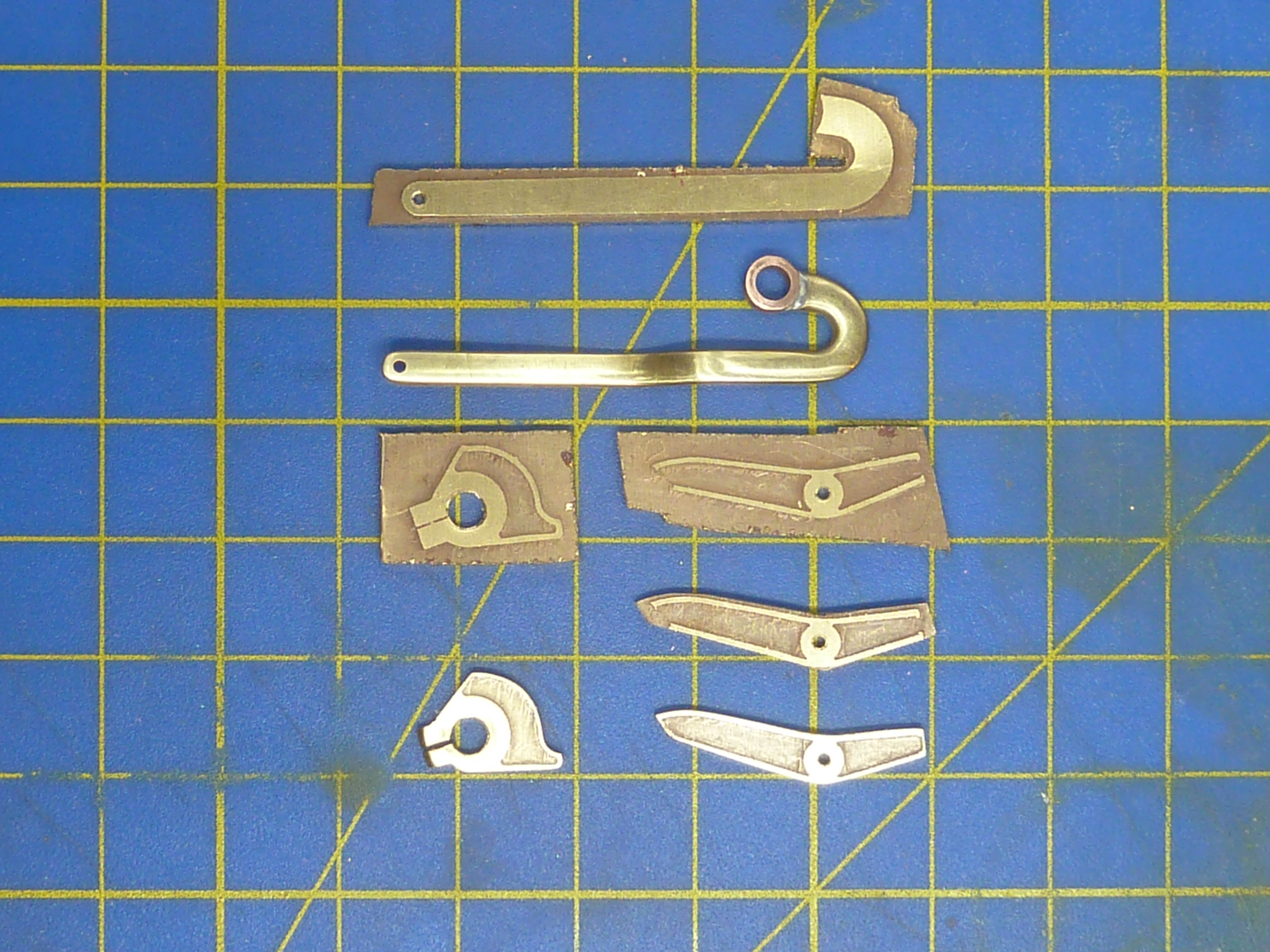
Clutch made from 0.9mm brass sheet.
The parts were eventually made from etched 1.5mm brass sheet.
The parts in various states of completion.
After burnishing they were installed on both engines. The thicker section looks much more in scale.
Final version of the clutch release mechanism. The lever turns the rising cam which in turn lifts the central pillar. The bolt on the left hand end provides and adjustable pivot point.
Another area that was finally completed was the carburettor controls on the burgundy engine. The black engine’s controls are much simpler as they don’t have to connect to anything and can be left as they were on an ‘as delivered’ engine.
However, as the burgundy one is going in the boat it does needs connections that can properly link to the cockpit controls. To that end I built a small brass confection out of sheet and tube to simulate some sort of Bowden cable arrangement.
I just need to run some thing black wires into the tubes once it’s installed in the boat.
I’ve finally got around to adding a maker’s nameplate to the burgundy engine too.
As the black engine will be a stand alone model in a little glass case I’ve made some name plates to go with it. They are the usual etched brass affairs, and are replicas of the plates actually fitted on the model. In fact the etch masks were made using the same print files scaled up.
Etched, filed and drilled.
Stained and lacquered.
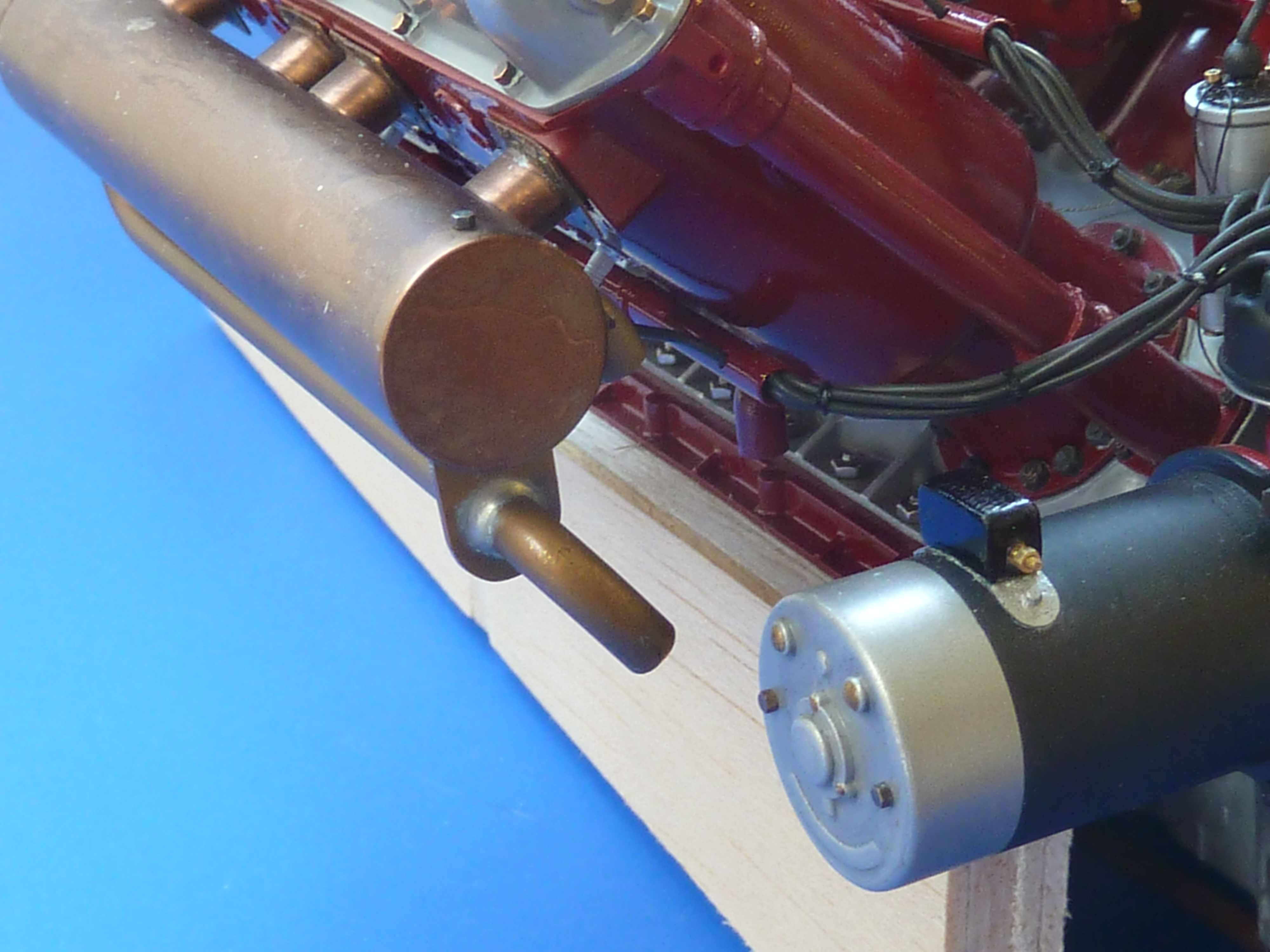
Having installed the exhausts on the burgundy engine it was possible to start test fitting the thing in the Miss Severn model. I’d already checked the fit with my rough and ready 3D printed space model, but it was still a bit of a relief to find it went in without any problems.
I can now start to plan the layout of the engine bay. One of the main features of this will be the exhaust run to connect up with the kit’s in the cockpit. That requires some form of flexible coupling and I’m intending to use some braided oil pipe that I have to hand. A rough mock up of the what is planned is shown below and is based on some of the high temp piping that I have seen installed in aircraft.
Further updates on the engine bay fitting and equipping will appear a under the ‘Miss Severn’ series on this blog.
There will be one more engine one though, to complete the black engine’s build log.
Well hopefully this will be one of the last posts on these engines and I’ll soon be able to get back to completing the Miss Severn and Chris Craft models. The engine diversion has been much longer than I anticipated and I’ve had to remind myself a few times that the actual aim is to build the boat model, of which the engine is only a part.
If you recall from my previous post, I was messing about with cooling pipes as the size I had intended to fit looked too large on the model.
I spent most of a day rifling through my odds and ends boxes trying to find something that would do the job. Attempting to satisfy the need for a thin wall thickness and small diameter was not easy, especially as some of the pipes have to go in quite tight curves. Thin wall and tight curves equals collapsed pipe. I’d also already had problems with the pipes fitted to the black engine putting too much strain on the mounting points and pulling them off, so whatever the solution was it had to also be low stress.
Hence, I really needed the pipes to be pre-formed to shape as well.
After a day of testing various ideas I gradually homed in on a compound solution. The pipe run was formed from some polystyrene tube with a copper wire core.
White polystyrene tube with a copper core was used to form the pipes to the required shape. Then black heatshrink was slipped over the formed pipe. The copper stops it changing shape under the heat gun, and the black tube on the right allows a flared end to be formed in the heatshrink. Heatshrink without adhesive means the latter tube can easily be removed when everything has cooled.
Heating the whole affair allowed me to bend it to the desired shape, and the copper core made sure it held that shape as it cooled. It also meant there was no chance of the tube collapsing in tight bends.
Once formed black heatshrink was slipped over the whole assembly and shrunk on with a heat gun. To allow the pipe to mate to the parts already on the engine I placed another, slightly larger, tube over the end of the copper core to give me a slightly flared end. That was then removed. Obviously you need to use heatshrink without glue for this process.
Below is a picture of the first pipe made this way. It is actually the crankcase vent connection to the carb inlet rather than part of the cooling system.
I’ve also made a proof of concept prototype of the cooling outlet into the exhausts (the cooling system is a total loss/open loop design as are most boats, and the water is dumped overboard using the exhausts). I won’t be able to finalise that part of the design until the exhausts are fitted.
Having finally resolved the piping conundrum I could get down to making all of the jubilee clips I’d need. They are just some 0.8mm copper tube soldered to a thin ring cut from brass tube.
The assembly is then cleaned and bright nickel plated, and as a final flourish, a slotted 0.6mm panel pin is glued in the cross tube to simulate the adjustment screw.
After a couple of days work I found myself in possession of…
Which doesn’t look much for the effort required. Ho-hum… onward and upward.
As a quick side activity while various parts were electrocleaning or plating, I made some more of the ID plates for the engine. One for the side of the sump and one for the carb. These were made as before: a custom decal applied to brass or aluminium sheet.
There is another ‘Simplex’ label I’ve seen mounted at the back of the sump, but I’m not sure it was fitted when the ‘Hispano-Suiza Licence Built’ was fitted on the side, so I haven’t added that (yet). More research needed.
As the burgundy engine had now reached the stage where it needed to be mated with its gearbox on the subframe I needed a second build stand that would take that whole assembly. Rather than build another gash one out of plastic I decided to swipe the one holding the black engine as that was already a bit battered from constant handling.
As the black engine was not far from completion I decided to transfer that to its final presentation stand which was made out of square section brass tube.
There’s £15s worth of brass tube in that little stand. £15!
The stand was painted with an etch primer, then finished in satin black from a rattle can.
Fitting the correct mounting bolts for the engine was a barrel of laughs. They are really quite hard to get at. The first one (of 14) took 45 minutes. Oh, deep joy…
Things did speed up quite a bit after I fashioned a few wooden wedges to hold bolts in place while nuts were fitted, but the job did severely test my patience. It really needs three 1/8th scale hands, especially as you are desperately trying not to scratch the castings or nuts in the process.
Having got both engines mounted on their subframes I could move on to finishing the detailing of the gearboxes. Key to that was installing the starter motors. I had previously cold cast the parts in aluminium, but some parts were definitely brass judging from pictures, so I remade them in cold cast brass.
The parts were then fitted in place and the detailing nuts and boots added.
The burgundy engine’s gearbox has a cut-out at the rear to allow it to fit around the stuffing box already installed in Miss Severn. The rear of the gearbox will actually be hidden deep in the bowels of the model and the cut-out invisible.
Having sorted the piping problems and got both engines mated to their gearboxes I could move on to the exhausts. These were water cooled and appear to be specific to each installation. I’ve certainly never seen a ‘common’ design around.
The big difficulty with the exhausts was the oval header pipes. One of the distinctive differences between the Hispano-Suiza 8B engines in the SE5a, Spad etc. and the 8F is the change from nice, simple, easy to find circular pipe, to rocking-horsesque oval on the latter.
I did try just squeezing some round pipe in the vice, but found that gave me a race track shape rather than a true oval. In the end I decided to make some custom formers using my 3D printer. The PLA plastic it uses it quite tough and strong enough to form annealed thin wall brass tube.
I calculated the size of tube required to form the oval based on the assumption that they’d have common circumferences and it came out at 7.1mm diameter. So, 7mm diameter tube it was. A former design was quickly knocked up in CAD and printed. After a few trials revealed that the mathematically ideal solution wasn’t in real life, so the design was slightly tweaked and reprinted. Quick to type, but that all consumed another day’s work.
15mm copper pipe for the water jacket of the exhaust and 7mm brass tube cut to length for the oval headers. The Mk.II forming press is in the background.
Using the slightly undersized pipe to form the headers did mean that all the lovely mounting flanges that I’d photoetched previously were now a slack fit and needed to be remade. So a tweaked etch mask and more etching…
The basic exhausts prior to having the mounting flanges soldered on.
And somewhat to my surprise it all fitted.
One of the engine’s discarded test castings was used to check the fit of the exhausts as they were assembled.
Here is one of the exhausts mocked-up on the black engine.
The only remaining question is how to finish the exhausts. I’d always assumed they’d be nickel plated in some way. To that end I knocked up a test piece to gauge which looked best, the options being:
Bright nickel plated on a polished finish.
Bright nickel plated on a brushed finish.
Dull nickel plated on a polished finish.
Dull nickel plated on a brushed finish.
The bright nickel on brushed looked awful and was right out. The ‘chrome’ finish was OK, but not really in scale.
Bright nickel plate. The left half of the tube has a brushed finish and the right polished.
There wasn’t much to choose between the two dull finishes, though dull on brushed had the edge.
Dull nickel plate. Left half of the tube has a polished surface and the right brushed.
Having mocked-up up the exhausts on the engine, the natural copper finish was actually quite nice on it’s own, and I have seen at least one boat restoration from this era where welded copper exhausts were fitted. Cost was not mentioned!
It was suggested that an aged natural copper finish might look good, so I’ve decided to give that a go. If it doesn’t work out I can always just clean things up and nickel plate anyway. I’ll let you know next time…
I’ve also been musing over how to install the exhausts in the actual Miss Severn model. Not surprisingly the faux exhausts in the model don’t line up exactly with the engine’s, and a small translation section is required (the S-bend in the CAD rendering below).
Based on my aircraft experience I also assume that the exhaust system would have some sort of flexible anti-vibration part to isolate it from the hull and it seemed logical to combine the two.
At the moment I’m working on the idea of using some braided pipe to form the link piece. I’m not 100% convinced yet though as the braid is perhaps a little overscale.
The other main activity that is ongoing to finish the models concerns the clutch mechanism. I have very few pictures of this and there has been a lot of supposition going on in designing it (that it’s the clutch is supposition for what it’s worth). In fact it took me about an hour of staring at the few pictures I have to work out how the thing functioned at all. It’s one of those things where it’s blindingly obvious when you know what you are looking at, but quite opaque otherwise.
Whatever, the design is complete and just needs to be made. I’m not certain how I’ll do that yet, but photoetch is top of my list.
The clutch release mechanism in CAD.
One of the few pictures of the real thing that I’ve found. It’s of an engine that was auctioned by Mecum Auctions..
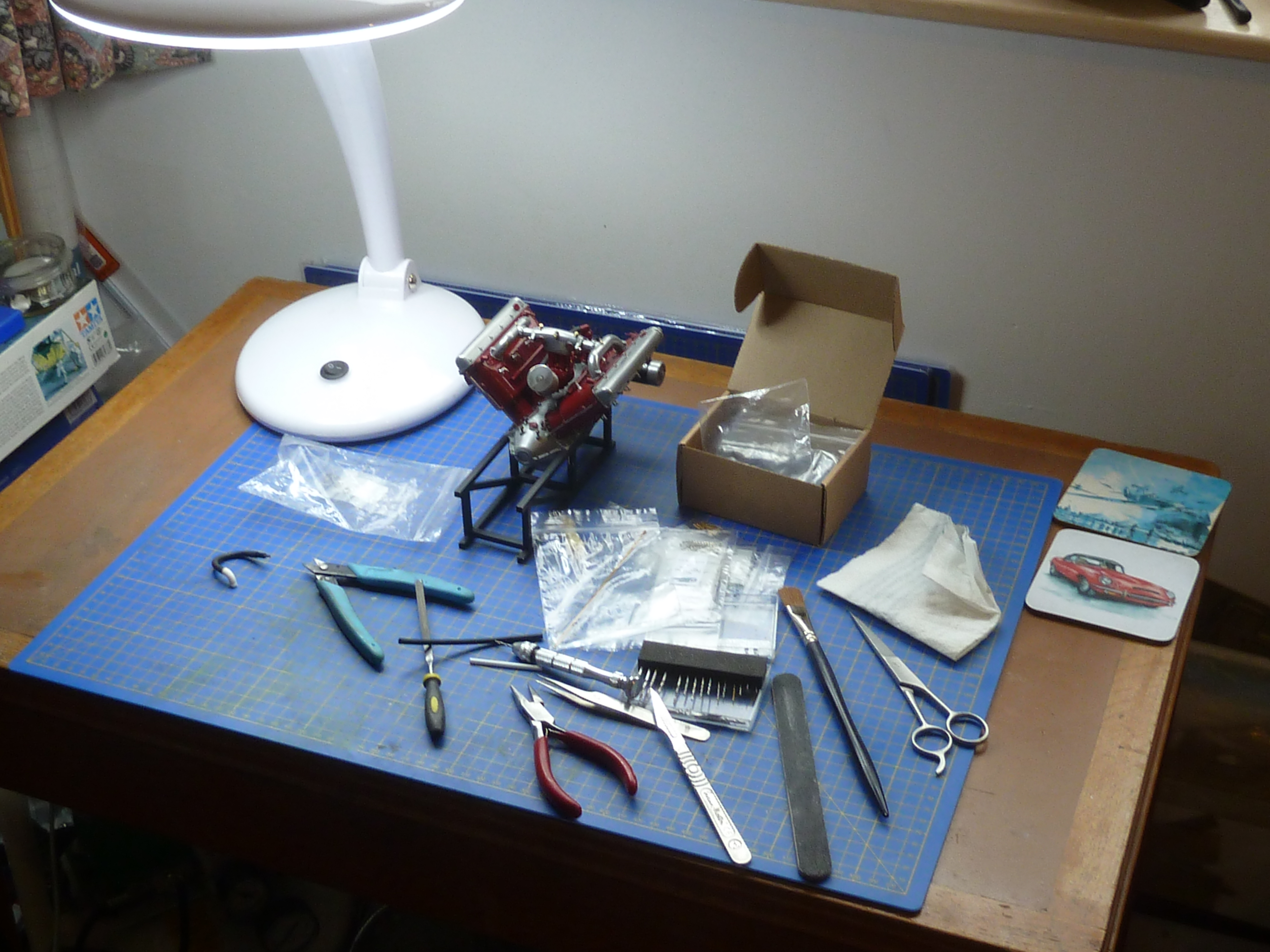
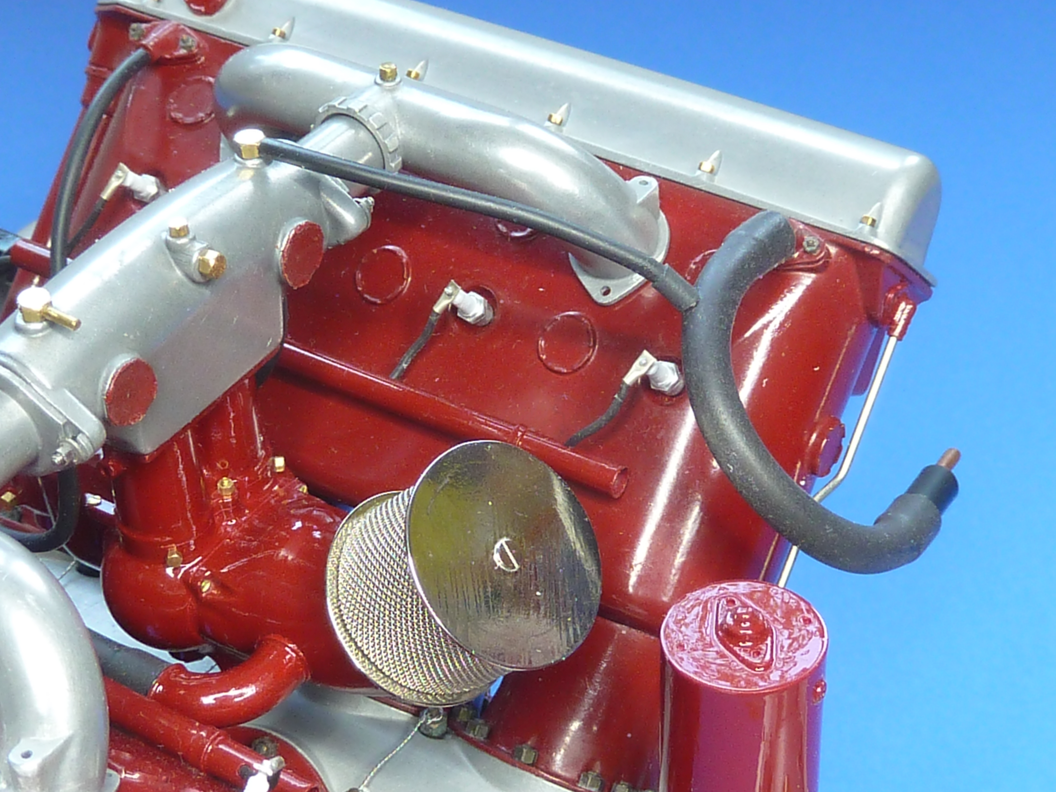
Here are a couple of pictures of the engine models as they stand at the moment.
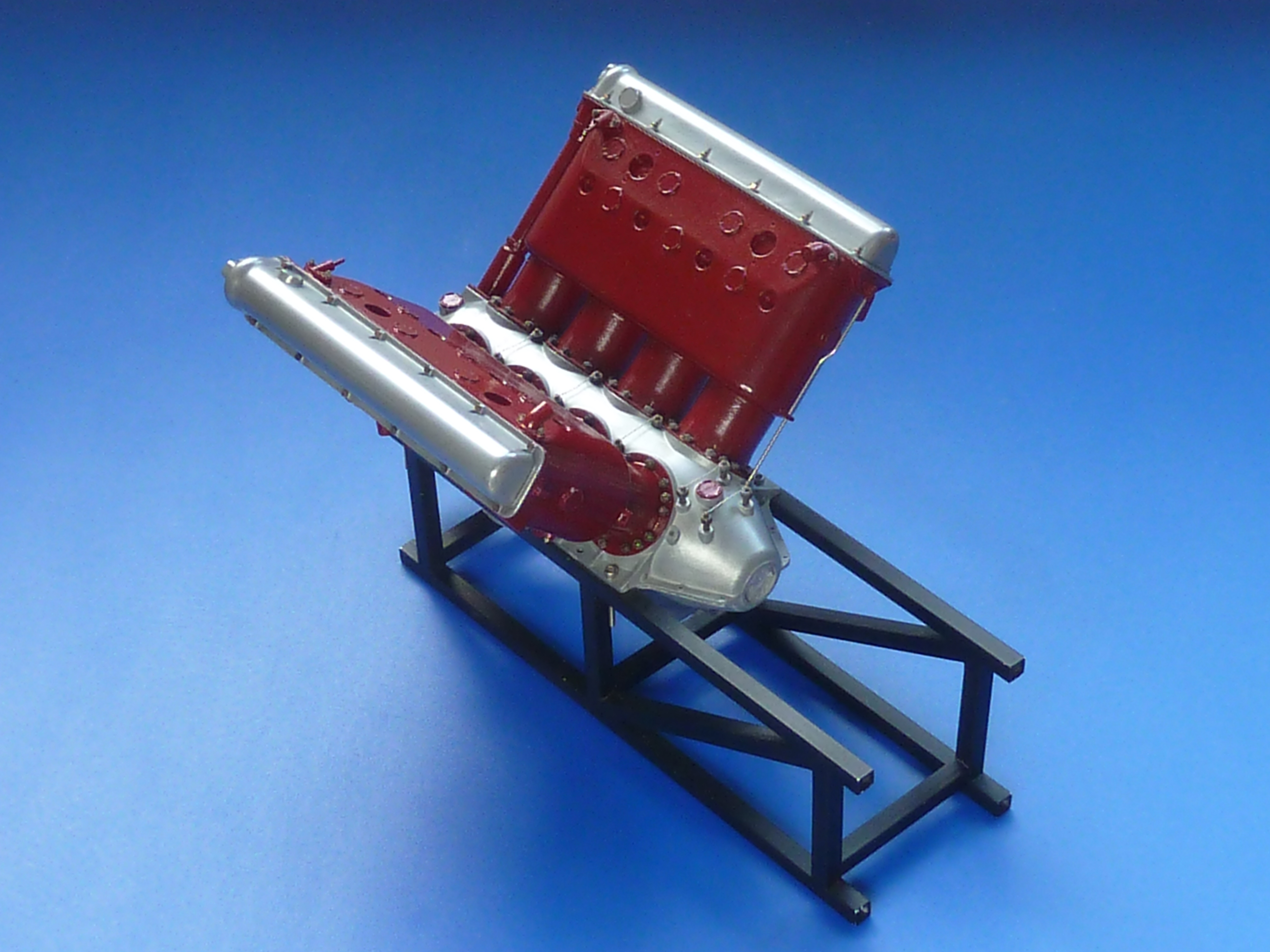
I’ve continued to push on with the two Hispano-Suiza engines, but the burgundy coloured one is going in a slightly different direction to the black.
After adding both cylinder banks to it was time to look at the induction manifold.
Previously it had been a single piece casting which worked quite well, especially in pewter. It was very awkward to remove the more delicate cold cast resin part from the mould though. The one installed on the black engine did suffer a little damage that had to be repaired. The arrangement also has no adjustment within it, so getting the cylinders exactly the same height and at 90° to each other becomes critical to a decent fit. I wanted something that was a little more tolerant of minor errors.
The obvious solution was to divide the casting up in to 5 parts, as it is on the real engine. You quickly appreciate that the original designers must’ve done this to allow for manufacturing tolerances, amongst other reasons.
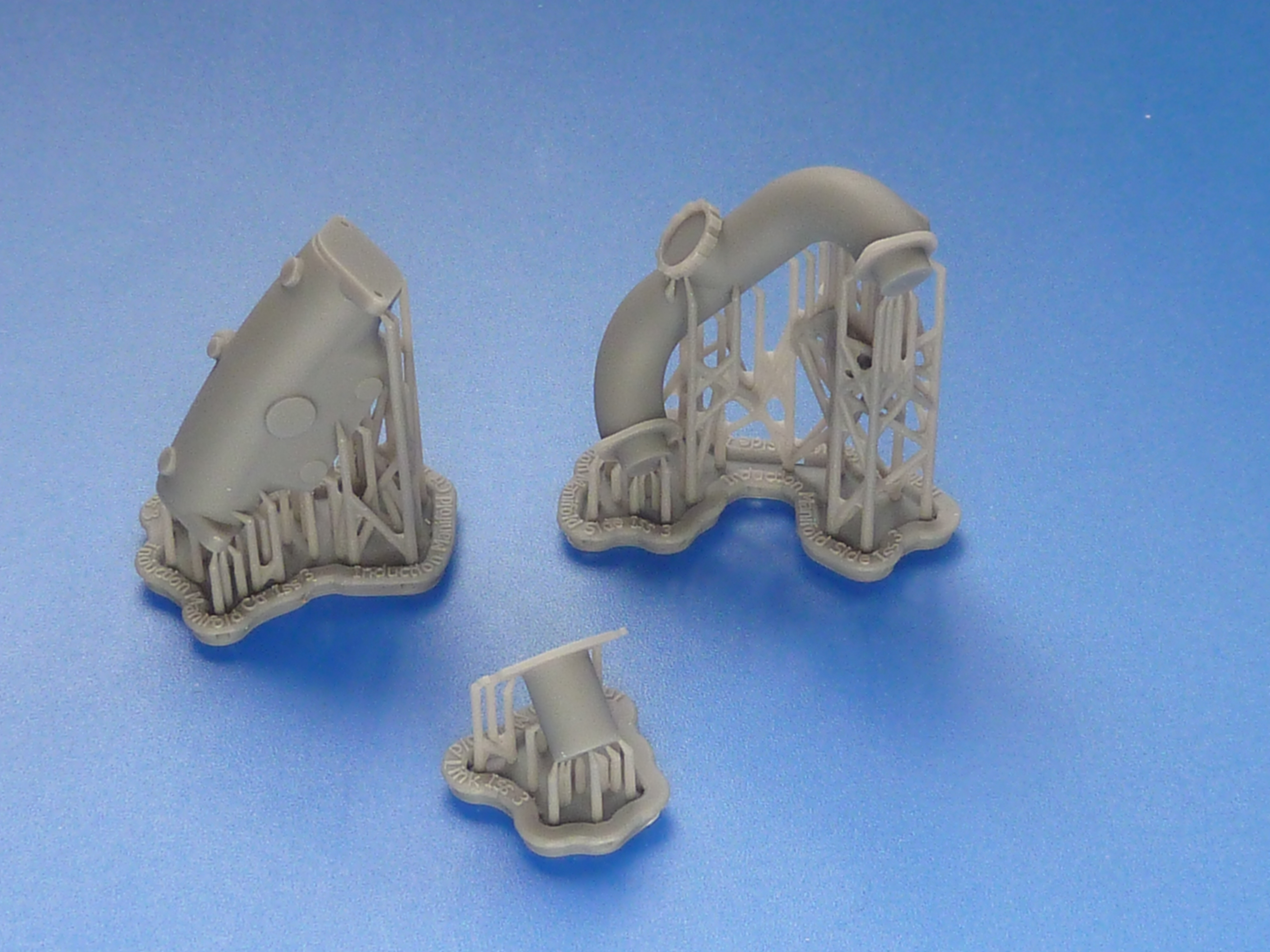
Hence a revised version was developed in CAD and sent off to be printed.
The revised parts fresh from the 3D print bureau with the print supports still attached.The parts after a quick clean up. The manifold is symmetrical about the centre, so I only need one side printing to make the mould for both.
The link piece in the centre of the picture above is deliberately slightly over length so that it can be trimmed to a perfect fit on the engine, giving me the slight adjustment I wanted.
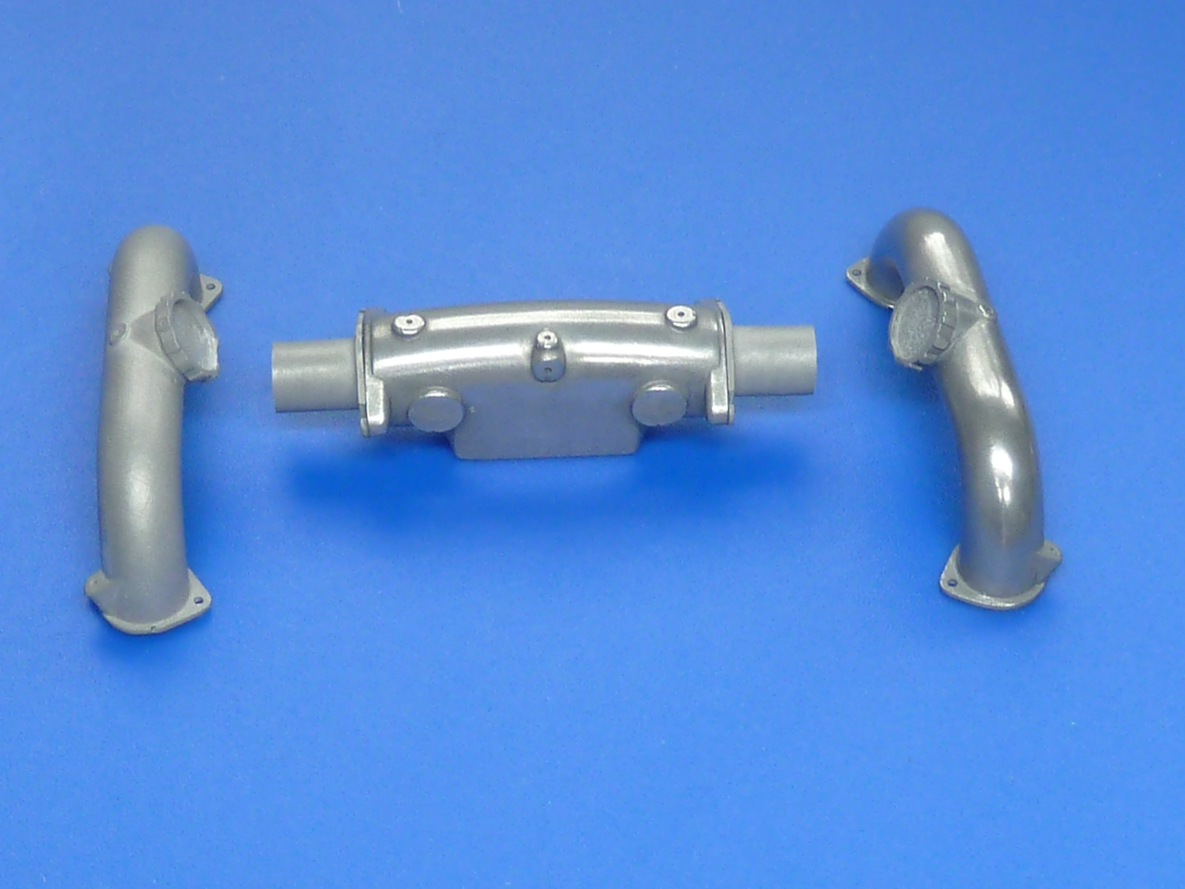
The cold cast components. The left hand part has yet to be polished.
The link pieces were glued to the central casting and the outer parts dry assembled on the engine using 1 mm bolts to locate them accurately. Then commenced the trial-fettle-trial sequence making sure I reduced each link piece equally in length. During the process I also filed off the locating pegs on the bases of the side pieces because they were more trouble than they were worth to be honest.
The result is shown below, and a it is definitely better fit than previously, though there’s no actual visual difference between the two arrangements.
The parts can’t be permanently fitted though until the carb has been attached as well as the plugs, ignition leads and their guide tubes in the V.
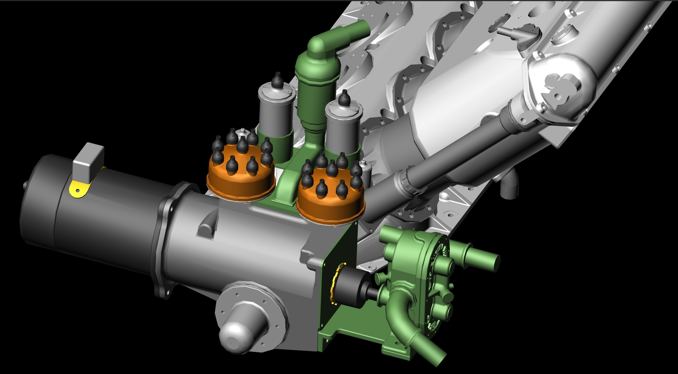
Speaking of ignition systems brings me on to the main change on this model. The black engine retains the magneto ignition system of the aircraft engine. The full Auto Engine Works marine conversion changed this to a coil/distributor version with dynamo. This makes more sense in a boat where swinging the prop is problematic to say the least, and a starter motor with charging system almost essential.
I wanted to model this arrangement on the burgundy engine, so it was back to CAD to develop…
Once again a set of .STL files were created and emailed to the 3D print bureau and 3 or 4 days later the printed parts arrived in the post.
STL = STereoLithographic which was the process used in the earliest 3D printers. The processes have changed, but the file type has stuck.
The parts with print support structure.And cleaned up ready to make moulds from.
Moulds were taken and the parts cast in polyurethane resin. The dynamo and front face of the water pump were cold cast because they would have bare ‘metal’ areas I wanted to highlight. Incidentally, exactly the same resin was used throughout. The only difference is that the cold cast items have 67%, by weight, aluminium powder added. The end housing was also cold cast simply because I had a little mixture left over after the other two, and it seemed a shame to waste it.
The parts cast in resin. The water pump has also been partially assembled in this picture and the bare metal part of the dynamo polished up.
The water pump faceplate came out quite well.
A quick bit of airbrushing later…
The black and silver components were sealed with a satin varnish.
The rest received a coat of burgundy gloss.
Once it had hardened I scraped back the faceplate of the water pump to highlight the company name.
The assembly also included a few photoetch components. The mask for them is shown on the right in the photo below. The large mask is for the exhaust system, including another drill template. I’ll come on to that saga in a future post.
The picture below shows it all assembled and mocked-up in-situ, but no plumbing or wiring has been installed yet. The pipe in the photo below is a trial fit, and I think it needs a smaller diameter one really. A bit inconvenient that, as the lugs are designed to take it. Guess which parts aren’t included in my CAD model…
The distributor assembly on the real engine includes a mechanical means of adjusting the timing advance. To replicate that it was back to CAD again. Then Photoshop to develop more etch masks. I cocked things up slightly on the latter. I forgot to add sprues to them and had to stop the etching process when it was 90% done and the components were still held together. Otherwise they would’ve fallen off the support and disappeared in to the bottom of the etch tank, never to be seen again.
Two sets of advance and retard mechanism components. The top are fresh from the etch tank. The bottom ones are after clean up.
After the residual flash had been removed the parts were stained and assembled using 0.7 mm brass pins as pivots.
I couldn’t resist mocking the whole thing up again on the rear of the model. It won’t be fitted permanently until I have sorted out the cooling pipe size issue and have installed the spark plugs etc. in the V of the engine, which will be the next job.
The advance and retard mechanism assembled and in place at the rear of the engine.
As an aside: I mentioned last month that I might put some mild weathering on one of the two engines, but wasn’t sure about the idea. To get an idea of how well it might work I carried out a trial on the scrap gearbox casting left over from when I dropped it.
Pre-weatheringPost weathering trial.
I’m reasonably happy with the result, but need to include a bit more gloss black in the mix to give a more oily appearance. Other than that I think it’s on.
It’s been decided that the black engine will be the standalone desk curio and the burgundy one will go in the Miss Severn boat model. Based on that it’s the black one which will get the weathering treatment.