Well, it’s been considerably longer since my last post than I’d hoped but I have made some progress on the Sopwith Camel in the interim, despite illness, and the model is looking good, even if I do say so myself.
As all of the rest of the wings are pretty much the same story as far as building them goes, I’ll cover them all under one post on here.
Next up was the lower port mainplane. The idea was that I could use it to prototype the changes I intended to make to the basic model, and if it didn’t go well they’d end up being covered up anyway as that is the side of the model which will be finished complete.
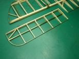
The changes centred around the wing tip and trailing edge, though some detailed bracketry within the wing was also modified. The picture below shows the wing made according to the kit’s instructions with a wooden wingtip and trailing edge.
For what it’s worth I used a thin super glue for wood throughout. The plan was to lightly stain and varnish the finished wings so any bleed from the thin glue would be hidden.
Below are a pair of photographs of the Shuttleworth Trust’s Camel (which is itself a post war replica), and a wing from a Rotec Engines new build replica, which shows the metal wingtip trailing edge that I wanted to reproduce.
To start with I fixed the full sized plans supplied with the kit to some plywood and covered them with some clingfilm to stop parts sticking to them.
Then came the somewhat tiresome task of pressing out all the components, cleaning them up and sanding them smooth before they were assembled as per the instructions (sort of).
One change I did make was to solder the strut mounts together rather than attempt to glue them or hold them together with the rigging pins.
Amother detail change involved the anchoring of the far ends of the bracing wires. In the kit these fix to standard lugs but metal tubes appear on the full size aircraft I’ve seen. The modified fixing is shown below with a picture of an original.
In addition to the modified fixing tube, you can also see my first attempt at making a simulated turnbuckle. As mentioned before, the kit uses simple lengths of copper tube in their place. This is OK for one end of the rigging wire, but the other should have a proper turnbuckle to allow the tension to be adjusted. They can be seen in the picture of the bare centre wing above.
While it looked OK, the little loop on the end was pretty difficult to make and didn’t sit well with how Hasegawa intended the rigging to be installed. In the end, for simplicity’s sake and my sanity (around a 100 of these things are required) I dropped the end loop and just threaded the cord straight through. The thread was then attached to the standard Hasegawa lug and the ‘turnbuckle’ pushed hard up against it and glued in position. The missing loop is obvious if you look for it, but the arrangement is OK from a distance and is better than the simple copper tube.
The metal wing tip and trailing edge were simply made from brass wire, suitably annealed and bent to shape over the plans. They were held in place with small strips made from brass sheet. These mimicked the fixing tabs on the real thing.
On the first, lower port wing, I used 1.5mm rod, but felt this looked too heavy so changed to 1.0mm for the top centre section and starboard wings.
The progressive changes can be seen in the picture below of the 3 types of aileron.

That pretty well completed the basic assembly of the wing structures.

Next up, painting and covering.


Great work !
Welcome “back” !
LikeLike
Thanks.
LikeLike
Welcome back. Your work is inspirational!
LikeLiked by 1 person