
Having shelved the Chris Craft build for the time being until I can locate some acceptable fittings, or am well enough to make my own, I decided to move on to another boat build.
The model chosen was another 1/8th scale model. This time of a 1922 Gold Cup race boat derived design called Miss Severn. The kit is produced by Mack Products, and mine included the add-on lighting set. As the model will be built for static display, none of the radio control elements will be fitted.
The original boat the model is based on was built to contest the 1922 Gold Cup race in the US and was called Arab VI. It was designed by John Hacker of the Hacker Boat Company who was an innovative designer that produced a number of very successful race boat designs between 1910 and 1939, despite having fragile health.
Arab VI was built to take advantage of the extensive Gold Cup rule changes introduced in 1922 to reduce speeds, costs, and also break the stranglehold that the designer Gar Wood had come to enjoy under the unlimited engine rules which had seen an influx of war surplus Liberty aeroengined designs of substantial power (900bhp).
Arab VI came second in the actual 1922 race, but recorded the fastest lap, ironically losing to a 185 bhp Packard Chris Craft piloted by Col. Jesse Vincent, the co-designer of the Liberty engine.
The boat never actually won the Gold Cup and was briefly fitted with a Hispano Suiza engine and then finally a Curtiss Conqueror V12 to race in the unlimited K class. In this latter guise, and renamed Miss Severn, it enjoyed considerable racing success.
The subject of the kit is the modern Miss Severn which was built from the original plans by Mark Mason in 1994. Rather than the Curtiss or Hispano Suiza engines, this incarnation of the design was fitted with a 650 bhp Rolls-Royce Meteor engine of 27 litres (1650 cu in) capacity. The Meteor engine is an unsupercharged version of the better known Rolls-Royce Merlin, and was adapted for use in a number of British tanks such as the Centurion before being adapted by privateers for marine use.
Work starts with laying out some guidelines on the assembly board to aid in the alignment of the frames.

The keel is then assembled flat from a number of laminated pieces. All the pieces in the kit are supplied laser cut and only require tiny tabs to be cut to release them from the carrier sheet. The laser cuts are extremely accurate ensuring minimal finishing is required and a good fit.
While the glue in the keel dried the batons to hold the cockpit floor and ceilings (sides to non-nautical types) were fixed to the appropriate bulkheads.


One thing I would point out is that on frame F7 (forward cockpit bulkhead) there are markings for two horizontal batons to be fitted (dotted oblong marks towards the bottom of the picture above) which aren’t mentioned in the instructions, but clearly appear later in the build. Fit them now.
The frames were then assembled dry to the keel and shearwaters. Once assembled, the keel is glued up in a sequence defined in the instructions. Getting them all in the right slot at the same time was a little frustrating. As soon as I got a few in, fitting another caused them to come loose, but we got there in the end.

Another word of warning on this. The instructions tell you to ensure that the frames are fully seated in their slots in the keel. This may be true for the forward ones, but not some of the mid section and aft ones. If you glue them fully home they’ll sit above rather than in contact with the base board, which is the correct position. There should be just enough of the keel proud of them to allow you to sand it true to the frame profiles and peak at the Centreline.
Once the keel is correctly glued in place it doesn’t take long to add the shearwaters, frame batons and chines. The shearwaters are assembled from two pieces of plywood joined with splice doubler. It might seem obvious, but when fitting them make sure that the doubler is on the underside of the deck when the boat is right way up. I know someone (cough) who didn’t follow this advice and it proved a bit of a sod removing the doublers when it came to planking the deck later.
At this stage in the build you can really see the beautiful lines of the Hacker design.

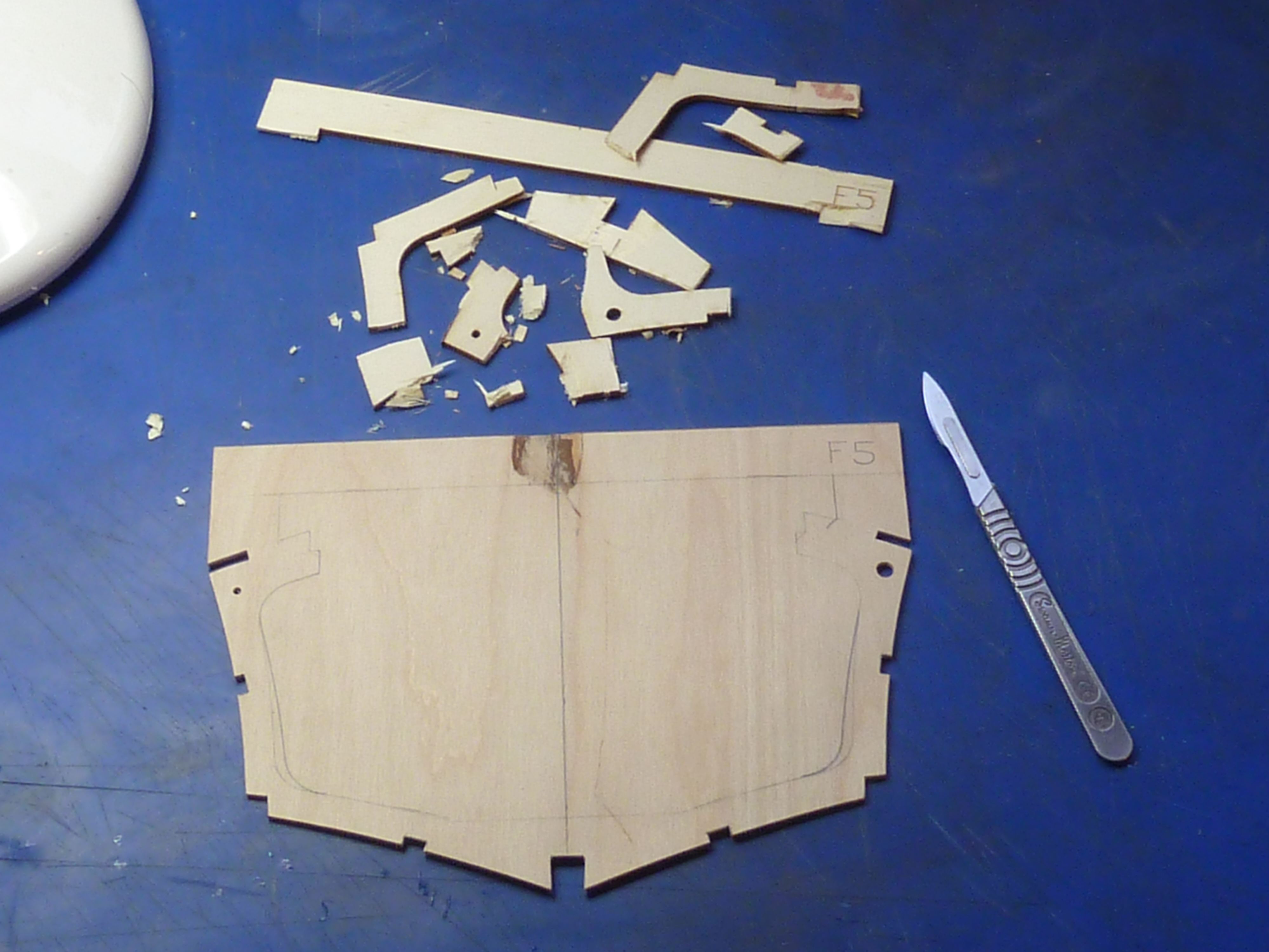
Or you would, if the kit had come with the correct frame F5.
Unfortunately due a configuration control problem a number of kits appear to have been produced with a rogue frame F5. It is manifestly too large when you come to fit the chines, to the point where the hull has a coke bottle shape around F6.
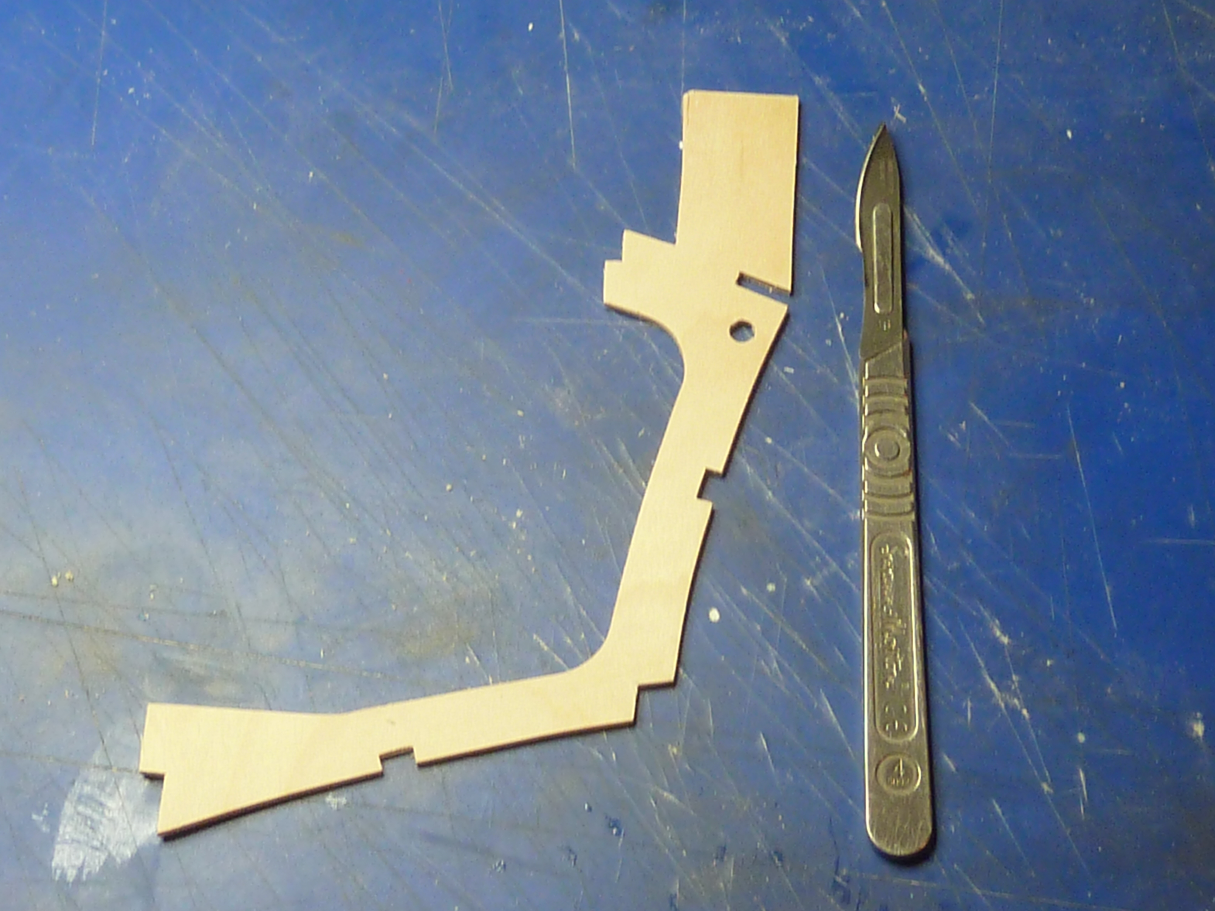
As up to this point the general fit of items had been excellent I assumed I’d cocked it up somewhere and went about trying to retrieve the situation with shim pieces etc, but to no avail. Eventually I emailed Rich at Mack Models who confirmed it was a known problem, and emailed me a PDF of the corrected F5 which I cut from some plywood stock I had.
Removing the errant F5 was relatively easy though I completely destroyed it in the process.
Inserting the new frame into the assembled hull wasn’t too difficult either, though I did have to split it at the keel.
Having done so the proper lines of Miss Severn were restored.

While I can’t fault the responsiveness of Mack Products when I advised Rich of the problem, I would’ve preferred not to have needed to draw on it at all. A pre-delivey check or an erratum sheet included in the box would’ve saved me some grief. I would stress though that the positives of making this model have far outweighed the negatives so far and I’d happily recommend it to others, but with a warning.
In the brief period that I was waiting for Rich to get back to me I carried on with the assembly of the transom. I’m still not 100% certain I’ve got this bit right if I’m honest.
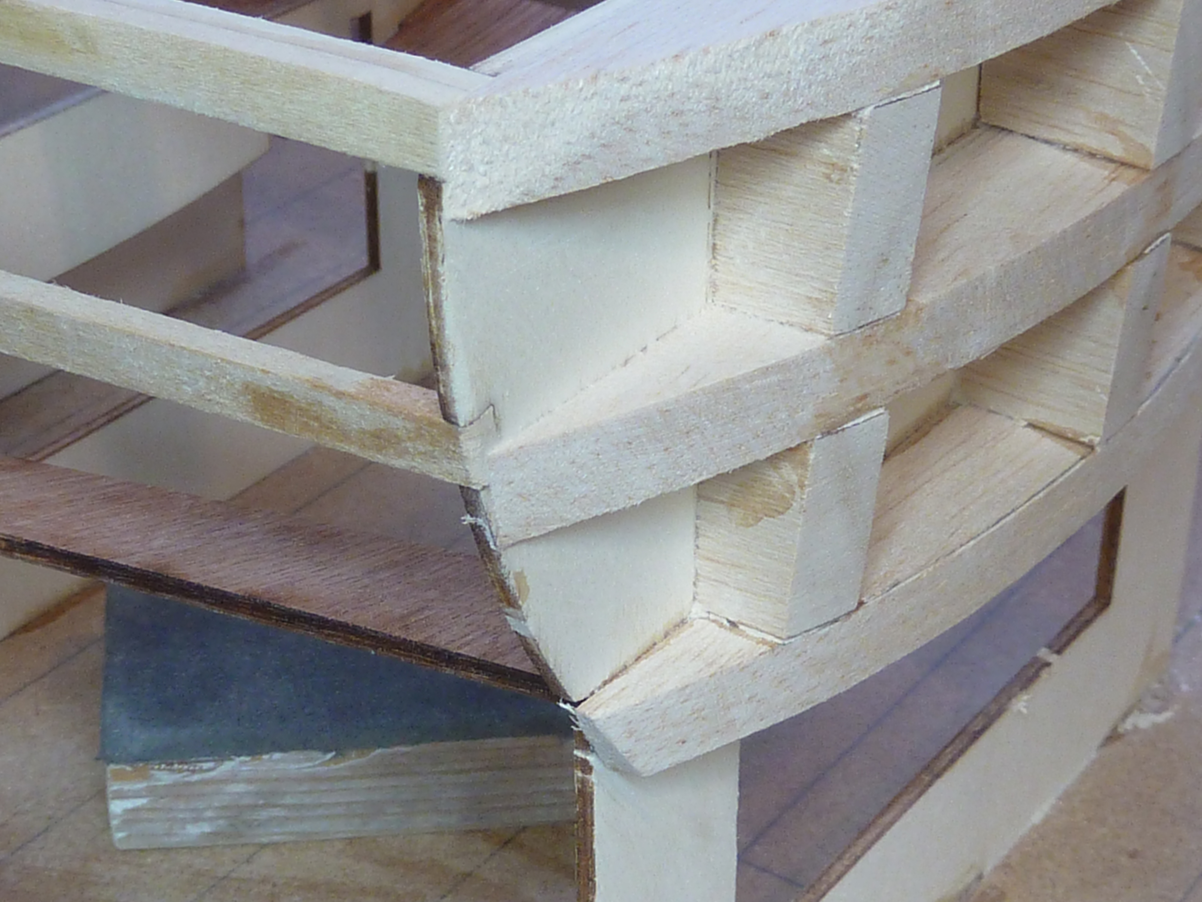
The kit comes with preshaped balsa blocks to ensure you get the right curvature. However, if you fit them exactly as is, it means the sternmost ends of the side sub-planking will increasingly finish in fresh air as you move up from the chine. If you shape the ends of the balsa pieces to avoid this and finish flush with frame F11, the transom ends up in a compound curve. I’m not sure which is the correct option for the kit.
The real boat’s transom definitely looks like it is only curved in one plane though.

Having examined the build photos in the instructions very closely, I opted for a 2D curve of uniform radius and trimmed the upper (lower in the photo) block so that the arc ended at frame F11, or very nearly anyway. The centre block was then sanded to size to ensure a flat transition from top to bottom.

You can see the change in the photo above, the hatched shape being what I trimmed the part to. The final result is shown below.
My change does alter the angle of the transom to the vertical slightly and is no longer exactly in line with the side elevation drawing. It’s not enough to be really noticeable, but I’m not sure it’s correct. Were I to do it again I might build to the profile drawings and accept that the sub-planking would extend aft of the transom frame F11 at the upper edge. Whatever, the instructions require a little interpretation at this point.
Transom completed, and the F5 frame debacle behind me, I commenced my next disaster: the sub-planking of the hull starting with the sides. In my enthusiasm to get going I made yet another mistake and, contrary to the instructions, laid the first few planks slanting towards the bow rather than the stern. They are laid exactly in accordance with the instructions and very accurately, just in the wrong direction.
Ho hum. I did briefly consider taking the few strips off and starting again, but decided it wouldn’t make a lot of difference in the end so carried on as I’d started.
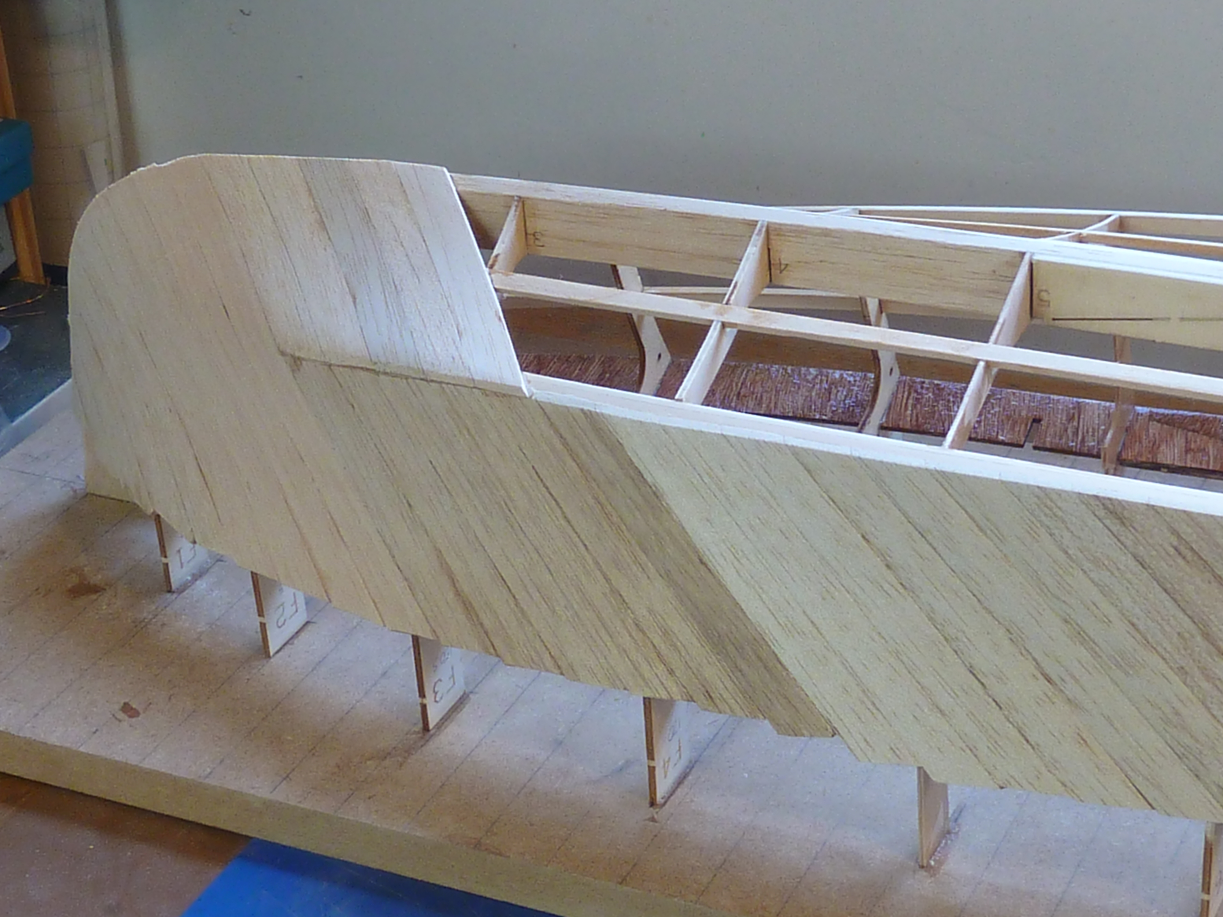
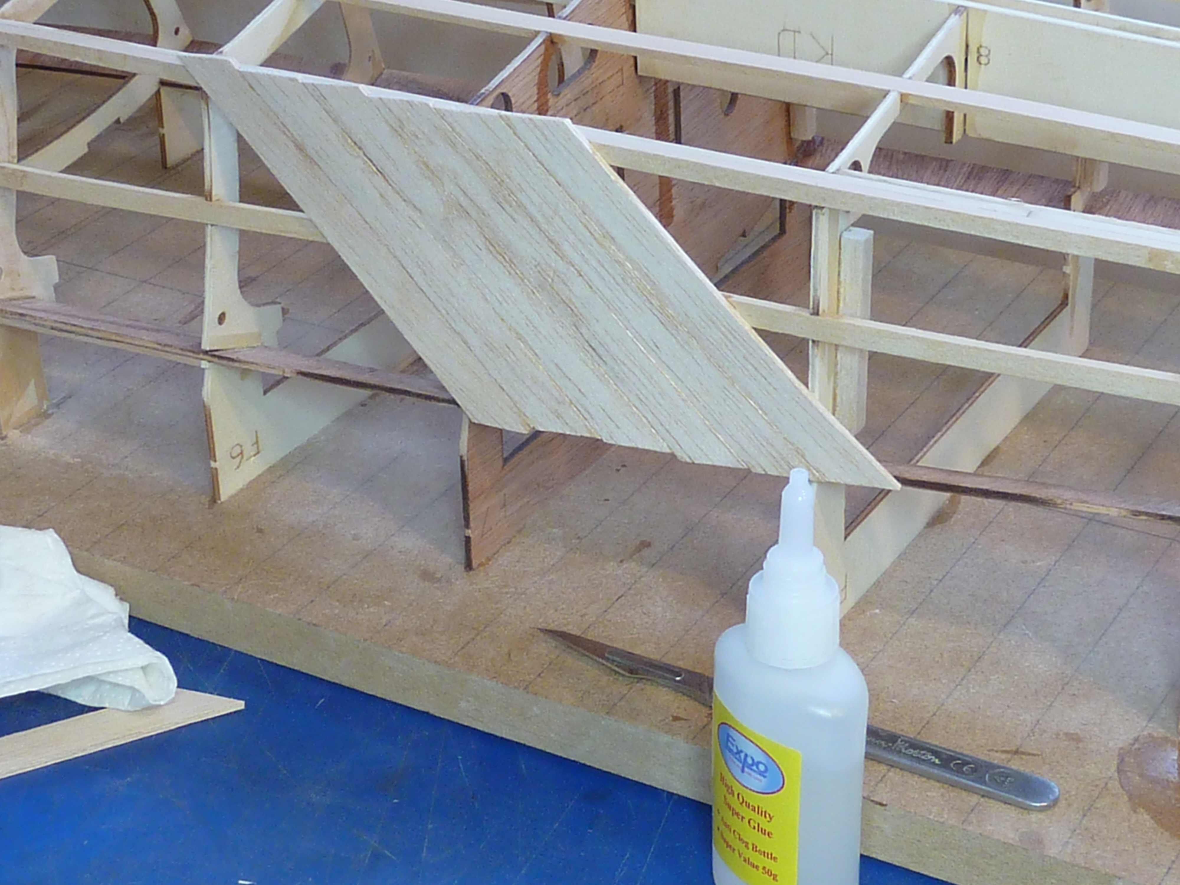
It does make a difference when you get to the bows though. The instructions have you follow the chine line all the way to the stem. However with the planks angling forward it becomes quite easy to do the bow section in one take, as shown in the picture.
I did examine pictures of the real boat quite carefully before adopting this approach as I was concerned that I was losing the definition of the chine, but it disappears on the real boat too around the same location.
I’m not certain, but this unintended modification may actually be an assembly improvement.
Having completed both sides, and sanded the plank ends true to the chine, I then planked the bottom of the hull. As I’d already effectively started at the bows, I worked back from there. Another deviation from the kit’s instructions. Living on the edge!
In order to get a nice straight join line down the centreline of the keel I laid the planks completely on one side slightly overlapping the centre. I then cut down the length of the keel vertically using a scalpel and 1m steel ruler.
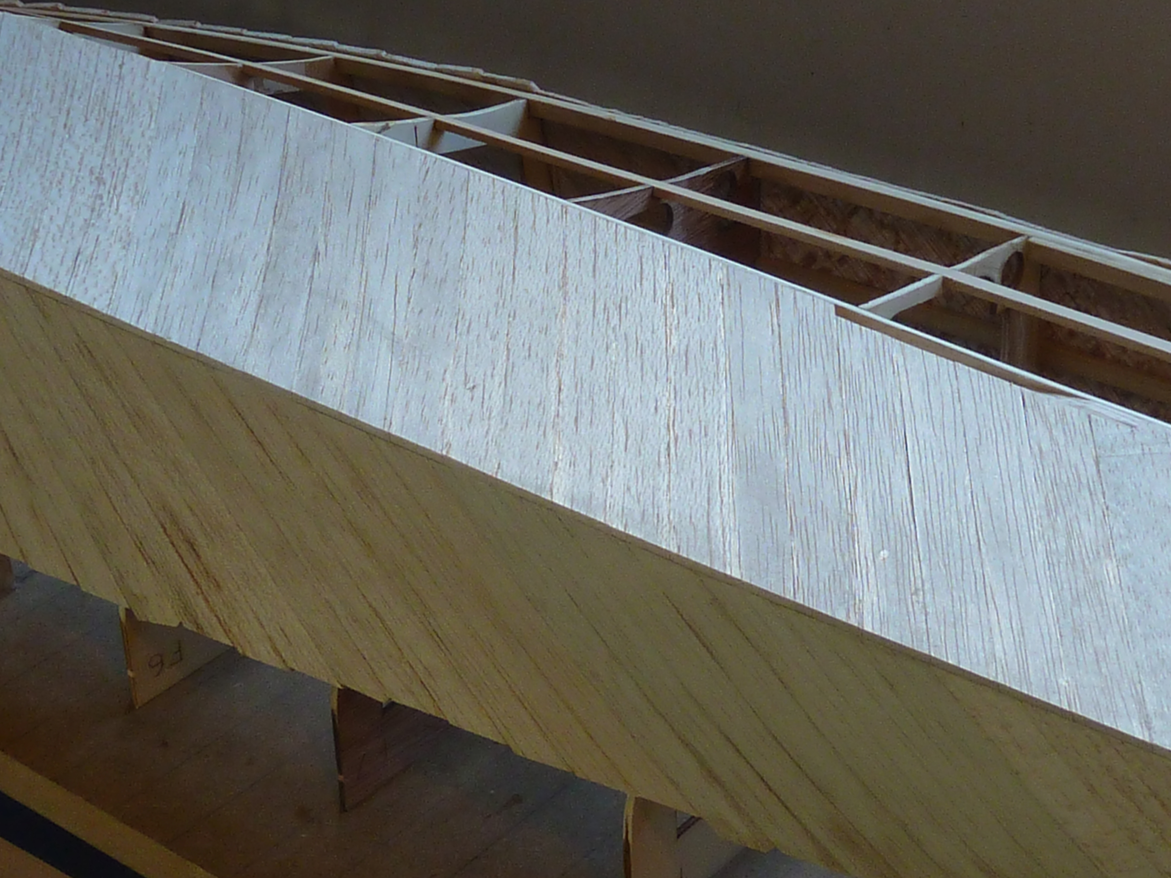
That gave me a lovely straight line to work to for the other side, not that it matters greatly as the join is completely hidden in the finished model. Still, pride in your work and all that…
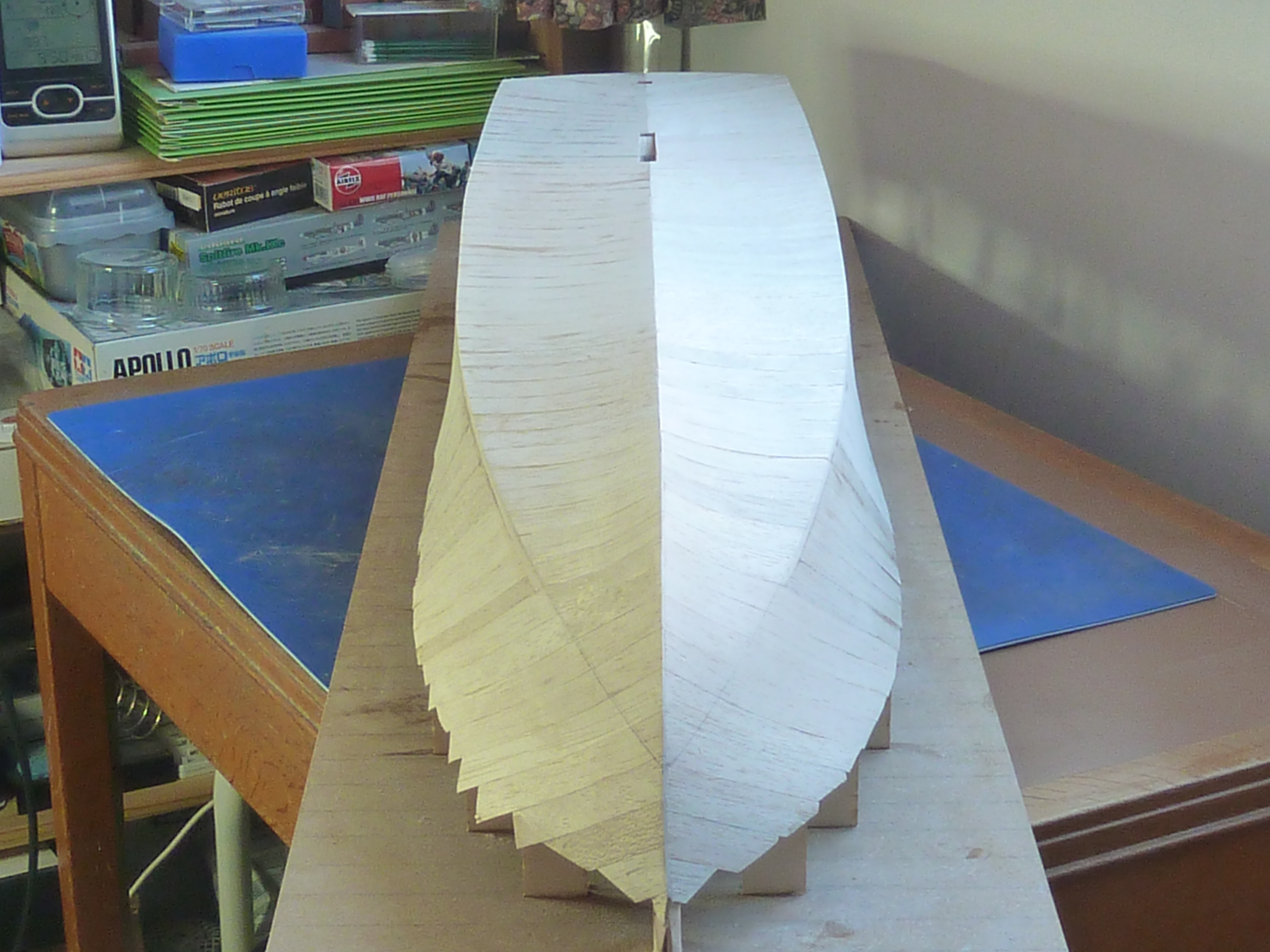
With the sub-planking complete I used the 1m steel ruler to project forward the chine line to the bows and drew it in, making sure both sides met at the bows.

That’s it for this post. Next I’ll get on to the final planking of the hull and construction of the cockpit area. Hopefully the post will appear a bit sooner than this one did.
‘Miss Severn’ 1922 Gold Cup Racer – Mack Models 1:8 (PART 2)
