I’ve finally got there. One post more than I thought I’d need, but the two engines are finally complete and a selection of photographs of them added to the galleries under the drop down menus at the top of the page.
There wasn’t much left to finish them really. The main activity required was the completion of the coolant hoses, and the installation of the exhaust studs.
As before the hoses were made up of three parts.
A wire core to make sure they keep the right shape during heating.
A polystyrene inner tube to give them the right diameter.
An outer sheath of black heat shrink tubing to give a true rubber appearance and thin wall thickness at the ends.
The black tube on the right of the picture is there to form the flared end on the coolant hoses, and is the same diameter as the lugs on the model. It was removed from the formed hose once the heat shrink tube had been shrunk to size.
Each hose was run to the model then measured up. A final version was then made from fresh materials, as I’ve found it is necessary to partially shrink the outer onto the assembly then bend it to shape. Once that’s complete you can remove any wrinkles in the outer by completing the shrinking operation. If you try to slide the heat shrink over a bent inner, like the one in the picture below, the inner wall of the curve wrinkles to an extent that can’t be remove entirely during the heat shrinking process.
Running a dummy hose to the model prior to making the final version.
The process is a bit laborious to be honest and caused me quite a bit of grief. In hindsight it would’ve been a much simpler option if I’d done it in conjunction with fitting the exhausts rather than after. As it was some choice epithets might have been uttered during the operation.
The hoses on the burgundy engine were by far the worst to do as the arrangement is more complex than on the black one because of the location of the water pump.
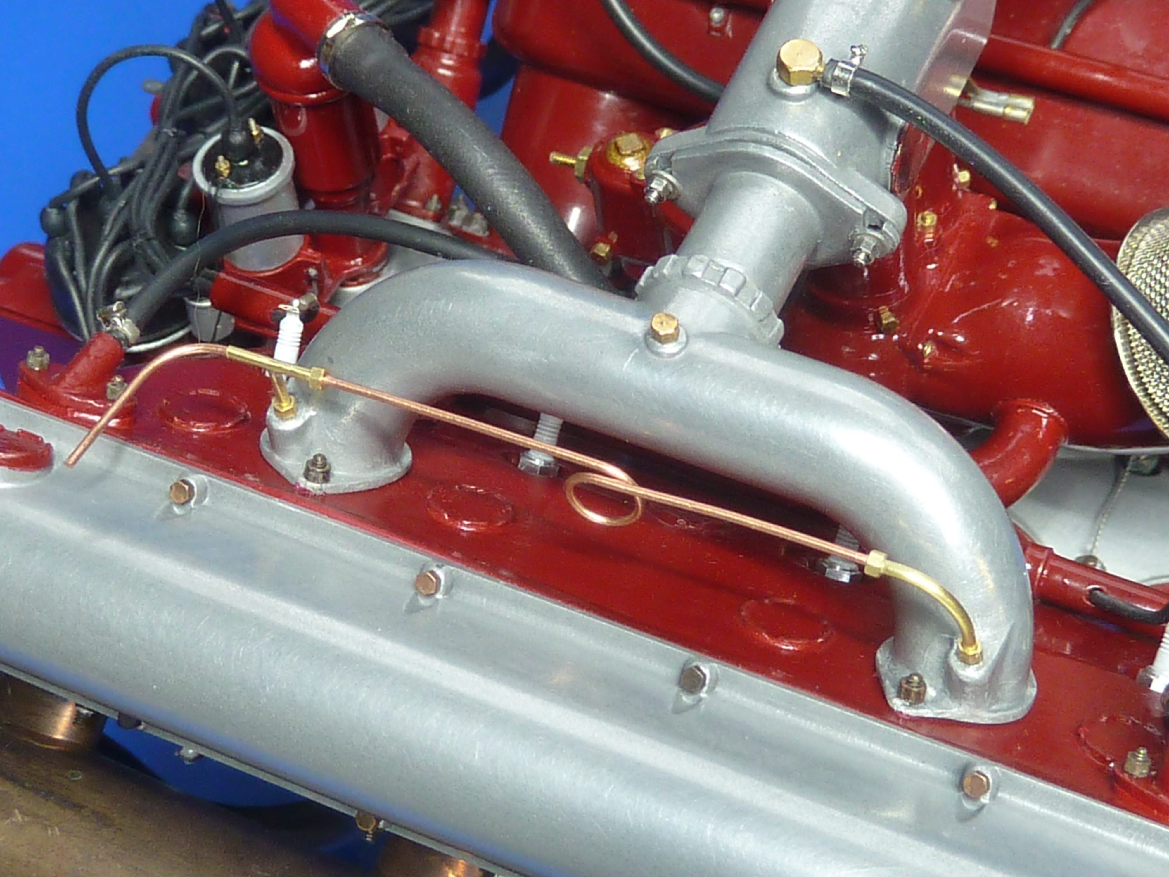
Other minor work included fitting the cylinder priming pipework on the top of the burgundy engine. For some reason this was quite difficult, which was a surprise as it was relatively straightforward on the black one and they are supposedly identical. Probably just an off day at the modelling desk.
The unfinished left hand end on the priming pipework will be completed once the engine is installed in the ‘Miss Severn’ model.
The coolant hoses also required the making of several batches of faux jubilee clips. These are fairly simple but take time. An appropriately sized tube is cut into thin sections and some thin (0.8mm OD) tube soldered to the rim. The whole assemble is bright nickel plated. As a final flourish a brass pin which has had its head slotted and then been bright nickel plated is glued into the cross tube to look like the screw mechanism.
The very last operation was to add the exhaust mounting studs. These are just glued on and have no physical function. They were made from Some M1 threaded rod with M1.0 brass nuts glued in place. The whole affair was then burnished to make them dark. Tedious and unexciting work. 32 required per engine.
If I were make another of these models I’d approach the exhausts in quite a different way I think. I’d keep the flanges separate from the exhausts themselves, which I have seen on some engines. That would make getting everything aligned much, much easier and would allow the studs to be actually glued into the block.
That’s it for these engines then. A lot of fun to make, but much more involved than I thought it would be. I’d secretly envisaged it taking about half the time it has. I wasted a lot of time and effort though trying to master white metal casting of the aluminium parts before admitting defeat and using the cold casting technique. Now that I know what I’m doing and have all of the moulds to hand I think I could build another engine in 250 – 300 hours. I might even do that as I’d like to have an unmodified aviation version too. They’re not cheap though when you add up the costs of all the nuts and bolts.
Here are some pictures of the finished models. There are a few more in the gallery pages too.
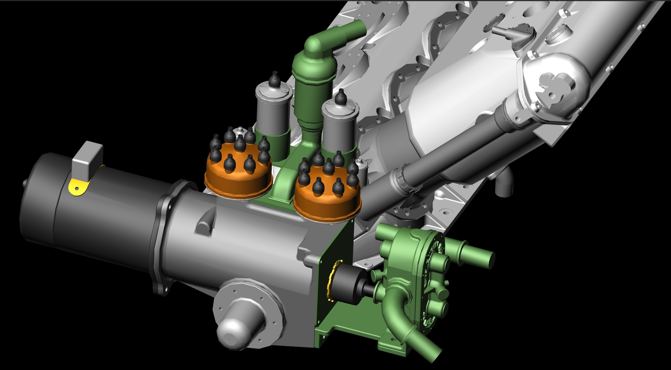
There is a CAD version of the aviation engine ready to go. I just need to get the exhausts printed off…
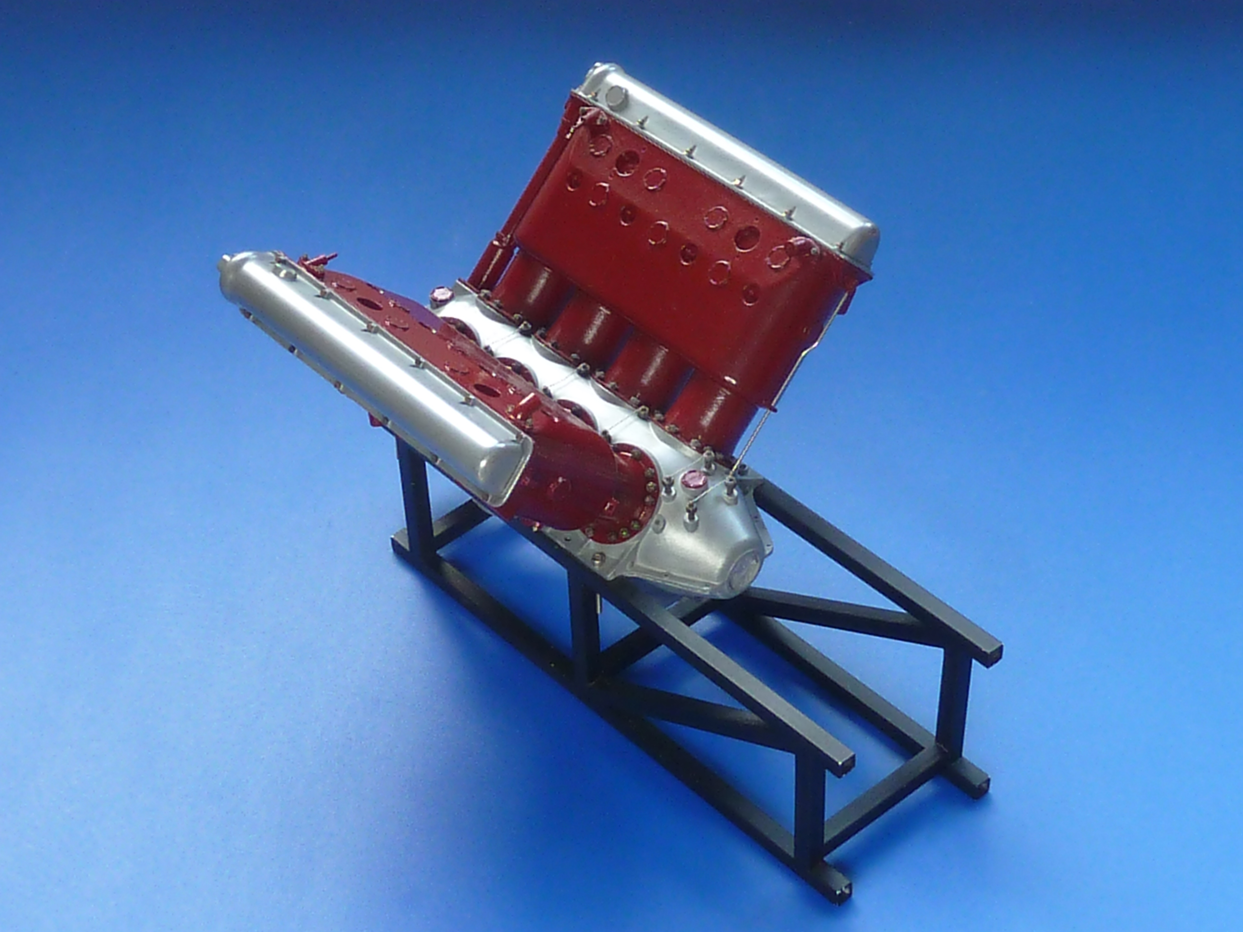
Aircraft version on the engine in CAD, which might get built one day.
Aircraft version on the engine in CAD, which might get built one day.
I had hoped that this would be the last post on the building of these engines, but they will not lie down and give in. The exhausts in particular have been giving me grief.
Given how large they are, and the visual impact of that, I wanted them to have a real metal feel to them. I didn’t think I’d be able to achieve that with painting, and hence decided to build them out of copper and brass (see previous post). They’ve turned out to be some of the most complex soldered items I’ve ever made, but I got there in the end.
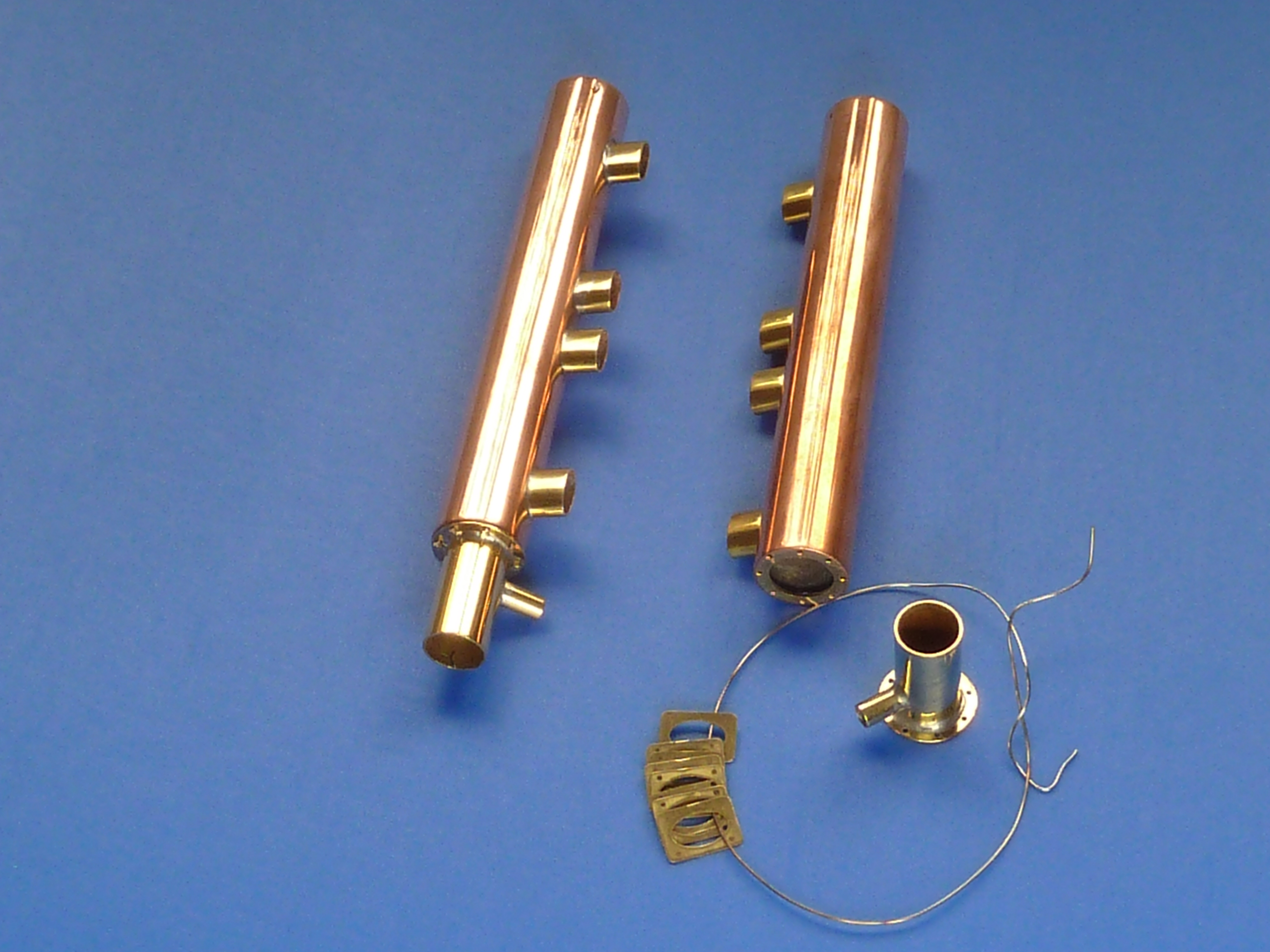
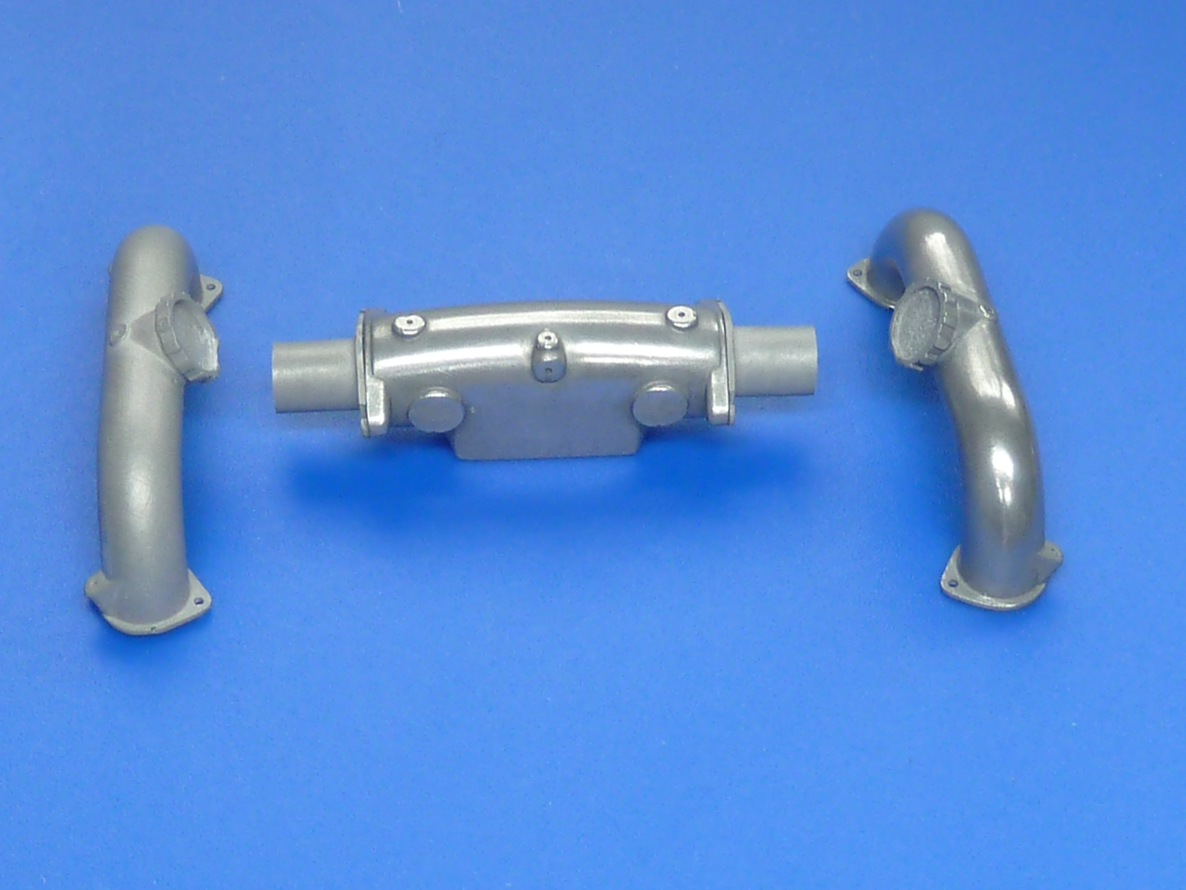
Below are the basic items for the burgundy engine which will be going in the Miss Severn type model. They are complete and copper plated, but do not have the inlet and outlet water cooling pipes fitted.
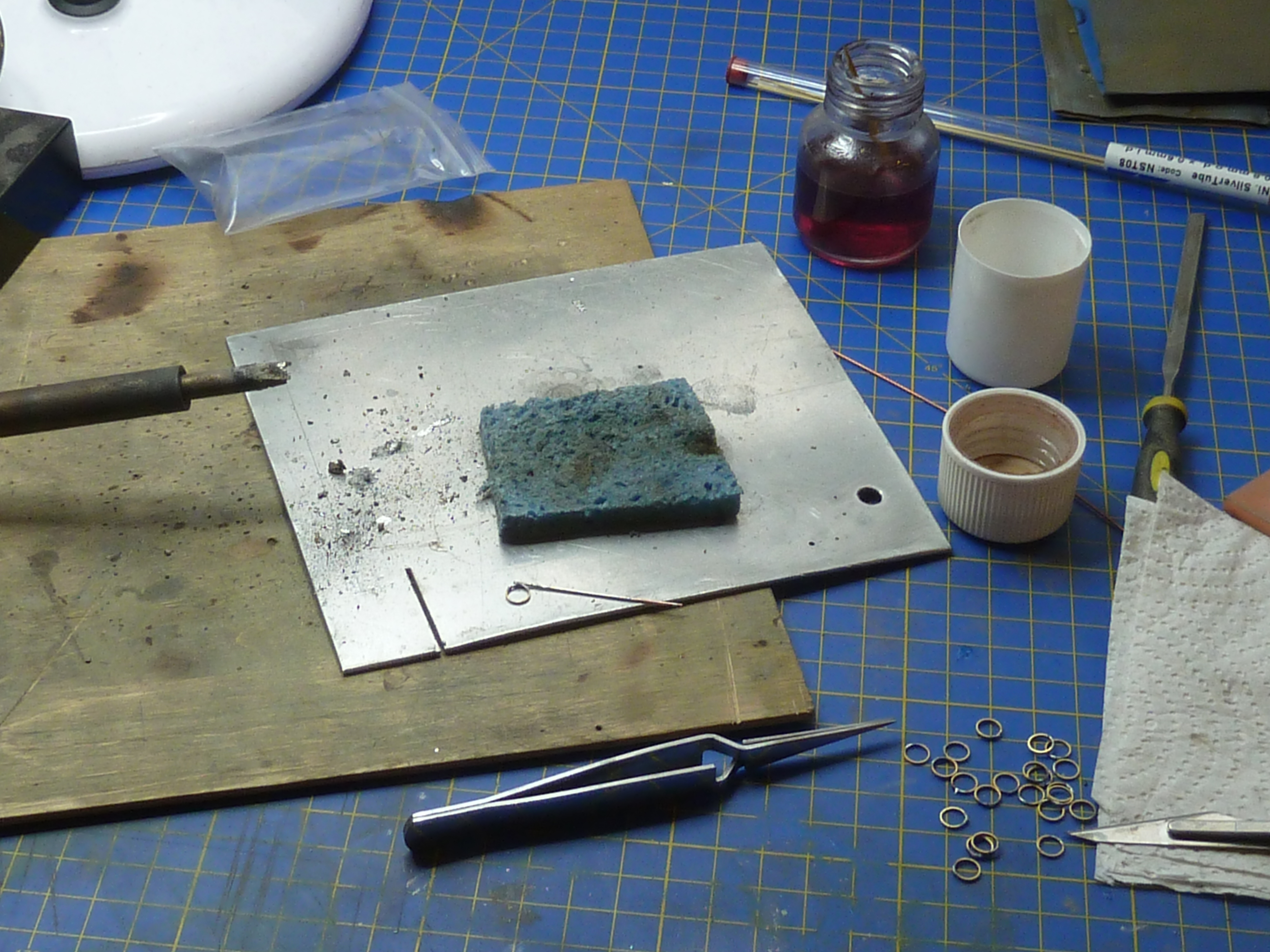
I’m aware that a lot of my pictures show things after they’ve been cleaned up, so here is a picture of one of the exhausts during assembly.
And after clean up, but before plating.
I wanted to plate them to give a homogenous copper look. I have seen welded copper exhausts on one restored boat from this era so, if designed correctly, they must be able to withstand the heat. I doubt brass ever would though, so my headers needed hiding under copper plate. For the doubters, remember they are bolted to an aluminium casting so if your heat management is right, they must be able to work. Aluminium melts about 400°C (750°F) before copper after all.
After plating with copper I wanted to give them an aged rather than a new polished look. I hit YouTube and tried a number of techniques found there.
I don’t know why, possibly because of the ‘brighteners’ in the copper plating solution, but Sodium Bicarbonate had zero impact. I even left the samples on a radiator overnight in a jar with bicarb solution in the bottom, but they were all still lovely and shiny the morning after. Acetic and citric acids were also tested (OK, vinegar and lemon juice to you) but didn’t really deliver. Immersion in an ammonia solution was exactly the opposite and just way too much. Verdigris all over the place in a very short time. Using burnishing solution worked quite nicely, but gave a blue/black patina, not the brown I was after.
Copper pipe naturally aged by leaving it, lonely and unloved, in my garage for 25 years vs the one on the right ‘aged’ in burnishing fluid.
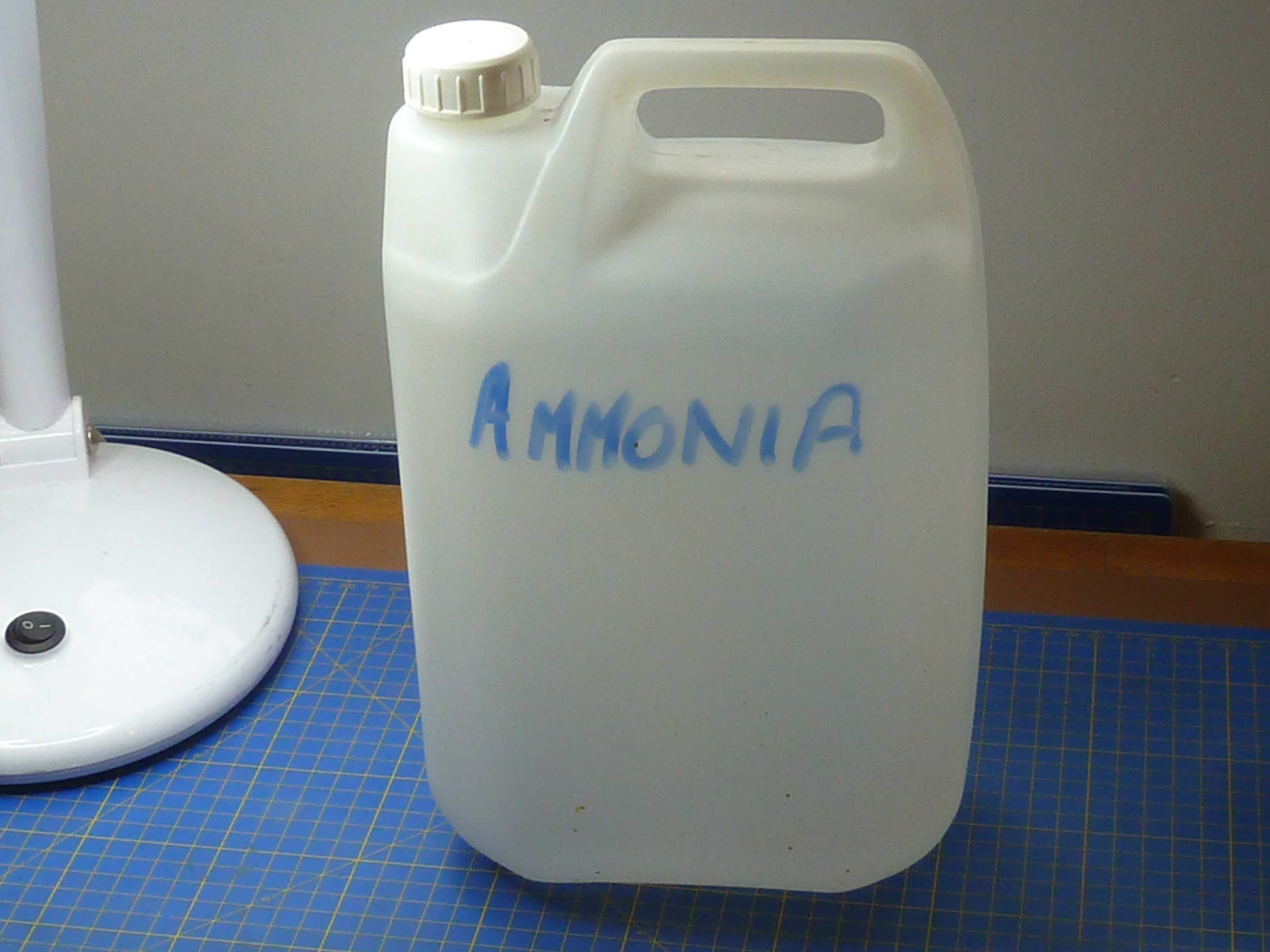
In the end I found hanging the copper items in an ammonia vapour bath was the best option. You need to make absolutely sure you don’t get any of the neat ammonia solution on the samples though, as that leads to verdigris spots.
That all sounds quite technical and posh, but the reality was a 5L plastic can with a cup full of ammonia solution (34% by vol) in the bottom. The parts were hung off the rim on wires with the top popped back on to limit evaporation. I left the parts in there for about 2 hours, but the temperature in my garage was about 5°C (41°F) at the time. I doubt they’d need that long in summer.
Having proved the method on some samples, I put the black engine’s exhausts in to treat them. It was a disaster… I’m not sure what happened, but the copper plate started to flake off all over when I removed them. Something must’ve contaminated the surface prior to plating, but I’ve no real idea what. Perhaps my acetone had something in it or the cleaning brush did.
Ho hum…
Whatever, I had an enjoyable afternoon removing all of the copper plate and cleaning up to start again from scratch. Thankfully that went without any further problems.
The burgundy engine has a slightly different and more complex cooling arrangement to the black one, primarily because of the alternative ‘distributor’ rear end arrangement. That required some pipes to feed the water jacket from the pump.
I tried making them from tube, but couldn’t get the tight radius bends I wanted without the tube collapsing. In the end I made them out of solid 4mm rod. Say nothing and no one will know!
Water jacket feed pipes.
Some before and after pictures of the soldering ops.
Risky stuff, as I only used one type of solder, so there was a very real risk of unsoldering old parts while I was adding the new ones.
(I mainly use a cook’s blowtorch for my soldering).
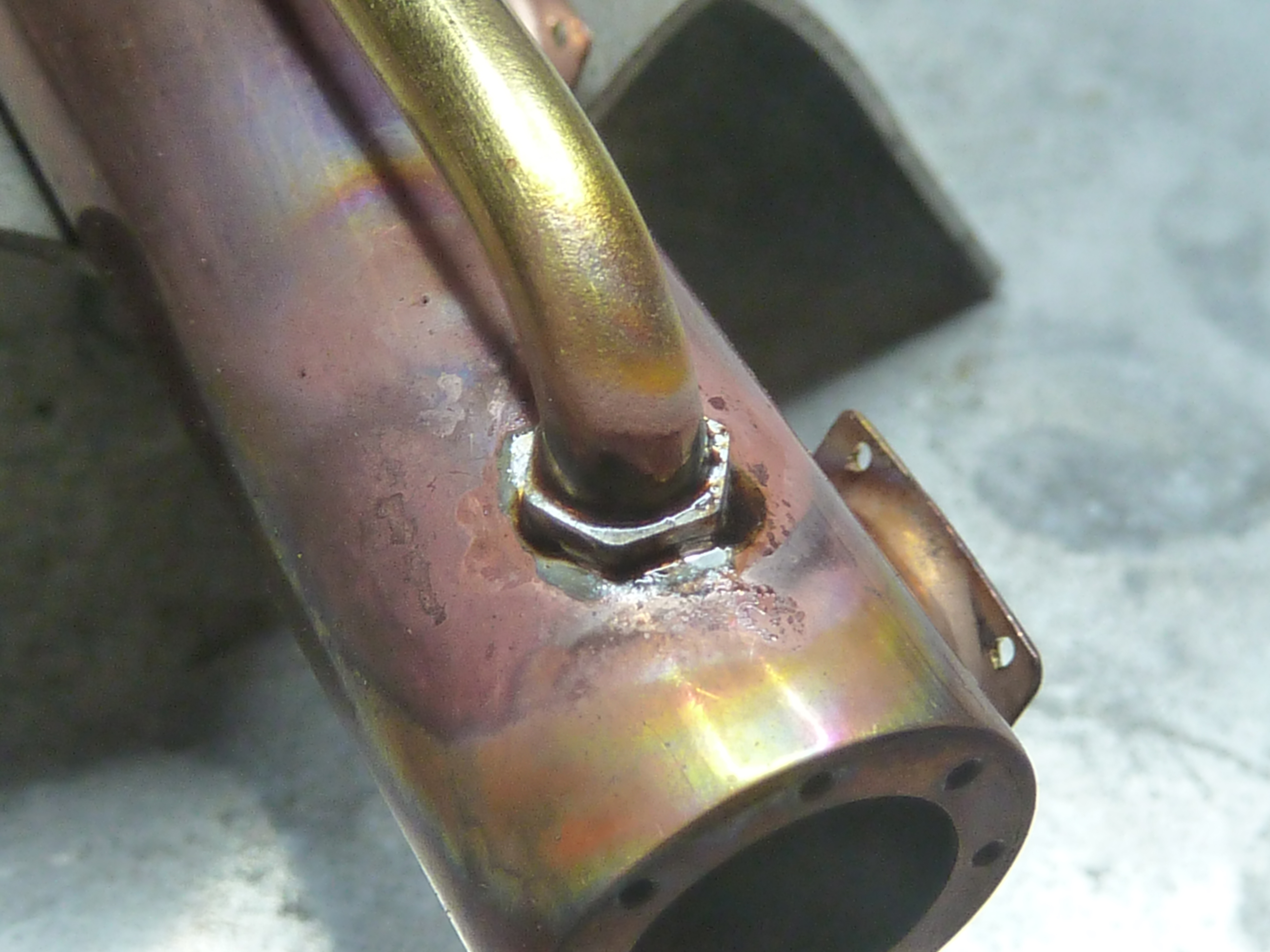
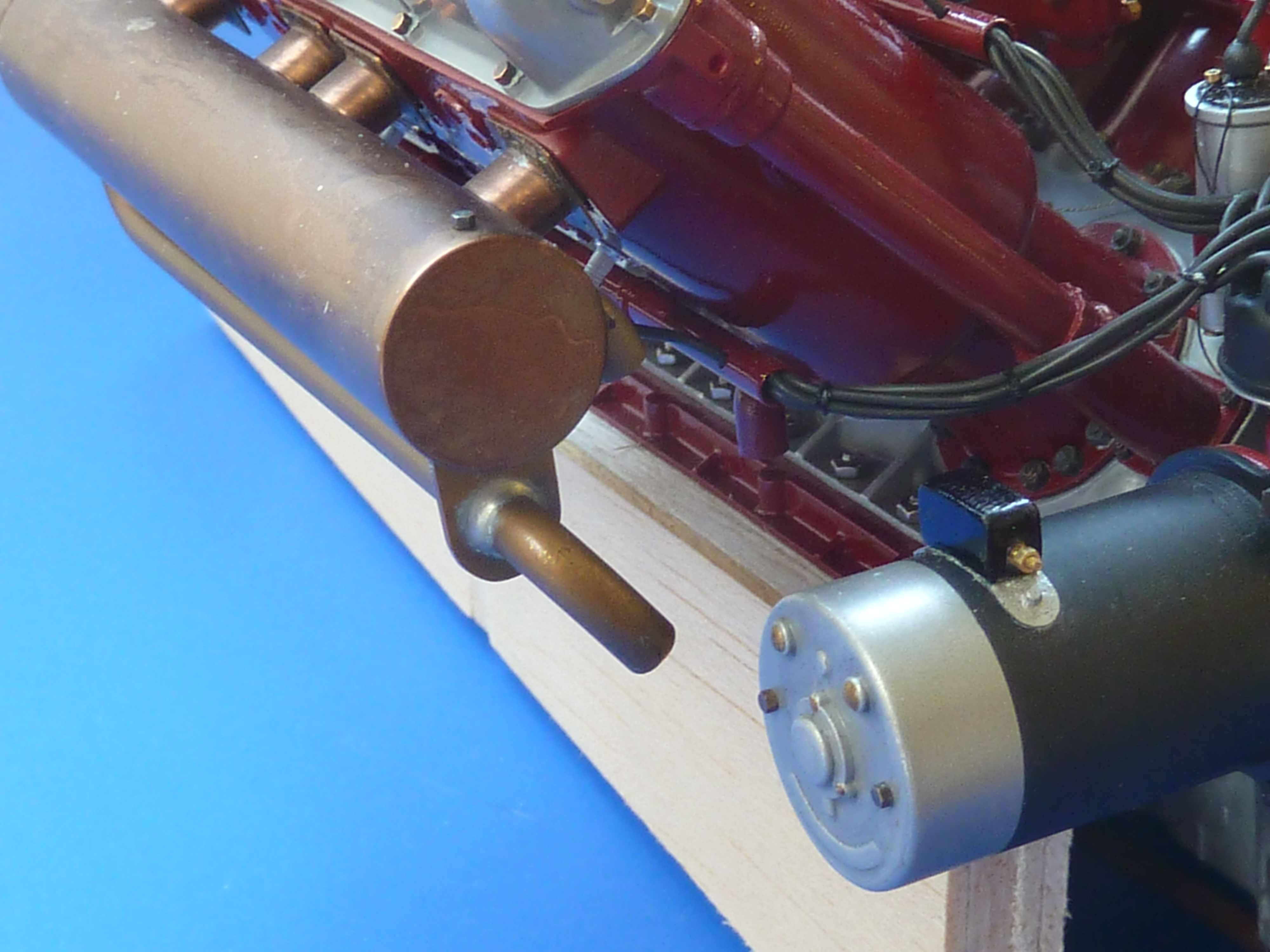
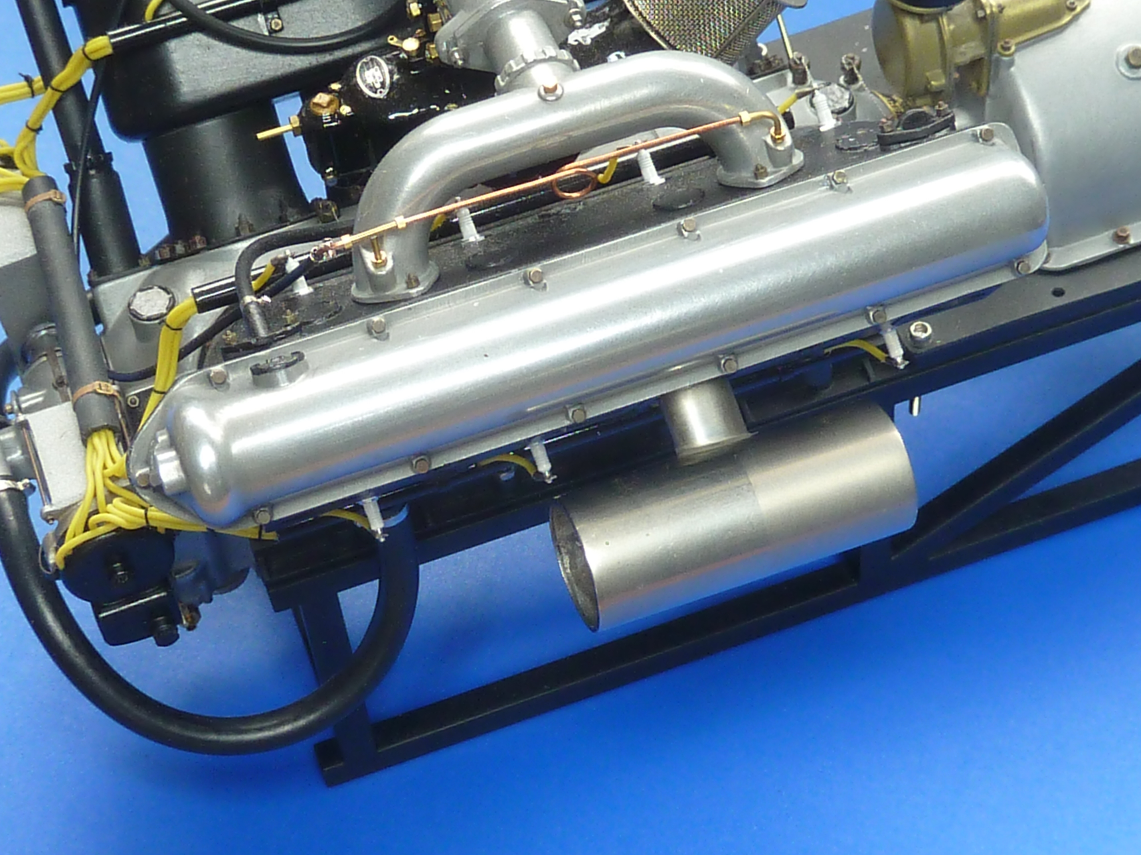
The end result after clean up and a couple of hours in the ammonia vapour bath. The steel spigots are there to mount the exhaust to the engine. The ‘mounting’ bolts will just be for show. The small water outlet at this end of the picture is actually a cold cast bronze part. I thought trying to solder a copper part on there was just pushing my luck too far.
And finally fitted to the engine.
I just need to finish off the rubber hoses to complete the build. They will be similar to those on the black engine.
In addition to the exhausts I’ve also got around to finishing off the clutch. I call it that because I can’t think what else it would be, but I’m not actually certain of it. The thing has a massive mechanical advantage built in to it though, and it’s the only mechanism I can think of that would require that.
If you recall from my previous post I’d designed it in CAD and was intending to build it from photoetched parts.
The first version looked a bit weedy compared to the pics of the real thing, but did at least serve to prove the concept.
Clutch made from 0.9mm brass sheet.
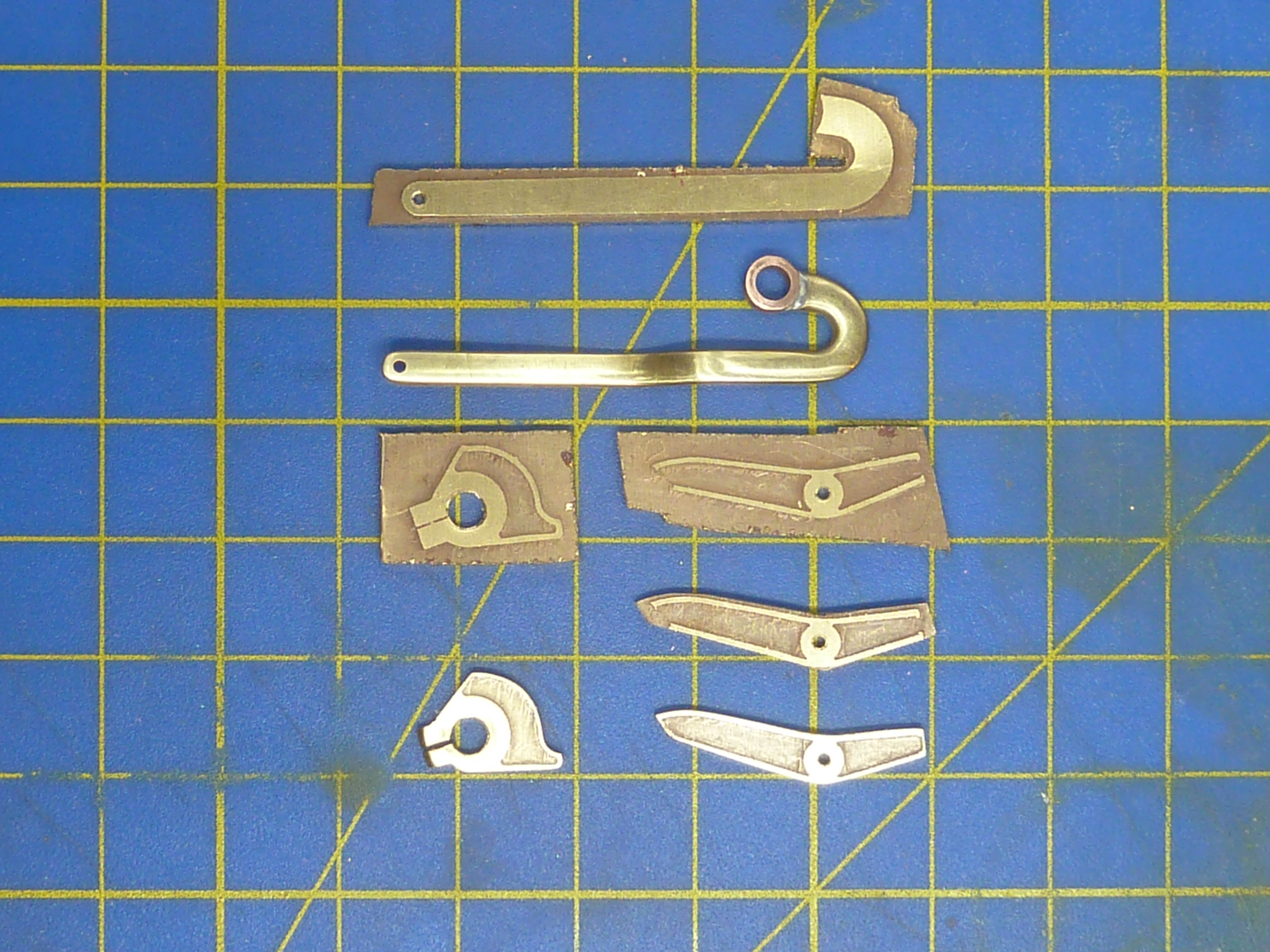
The parts were eventually made from etched 1.5mm brass sheet.
The parts in various states of completion.
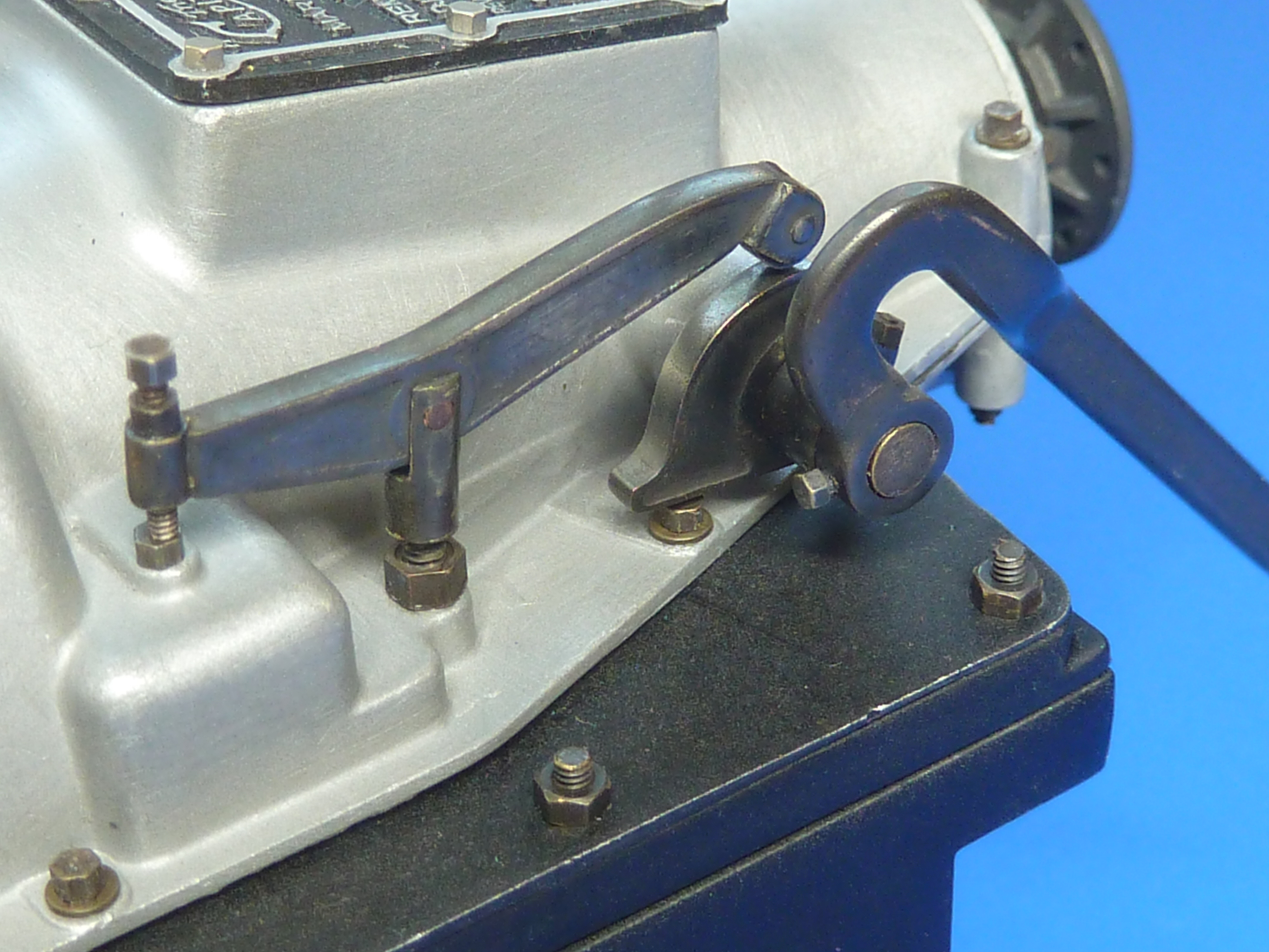
After burnishing they were installed on both engines. The thicker section looks much more in scale.
Final version of the clutch release mechanism. The lever turns the rising cam which in turn lifts the central pillar. The bolt on the left hand end provides and adjustable pivot point.
Another area that was finally completed was the carburettor controls on the burgundy engine. The black engine’s controls are much simpler as they don’t have to connect to anything and can be left as they were on an ‘as delivered’ engine.
However, as the burgundy one is going in the boat it does needs connections that can properly link to the cockpit controls. To that end I built a small brass confection out of sheet and tube to simulate some sort of Bowden cable arrangement.
I just need to run some thing black wires into the tubes once it’s installed in the boat.
I’ve finally got around to adding a maker’s nameplate to the burgundy engine too.
As the black engine will be a stand alone model in a little glass case I’ve made some name plates to go with it. They are the usual etched brass affairs, and are replicas of the plates actually fitted on the model. In fact the etch masks were made using the same print files scaled up.
Etched, filed and drilled.
Stained and lacquered.
Having installed the exhausts on the burgundy engine it was possible to start test fitting the thing in the Miss Severn model. I’d already checked the fit with my rough and ready 3D printed space model, but it was still a bit of a relief to find it went in without any problems.
I can now start to plan the layout of the engine bay. One of the main features of this will be the exhaust run to connect up with the kit’s in the cockpit. That requires some form of flexible coupling and I’m intending to use some braided oil pipe that I have to hand. A rough mock up of the what is planned is shown below and is based on some of the high temp piping that I have seen installed in aircraft.
Further updates on the engine bay fitting and equipping will appear a under the ‘Miss Severn’ series on this blog.
There will be one more engine one though, to complete the black engine’s build log.
Well hopefully this will be one of the last posts on these engines and I’ll soon be able to get back to completing the Miss Severn and Chris Craft models. The engine diversion has been much longer than I anticipated and I’ve had to remind myself a few times that the actual aim is to build the boat model, of which the engine is only a part.
If you recall from my previous post, I was messing about with cooling pipes as the size I had intended to fit looked too large on the model.
I spent most of a day rifling through my odds and ends boxes trying to find something that would do the job. Attempting to satisfy the need for a thin wall thickness and small diameter was not easy, especially as some of the pipes have to go in quite tight curves. Thin wall and tight curves equals collapsed pipe. I’d also already had problems with the pipes fitted to the black engine putting too much strain on the mounting points and pulling them off, so whatever the solution was it had to also be low stress.
Hence, I really needed the pipes to be pre-formed to shape as well.
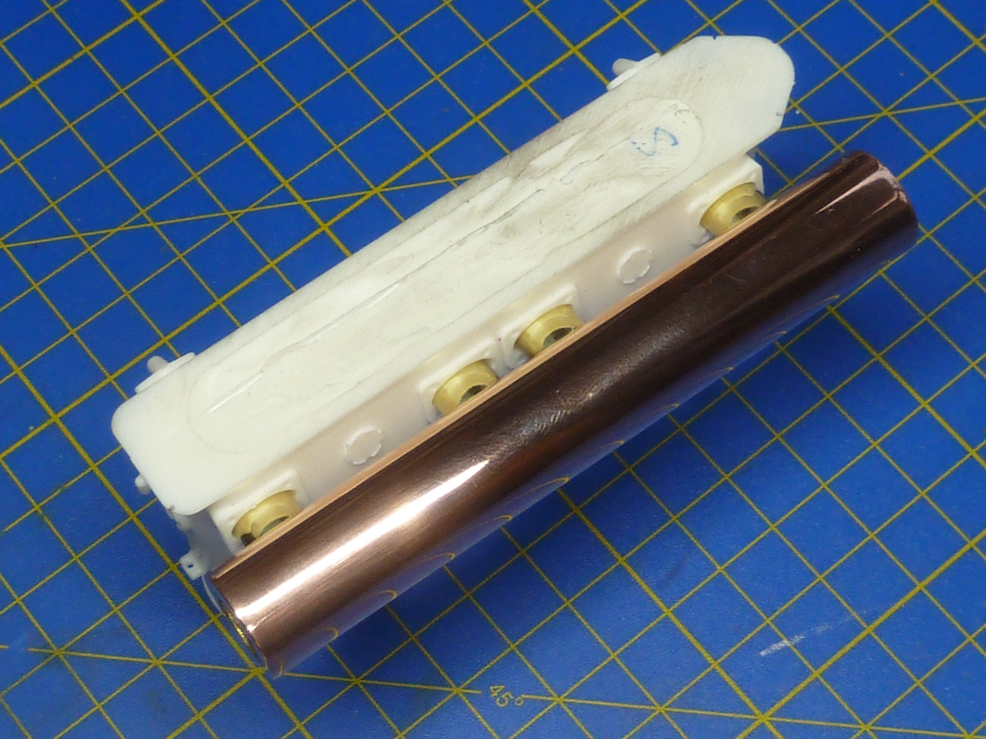
After a day of testing various ideas I gradually homed in on a compound solution. The pipe run was formed from some polystyrene tube with a copper wire core.
White polystyrene tube with a copper core was used to form the pipes to the required shape. Then black heatshrink was slipped over the formed pipe. The copper stops it changing shape under the heat gun, and the black tube on the right allows a flared end to be formed in the heatshrink. Heatshrink without adhesive means the latter tube can easily be removed when everything has cooled.
Heating the whole affair allowed me to bend it to the desired shape, and the copper core made sure it held that shape as it cooled. It also meant there was no chance of the tube collapsing in tight bends.
Once formed black heatshrink was slipped over the whole assembly and shrunk on with a heat gun. To allow the pipe to mate to the parts already on the engine I placed another, slightly larger, tube over the end of the copper core to give me a slightly flared end. That was then removed. Obviously you need to use heatshrink without glue for this process.
Below is a picture of the first pipe made this way. It is actually the crankcase vent connection to the carb inlet rather than part of the cooling system.
I’ve also made a proof of concept prototype of the cooling outlet into the exhausts (the cooling system is a total loss/open loop design as are most boats, and the water is dumped overboard using the exhausts). I won’t be able to finalise that part of the design until the exhausts are fitted.
Having finally resolved the piping conundrum I could get down to making all of the jubilee clips I’d need. They are just some 0.8mm copper tube soldered to a thin ring cut from brass tube.
The assembly is then cleaned and bright nickel plated, and as a final flourish, a slotted 0.6mm panel pin is glued in the cross tube to simulate the adjustment screw.
After a couple of days work I found myself in possession of…
Which doesn’t look much for the effort required. Ho-hum… onward and upward.
As a quick side activity while various parts were electrocleaning or plating, I made some more of the ID plates for the engine. One for the side of the sump and one for the carb. These were made as before: a custom decal applied to brass or aluminium sheet.
There is another ‘Simplex’ label I’ve seen mounted at the back of the sump, but I’m not sure it was fitted when the ‘Hispano-Suiza Licence Built’ was fitted on the side, so I haven’t added that (yet). More research needed.
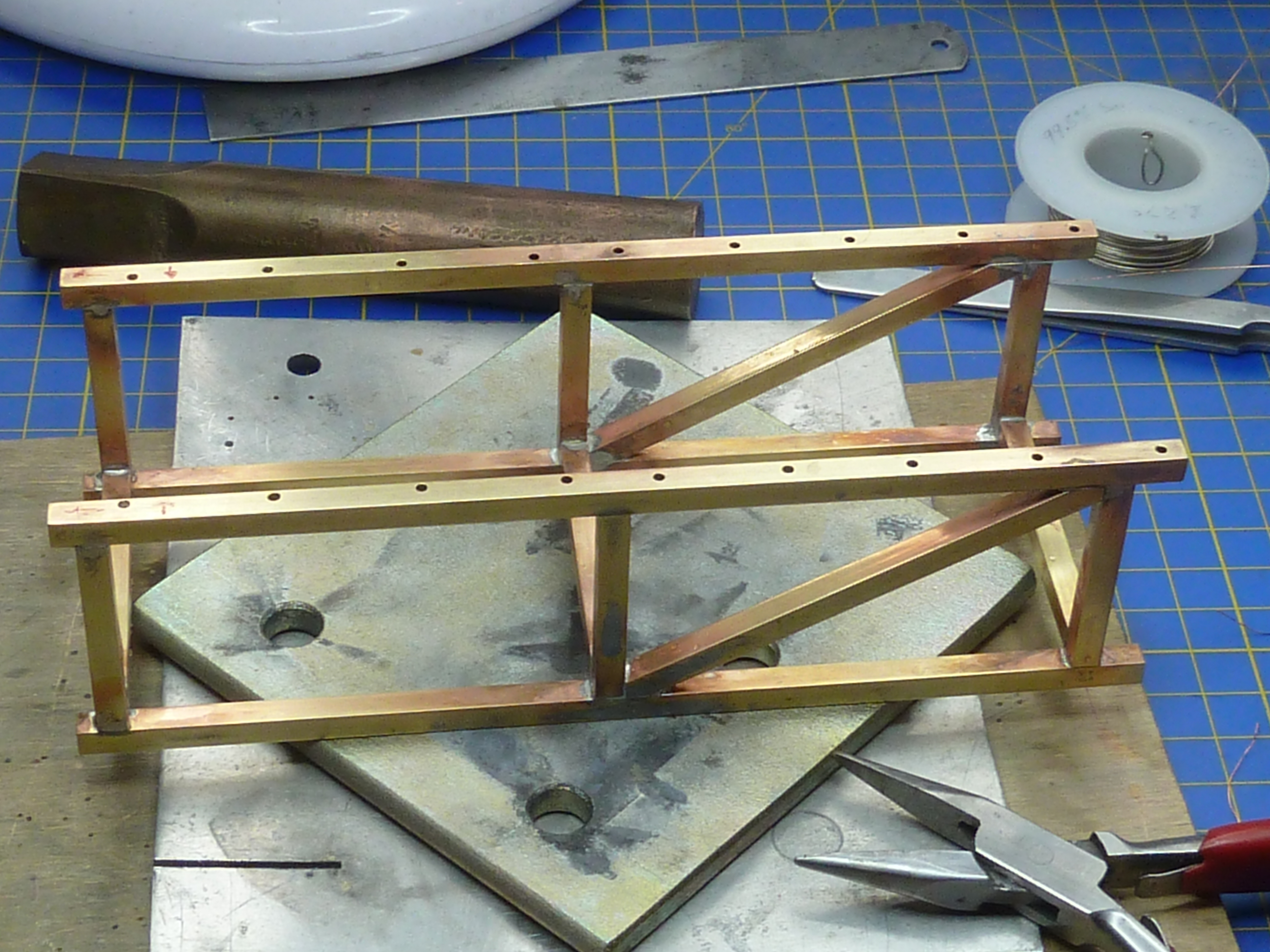
As the burgundy engine had now reached the stage where it needed to be mated with its gearbox on the subframe I needed a second build stand that would take that whole assembly. Rather than build another gash one out of plastic I decided to swipe the one holding the black engine as that was already a bit battered from constant handling.
As the black engine was not far from completion I decided to transfer that to its final presentation stand which was made out of square section brass tube.
There’s £15s worth of brass tube in that little stand. £15!
The stand was painted with an etch primer, then finished in satin black from a rattle can.
Fitting the correct mounting bolts for the engine was a barrel of laughs. They are really quite hard to get at. The first one (of 14) took 45 minutes. Oh, deep joy…
Things did speed up quite a bit after I fashioned a few wooden wedges to hold bolts in place while nuts were fitted, but the job did severely test my patience. It really needs three 1/8th scale hands, especially as you are desperately trying not to scratch the castings or nuts in the process.
Having got both engines mounted on their subframes I could move on to finishing the detailing of the gearboxes. Key to that was installing the starter motors. I had previously cold cast the parts in aluminium, but some parts were definitely brass judging from pictures, so I remade them in cold cast brass.
The parts were then fitted in place and the detailing nuts and boots added.
The burgundy engine’s gearbox has a cut-out at the rear to allow it to fit around the stuffing box already installed in Miss Severn. The rear of the gearbox will actually be hidden deep in the bowels of the model and the cut-out invisible.
Having sorted the piping problems and got both engines mated to their gearboxes I could move on to the exhausts. These were water cooled and appear to be specific to each installation. I’ve certainly never seen a ‘common’ design around.
The big difficulty with the exhausts was the oval header pipes. One of the distinctive differences between the Hispano-Suiza 8B engines in the SE5a, Spad etc. and the 8F is the change from nice, simple, easy to find circular pipe, to rocking-horsesque oval on the latter.
I did try just squeezing some round pipe in the vice, but found that gave me a race track shape rather than a true oval. In the end I decided to make some custom formers using my 3D printer. The PLA plastic it uses it quite tough and strong enough to form annealed thin wall brass tube.
I calculated the size of tube required to form the oval based on the assumption that they’d have common circumferences and it came out at 7.1mm diameter. So, 7mm diameter tube it was. A former design was quickly knocked up in CAD and printed. After a few trials revealed that the mathematically ideal solution wasn’t in real life, so the design was slightly tweaked and reprinted. Quick to type, but that all consumed another day’s work.
15mm copper pipe for the water jacket of the exhaust and 7mm brass tube cut to length for the oval headers. The Mk.II forming press is in the background.
Using the slightly undersized pipe to form the headers did mean that all the lovely mounting flanges that I’d photoetched previously were now a slack fit and needed to be remade. So a tweaked etch mask and more etching…
The basic exhausts prior to having the mounting flanges soldered on.
And somewhat to my surprise it all fitted.
One of the engine’s discarded test castings was used to check the fit of the exhausts as they were assembled.
Here is one of the exhausts mocked-up on the black engine.
The only remaining question is how to finish the exhausts. I’d always assumed they’d be nickel plated in some way. To that end I knocked up a test piece to gauge which looked best, the options being:
Bright nickel plated on a polished finish.
Bright nickel plated on a brushed finish.
Dull nickel plated on a polished finish.
Dull nickel plated on a brushed finish.
The bright nickel on brushed looked awful and was right out. The ‘chrome’ finish was OK, but not really in scale.
Bright nickel plate. The left half of the tube has a brushed finish and the right polished.
There wasn’t much to choose between the two dull finishes, though dull on brushed had the edge.
Dull nickel plate. Left half of the tube has a polished surface and the right brushed.
Having mocked-up up the exhausts on the engine, the natural copper finish was actually quite nice on it’s own, and I have seen at least one boat restoration from this era where welded copper exhausts were fitted. Cost was not mentioned!
It was suggested that an aged natural copper finish might look good, so I’ve decided to give that a go. If it doesn’t work out I can always just clean things up and nickel plate anyway. I’ll let you know next time…
I’ve also been musing over how to install the exhausts in the actual Miss Severn model. Not surprisingly the faux exhausts in the model don’t line up exactly with the engine’s, and a small translation section is required (the S-bend in the CAD rendering below).
Based on my aircraft experience I also assume that the exhaust system would have some sort of flexible anti-vibration part to isolate it from the hull and it seemed logical to combine the two.
At the moment I’m working on the idea of using some braided pipe to form the link piece. I’m not 100% convinced yet though as the braid is perhaps a little overscale.
The other main activity that is ongoing to finish the models concerns the clutch mechanism. I have very few pictures of this and there has been a lot of supposition going on in designing it (that it’s the clutch is supposition for what it’s worth). In fact it took me about an hour of staring at the few pictures I have to work out how the thing functioned at all. It’s one of those things where it’s blindingly obvious when you know what you are looking at, but quite opaque otherwise.
Whatever, the design is complete and just needs to be made. I’m not certain how I’ll do that yet, but photoetch is top of my list.
The clutch release mechanism in CAD.
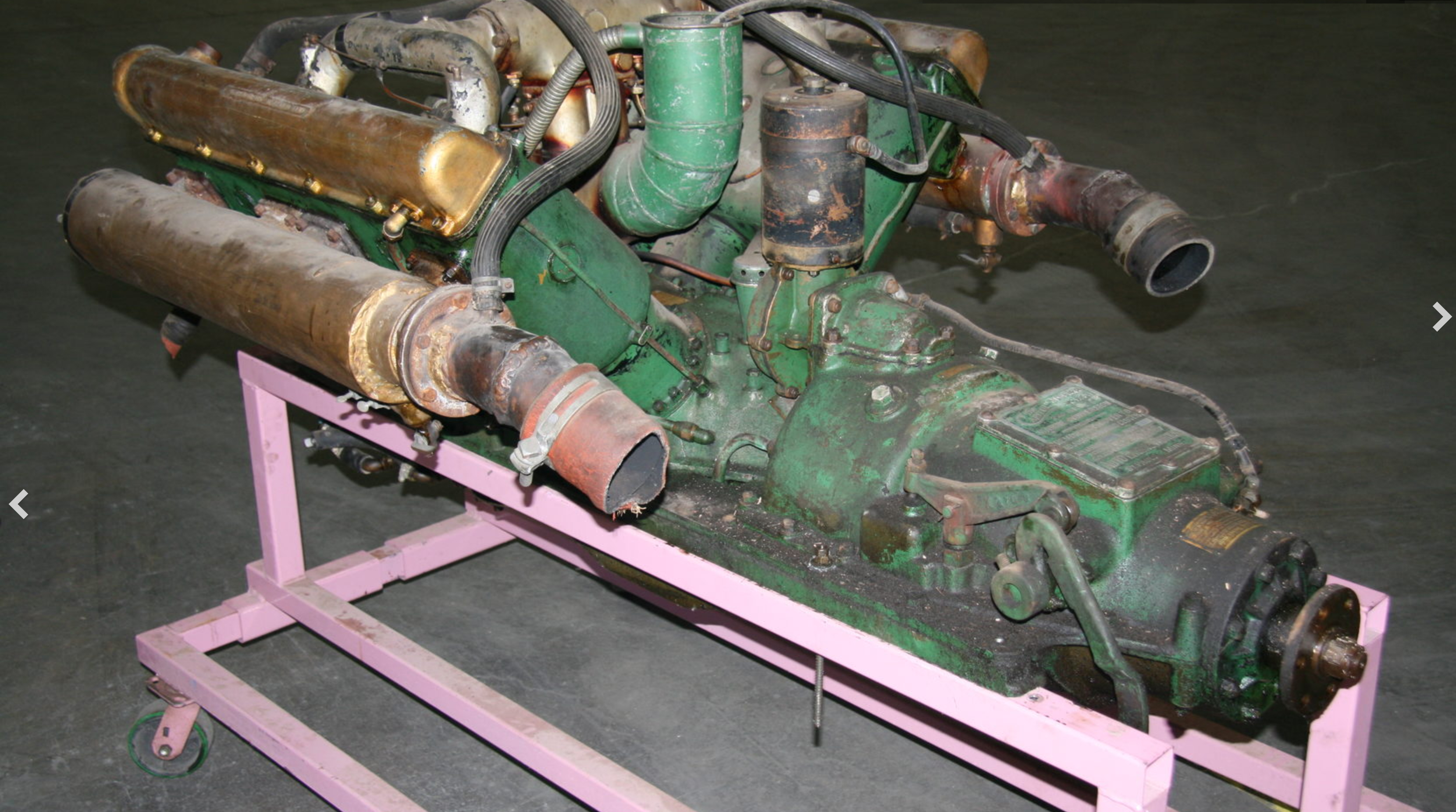
One of the few pictures of the real thing that I’ve found. It’s of an engine that was auctioned by Mecum Auctions..
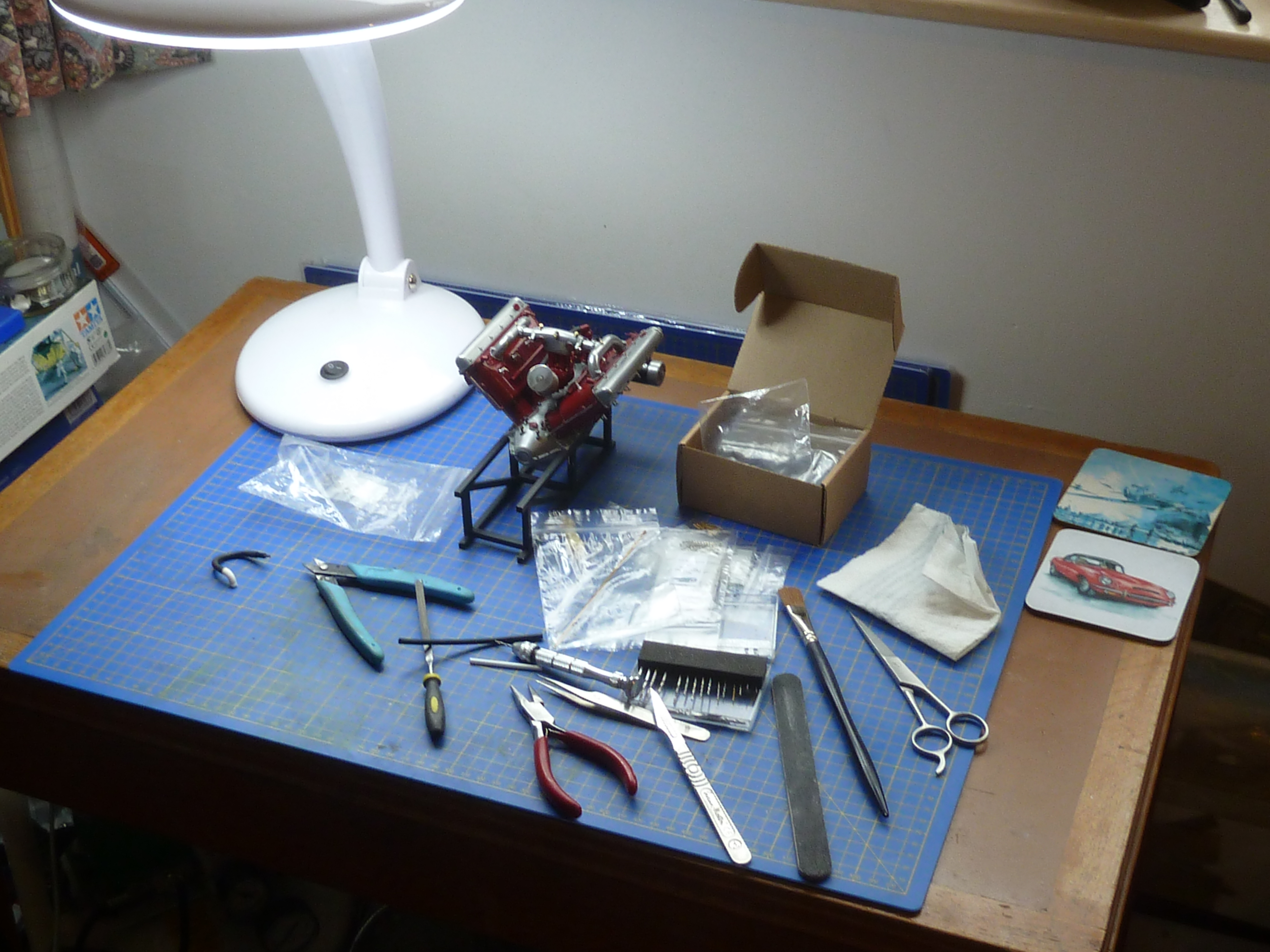
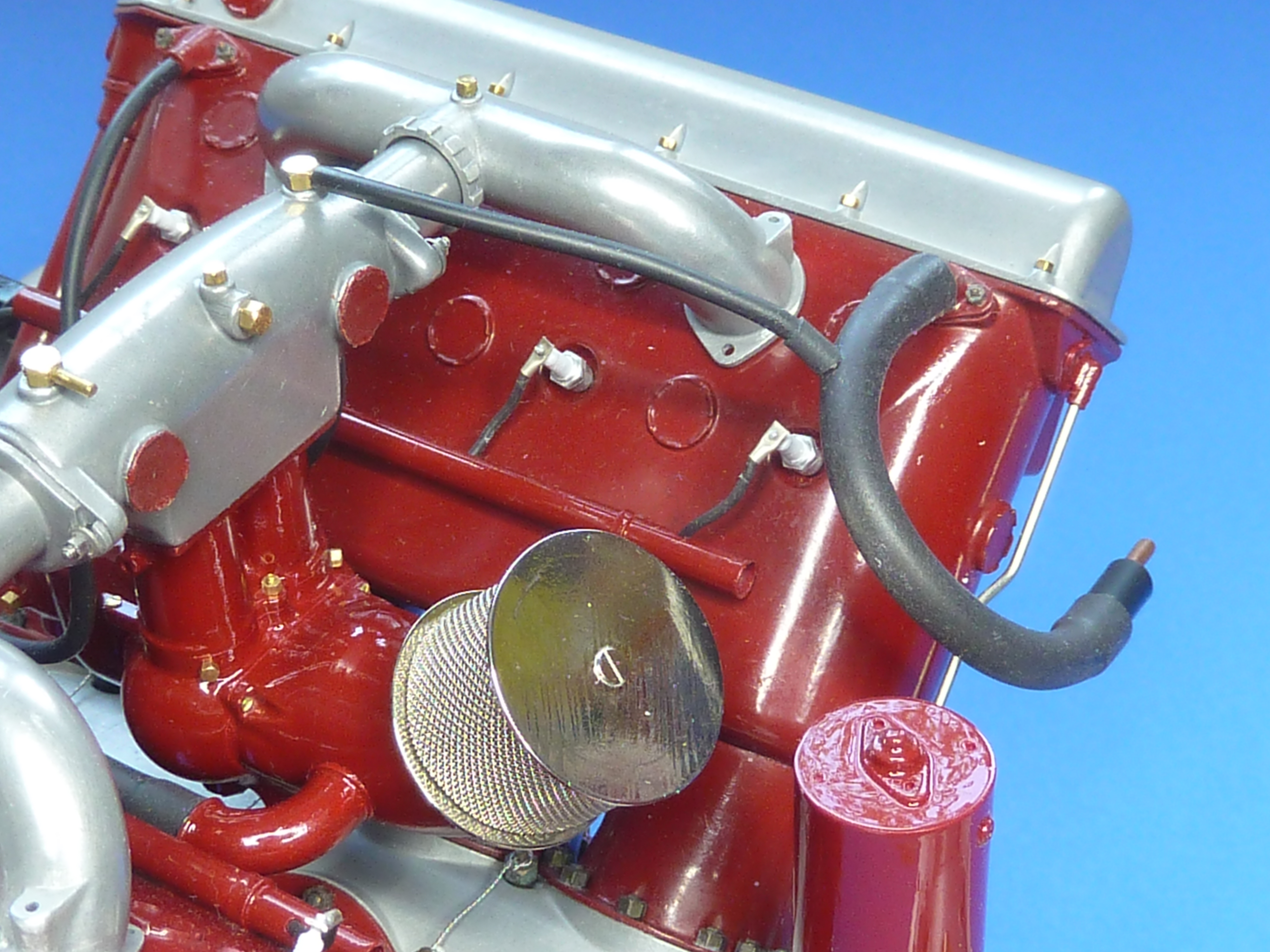
Here are a couple of pictures of the engine models as they stand at the moment.
I’ve continued to push on with the two Hispano-Suiza engines, but the burgundy coloured one is going in a slightly different direction to the black.
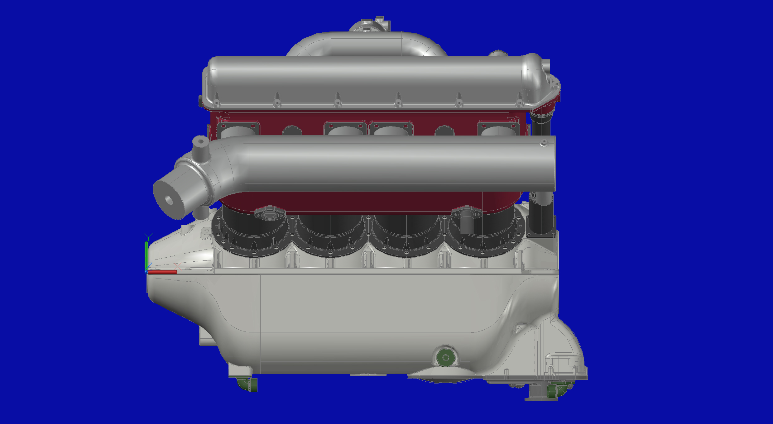
After adding both cylinder banks to it was time to look at the induction manifold.
Previously it had been a single piece casting which worked quite well, especially in pewter. It was very awkward to remove the more delicate cold cast resin part from the mould though. The one installed on the black engine did suffer a little damage that had to be repaired. The arrangement also has no adjustment within it, so getting the cylinders exactly the same height and at 90° to each other becomes critical to a decent fit. I wanted something that was a little more tolerant of minor errors.
The obvious solution was to divide the casting up in to 5 parts, as it is on the real engine. You quickly appreciate that the original designers must’ve done this to allow for manufacturing tolerances, amongst other reasons.
Hence a revised version was developed in CAD and sent off to be printed.
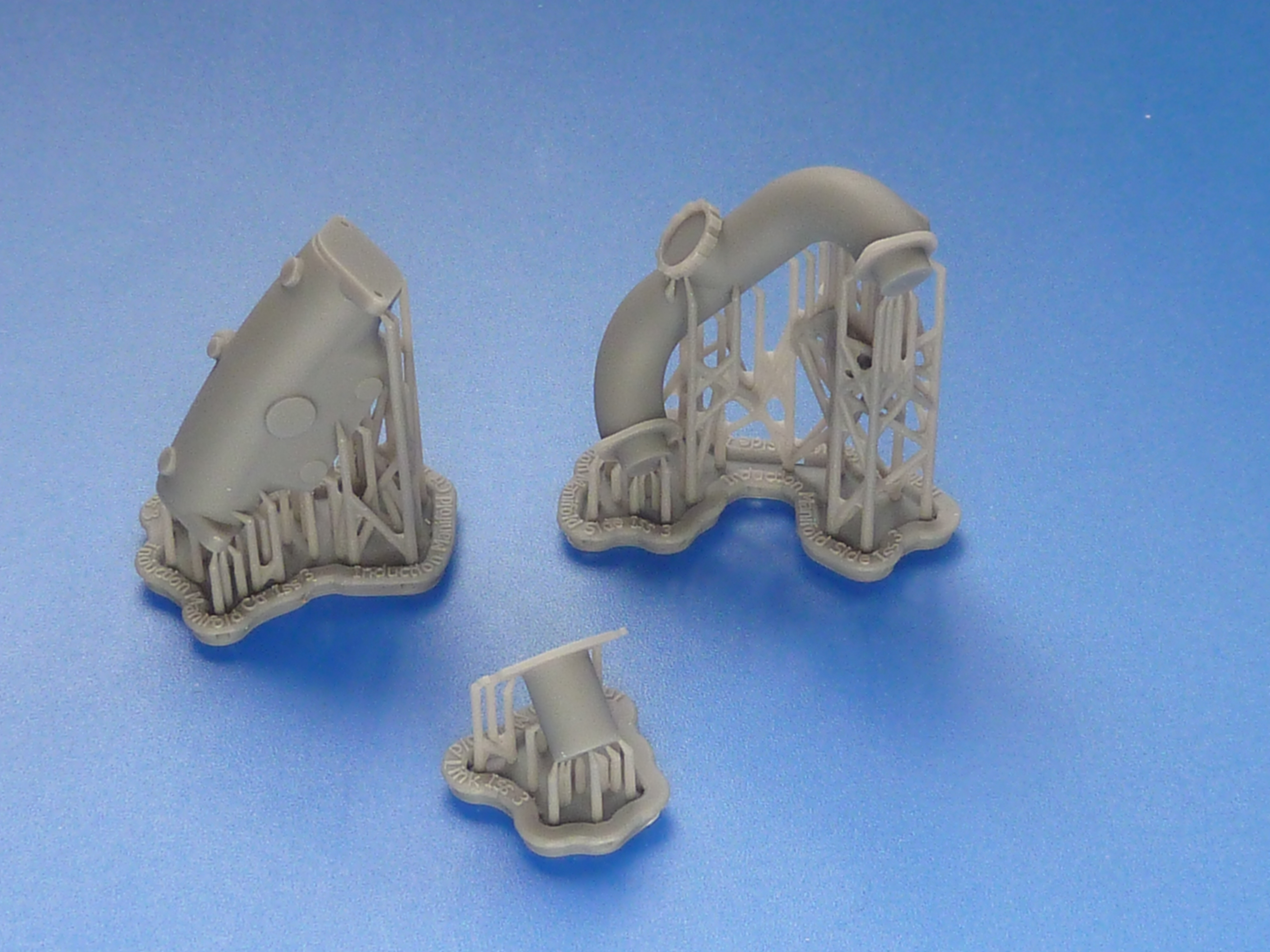
The revised parts fresh from the 3D print bureau with the print supports still attached.The parts after a quick clean up. The manifold is symmetrical about the centre, so I only need one side printing to make the mould for both.
The link piece in the centre of the picture above is deliberately slightly over length so that it can be trimmed to a perfect fit on the engine, giving me the slight adjustment I wanted.
The cold cast components. The left hand part has yet to be polished.
The link pieces were glued to the central casting and the outer parts dry assembled on the engine using 1 mm bolts to locate them accurately. Then commenced the trial-fettle-trial sequence making sure I reduced each link piece equally in length. During the process I also filed off the locating pegs on the bases of the side pieces because they were more trouble than they were worth to be honest.
The result is shown below, and a it is definitely better fit than previously, though there’s no actual visual difference between the two arrangements.
The parts can’t be permanently fitted though until the carb has been attached as well as the plugs, ignition leads and their guide tubes in the V.
Speaking of ignition systems brings me on to the main change on this model. The black engine retains the magneto ignition system of the aircraft engine. The full Auto Engine Works marine conversion changed this to a coil/distributor version with dynamo. This makes more sense in a boat where swinging the prop is problematic to say the least, and a starter motor with charging system almost essential.
I wanted to model this arrangement on the burgundy engine, so it was back to CAD to develop…
Once again a set of .STL files were created and emailed to the 3D print bureau and 3 or 4 days later the printed parts arrived in the post.
STL = STereoLithographic which was the process used in the earliest 3D printers. The processes have changed, but the file type has stuck.
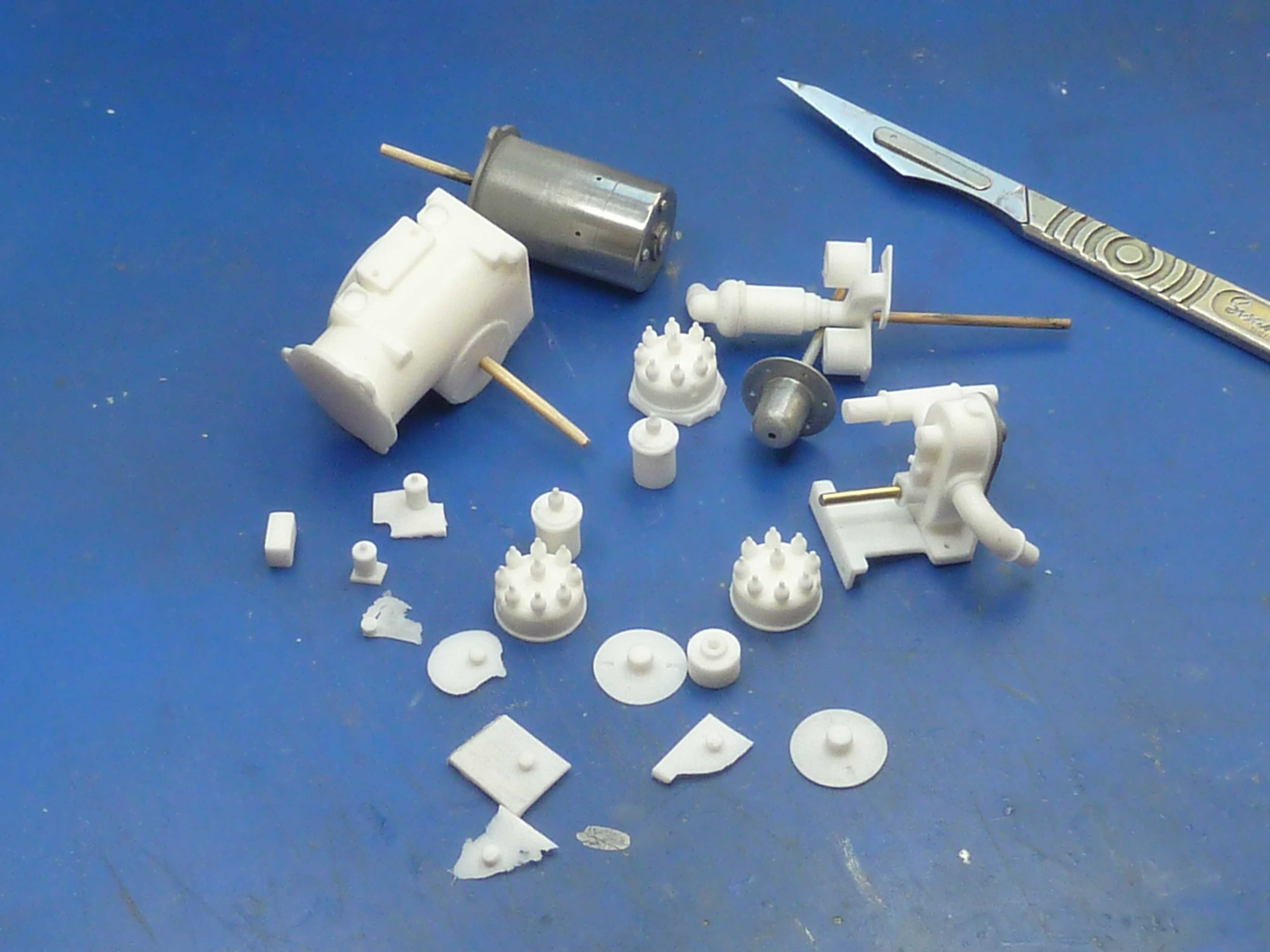
The parts with print support structure.And cleaned up ready to make moulds from.
Moulds were taken and the parts cast in polyurethane resin. The dynamo and front face of the water pump were cold cast because they would have bare ‘metal’ areas I wanted to highlight. Incidentally, exactly the same resin was used throughout. The only difference is that the cold cast items have 67%, by weight, aluminium powder added. The end housing was also cold cast simply because I had a little mixture left over after the other two, and it seemed a shame to waste it.
The parts cast in resin. The water pump has also been partially assembled in this picture and the bare metal part of the dynamo polished up.
The water pump faceplate came out quite well.
A quick bit of airbrushing later…
The black and silver components were sealed with a satin varnish.
The rest received a coat of burgundy gloss.
Once it had hardened I scraped back the faceplate of the water pump to highlight the company name.
The assembly also included a few photoetch components. The mask for them is shown on the right in the photo below. The large mask is for the exhaust system, including another drill template. I’ll come on to that saga in a future post.
The picture below shows it all assembled and mocked-up in-situ, but no plumbing or wiring has been installed yet. The pipe in the photo below is a trial fit, and I think it needs a smaller diameter one really. A bit inconvenient that, as the lugs are designed to take it. Guess which parts aren’t included in my CAD model…
The distributor assembly on the real engine includes a mechanical means of adjusting the timing advance. To replicate that it was back to CAD again. Then Photoshop to develop more etch masks. I cocked things up slightly on the latter. I forgot to add sprues to them and had to stop the etching process when it was 90% done and the components were still held together. Otherwise they would’ve fallen off the support and disappeared in to the bottom of the etch tank, never to be seen again.
Two sets of advance and retard mechanism components. The top are fresh from the etch tank. The bottom ones are after clean up.
After the residual flash had been removed the parts were stained and assembled using 0.7 mm brass pins as pivots.
I couldn’t resist mocking the whole thing up again on the rear of the model. It won’t be fitted permanently until I have sorted out the cooling pipe size issue and have installed the spark plugs etc. in the V of the engine, which will be the next job.
The advance and retard mechanism assembled and in place at the rear of the engine.
As an aside: I mentioned last month that I might put some mild weathering on one of the two engines, but wasn’t sure about the idea. To get an idea of how well it might work I carried out a trial on the scrap gearbox casting left over from when I dropped it.
Pre-weatheringPost weathering trial.
I’m reasonably happy with the result, but need to include a bit more gloss black in the mix to give a more oily appearance. Other than that I think it’s on.
It’s been decided that the black engine will be the standalone desk curio and the burgundy one will go in the Miss Severn boat model. Based on that it’s the black one which will get the weathering treatment.
It’s been almost 2 months since the last update, and in all honesty, despite a lot of effort over that period, there isn’t that much tangible to show for it.
A very quick update this time as there is very little to describe or show whilst building up the CAD model of the engine.
Things are going well, though the carburettor gave me some problems as it is all curved and blended shapes. Only the magnetos and marine conversion gearbox need to be added. All the bolts, cables and wires will be added during the actual assembly of the model. There’s no point 3D printing them as they won’t look right in the end.
I may even get around to building things in real life soon.