Tag Archives: model

‘MISS SEVERN’ 1922 GOLD CUP RACER – MACK MODELS 1:8 (PART 10)

I’m still not doing so well on the health front but have been able to make some progress on the Miss Severn model. It’s been a bit two steps forward and one back though.

I have at least finally got around to finishing off the deck fittings.

The cutwater needed several goes at plating to get a satisfactory finish, but we got there in the end.

I’ve also plated the chocks. Only the fairleads remain.

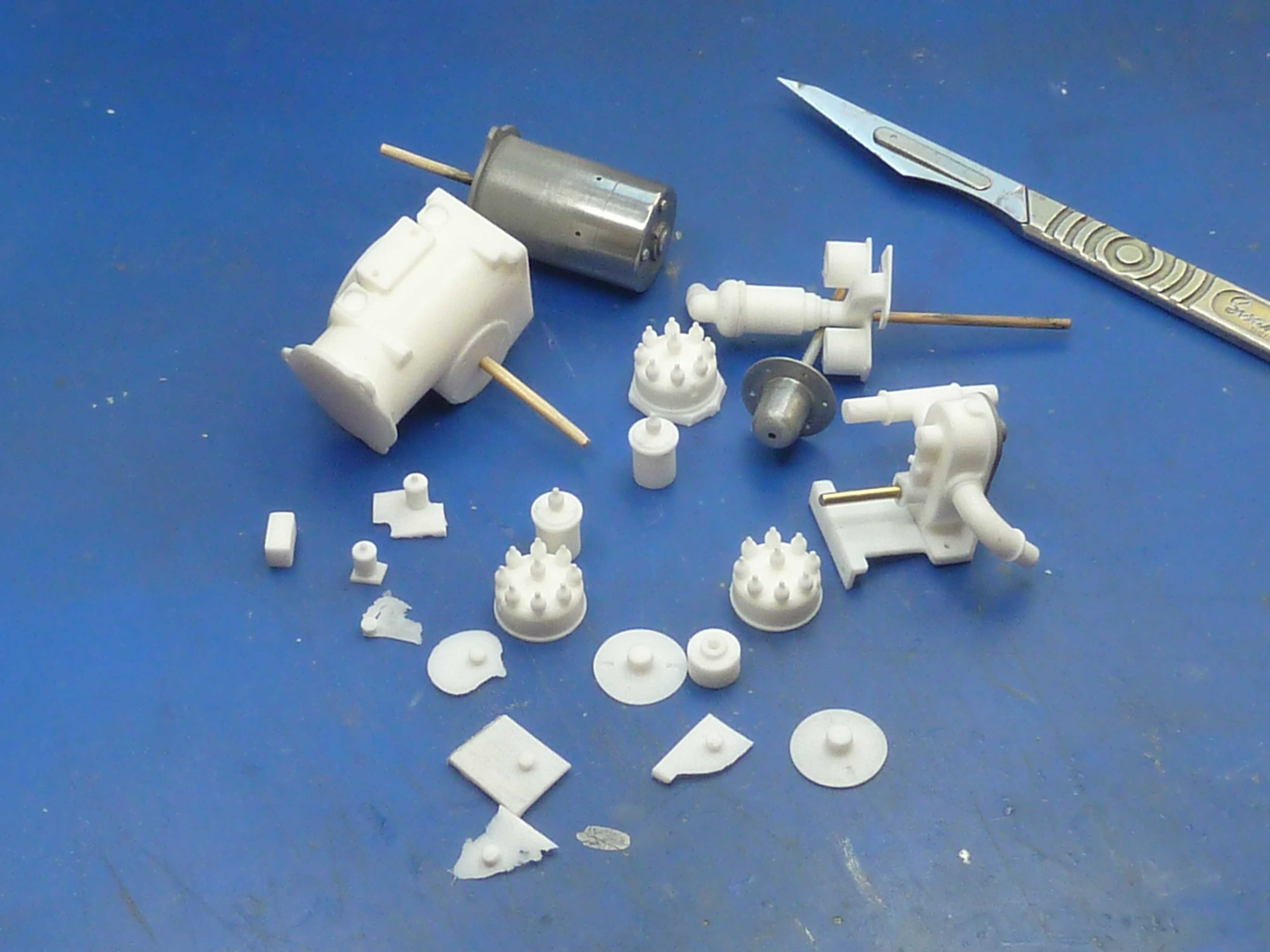
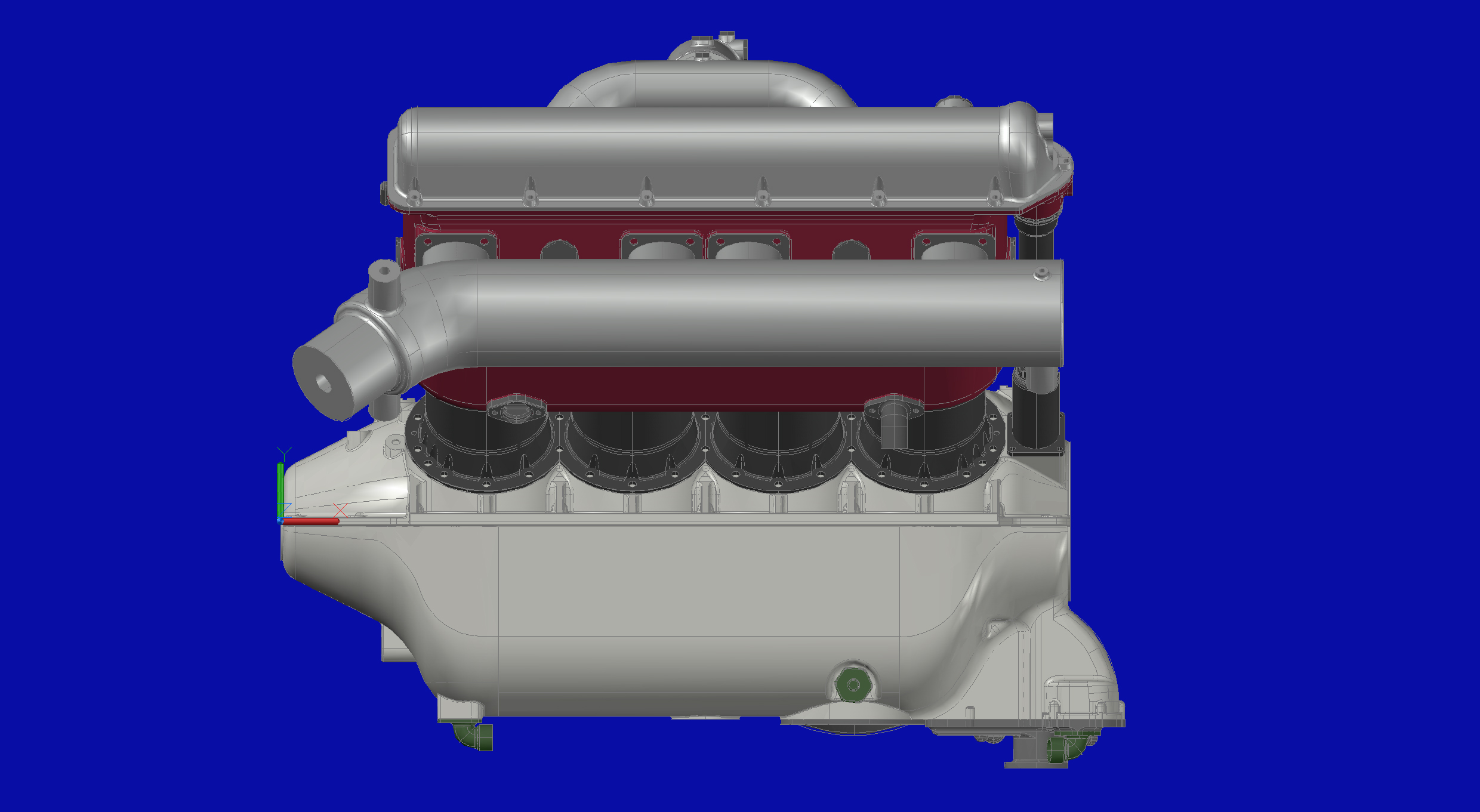
As all of the trial fitting of components in the engine bay is pretty well done I decided to refresh the paint for the final finish. Unfortunately there was a problem…

I thought I’d finished the rear bulkhead of the bay with epoxy resin so was a bit cavalier in my paint choice because epoxy doesn’t care too much. however, I’d forgotten that I’d actually used polyurethane varnish and this reacts badly to cellulose paint.

I was really quite vexed at this point. You know, REALLY vexed and quite upset.

So there then commenced a fun session of sanding down and removing all of the offending mess. After several sessions, of sanding and recoating I finally got back to where I should’ve been all along.

It’s still not as sharp as I’d hoped though.

The next step was priming the hull. No matter how closely you inspect the finish the grey primer always seems to reveal a smattering of defects and blemishes that you’ve somehow managed to miss. So there was a general sanding and filling of pinholes.

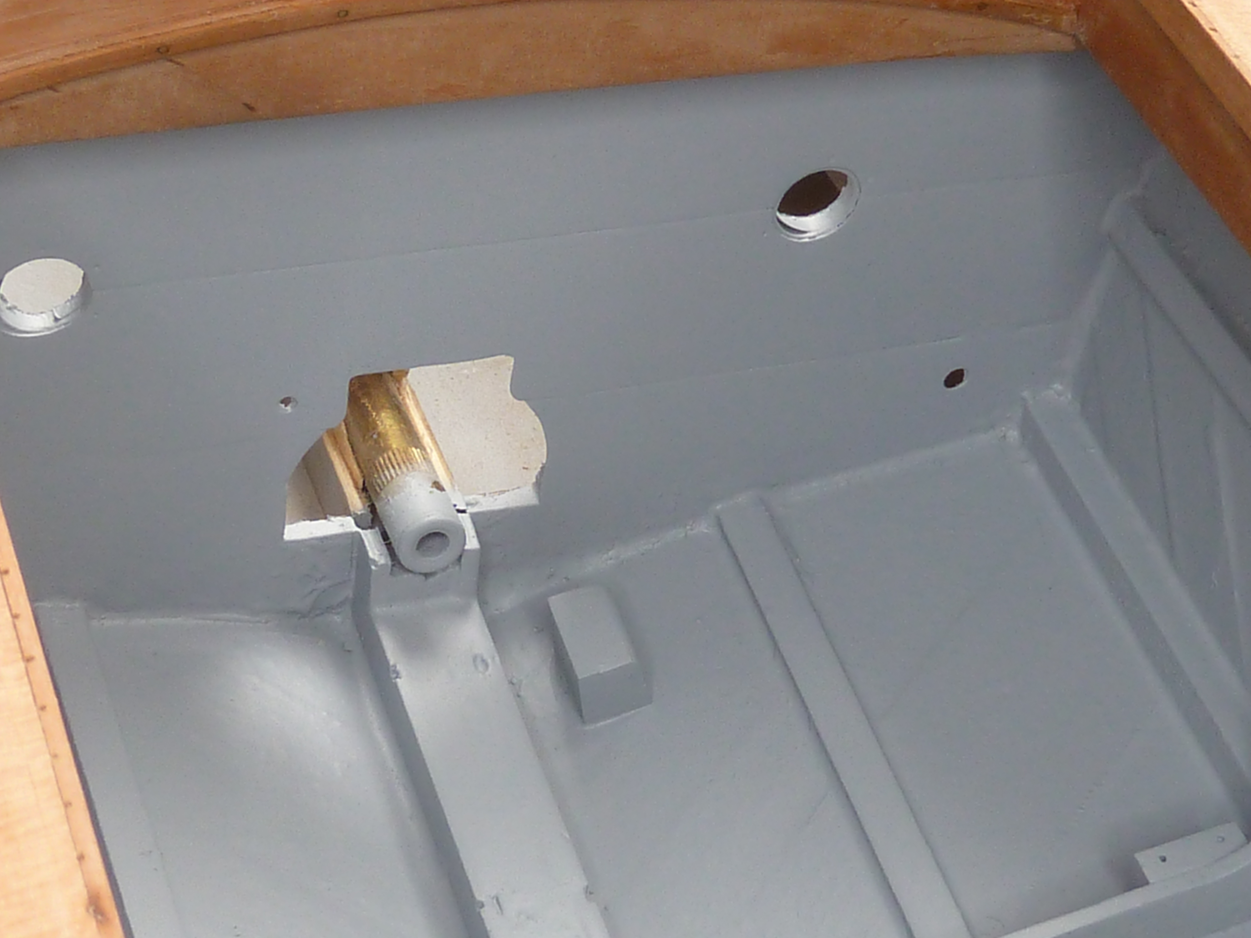
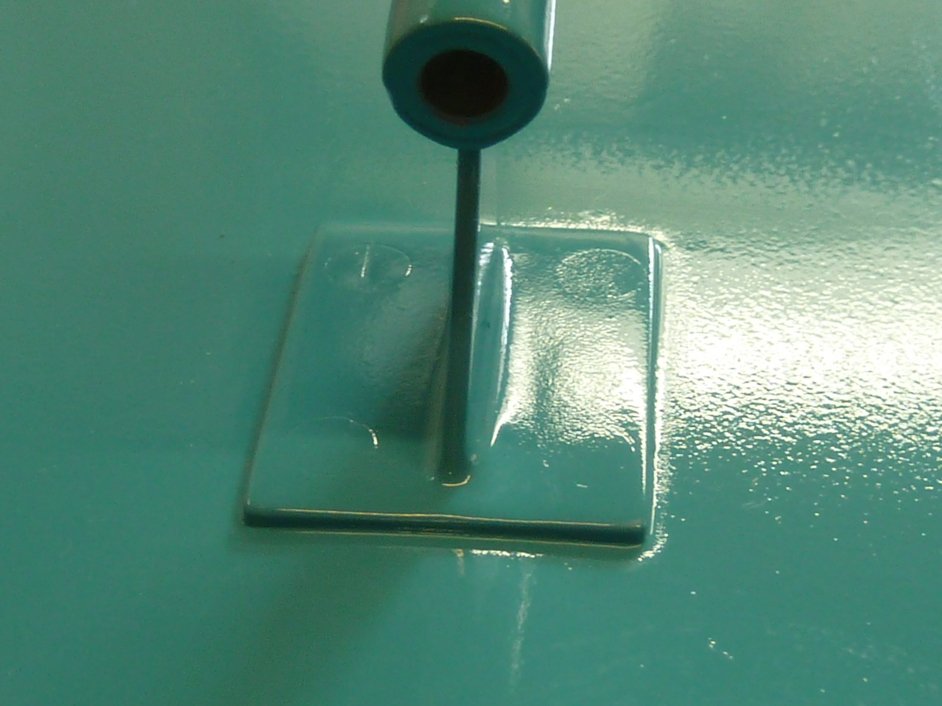
I had intended that the strut for the propshaft would be polished brass, but when I offered it up to the boat it looked too toy like, Hence I decided to paint it the hull colour after all. Also, somewhere along the line of resin coats and sanding, the small flat island I carved out for the strut’s base had been lost and needed restoring.

The masking tape is there to mark the outline of the strut and also to protect the surrounding paint while I filed away.
The rod in the bearing is there purely as a paint mask.

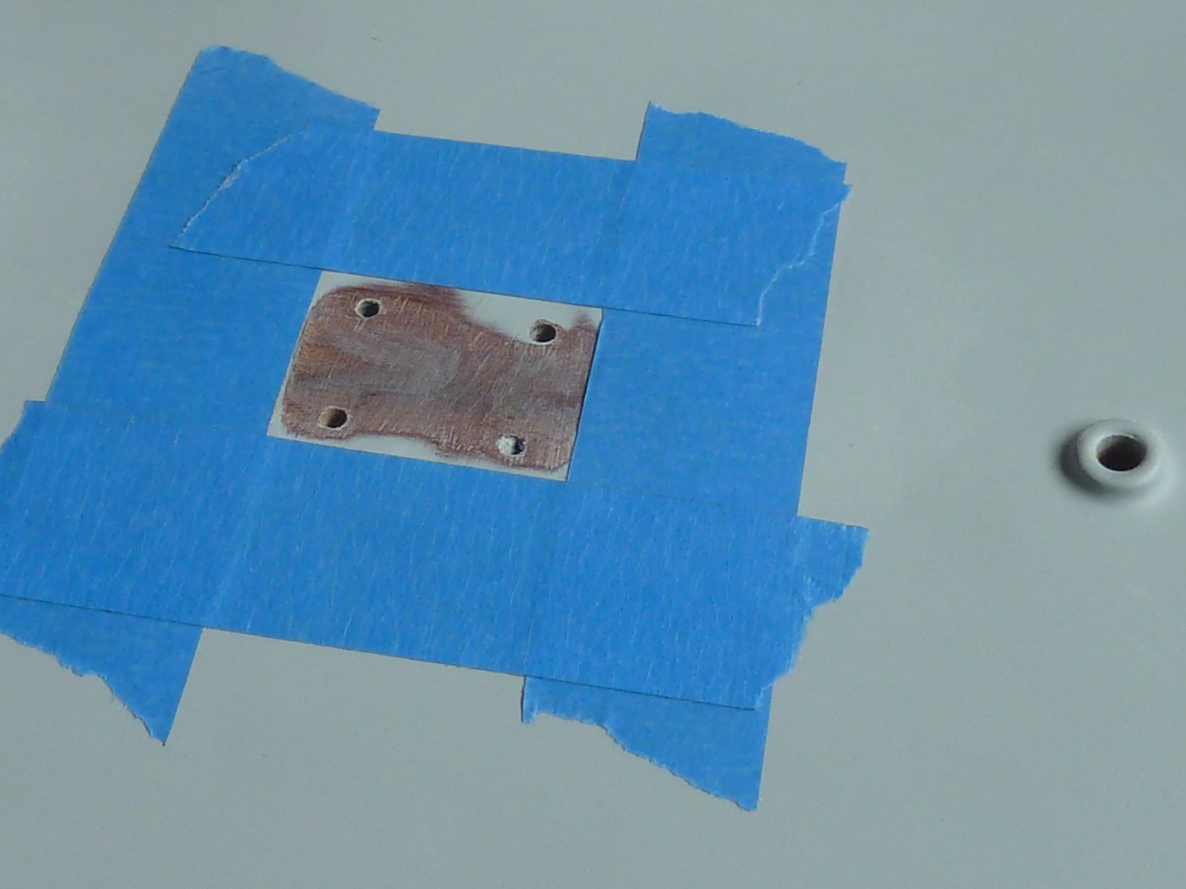
The strut comes ready drilled in the kit which wasn’t ideal for me. I did enquire whether it was possible to get an undrilled one but that is how Mack Models receive them. I didn’t want 4 totally out of scale rounded headed screws showing, so counter sunk the holes and used countersunk screws to hide them. Once they were sanded flat the gaps were filled with body putty and that sanded level. The strut is also glued in place using epoxy resin. Just enough to squeeze out the edges and fill any remaining gaps. I fitted the strut before I removed the masking tape in the previous pictures which made cleaning up the excess epoxy very simple. Pull off the tape before the glue is set and you’re left with a nice clean edge that self smooths.

Despite all the prep, the screws are still slightly visible when you get the light at the right angle. I’ve had this before and remain convinced that the filler shrinks very slightly over the days after the instructions tell you it is fully ‘cured’. Hopefully I can remedy that later.

The orange peel finish is due to the use of rattle cans for the paint, but will disappear once the varnish coats are applied.

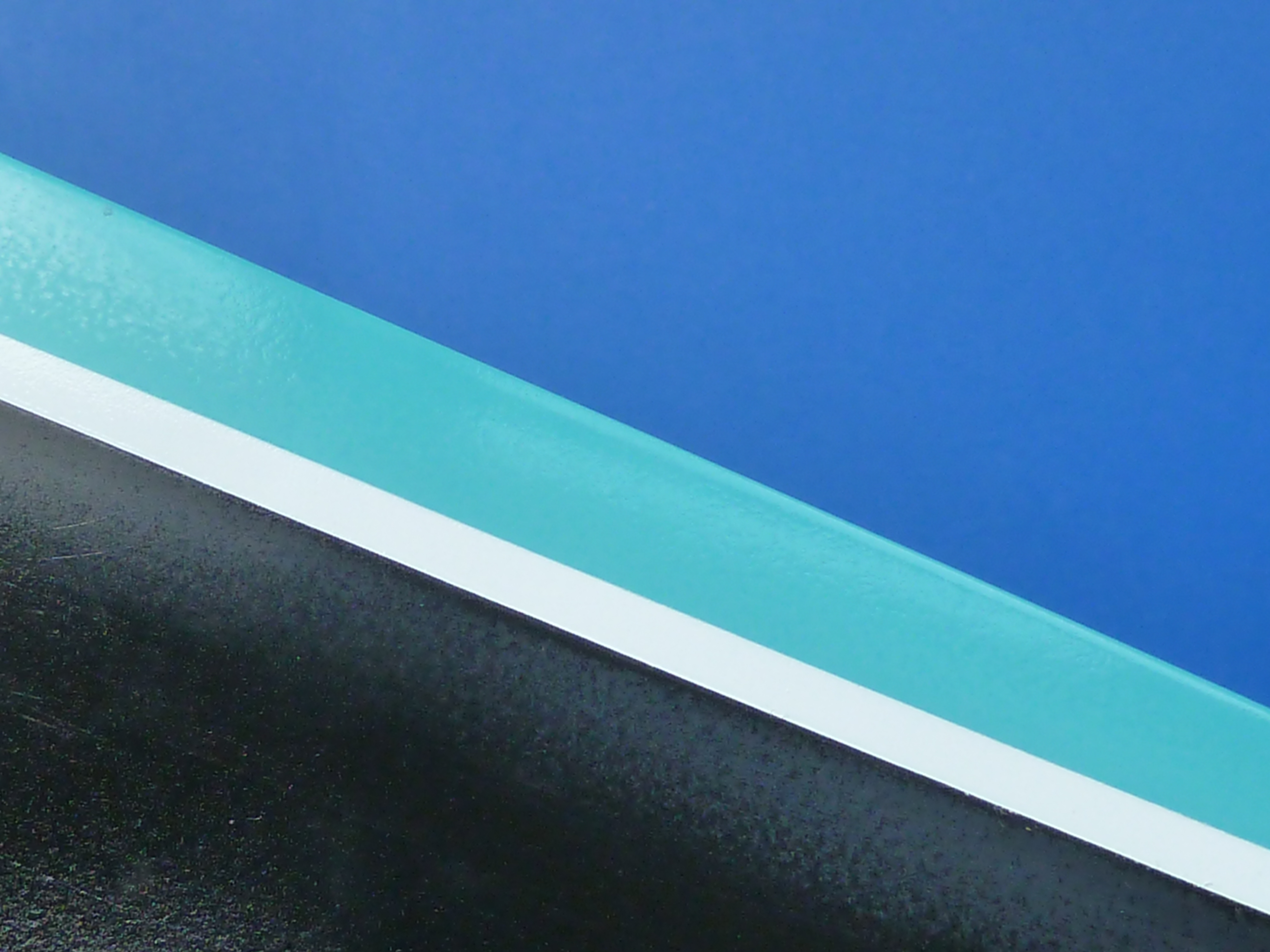
Having sorted the primer coat and the strut, I finally got around to throwing some paint at the hull. The first attempt went badly. I painted the waterline then masked it off to paint the aquamarine colour. Despite making a test piece, which went fine, the blue reacted with the white paint yet again. To say I was annoyed would be an understatement. I like to think I have some idea of what I’m doing when building models now, but to make a beginners error, twice in quick succession, rather questions that. What was especially annoying was that I made the test piece specifically because I was concerned about the problem as I was mixing paint from different manufacturers and that went perfectly.

There are no pictures of the mess as I was too annoyed to take them. In fact I walked away from the whole thing for a few days to calm down.

A less than enjoyable day was spent sanding all of the mess off, cleaning up and re-priming before a second attempt at painting , with paints all from the same manufacturer (Tamiya), which went OK.

I was using rattle cans for the main areas as the area is a little large for my airbrushes, and modelling desk. They didn’t give me a very sharp water line, so I re-masked that, decanted some of the white paint out of the can and applied it with my airbrush which gave a much sharper result.

Next up will be the staining of the woodwork. The transom is already done. However, I think I will apply a coat of varnish to the hull bottom and sides before I start mucking about with the decks. It’ll protect the paint a little, as it is still quite soft.

In parallel with all of the above I’ve been investigating methods for producing decent gold lettering for the boat name and registration numbers. I’d like them to be a convincing gold, and real gold if at all possible.

I mentioned briefly in an earlier post that I’d been messing about with gold leaf and even done some trials.

The Miss Severn lettering on the cutting mat was a trial of gold leaf application. It’s a mess because I also tested to see how easy it is to remove. (Ans: It isn’t. You get one shot.)

The results of the trials were OK, but not fabulous by any means. However, I did learn that:

        1.  I need a lot more practise to become any good at gold leaf application.
        2.  Gold leaf is more pervasive than glitter.
        3.  I’m not stellar at hand cutting letter masks.

Based on the above, especially the glitter bit, I’ve decided not to let gold leaf anywhere near the lovely black hull this time around. As a result I’ve been investigating other options. In particular I’ve been lusting after a vinyl cutting machine to allow me to produce decent complex paint masks for several years now, and have finally taken the plunge and bought myself a Silhouette Cameo 4 which is thoroughly living up to expectations.

It has already enabled me to cut some decent masks from thin vinyl.

The scalpel is there just for scale. It had nothing to do with the cutting.

Small islands in the text still need a lot of care such as those in the ‘A’s of Annapolis and they are about the limit of what the Cameo 4 will do I think.

By the way, Miss Sally is what the boat is going to be called now, not Miss Severn. The model is quite a way from a replica of Miss Severn at this stage anyway, and it personalises it too.

I’ve also experimented with using the machine to cut gold vinyl.

The top lettering has been airbrushed with gold paint using the mask in the previous picture. The lower lettering is cut from self adhesive gold vinyl foil.

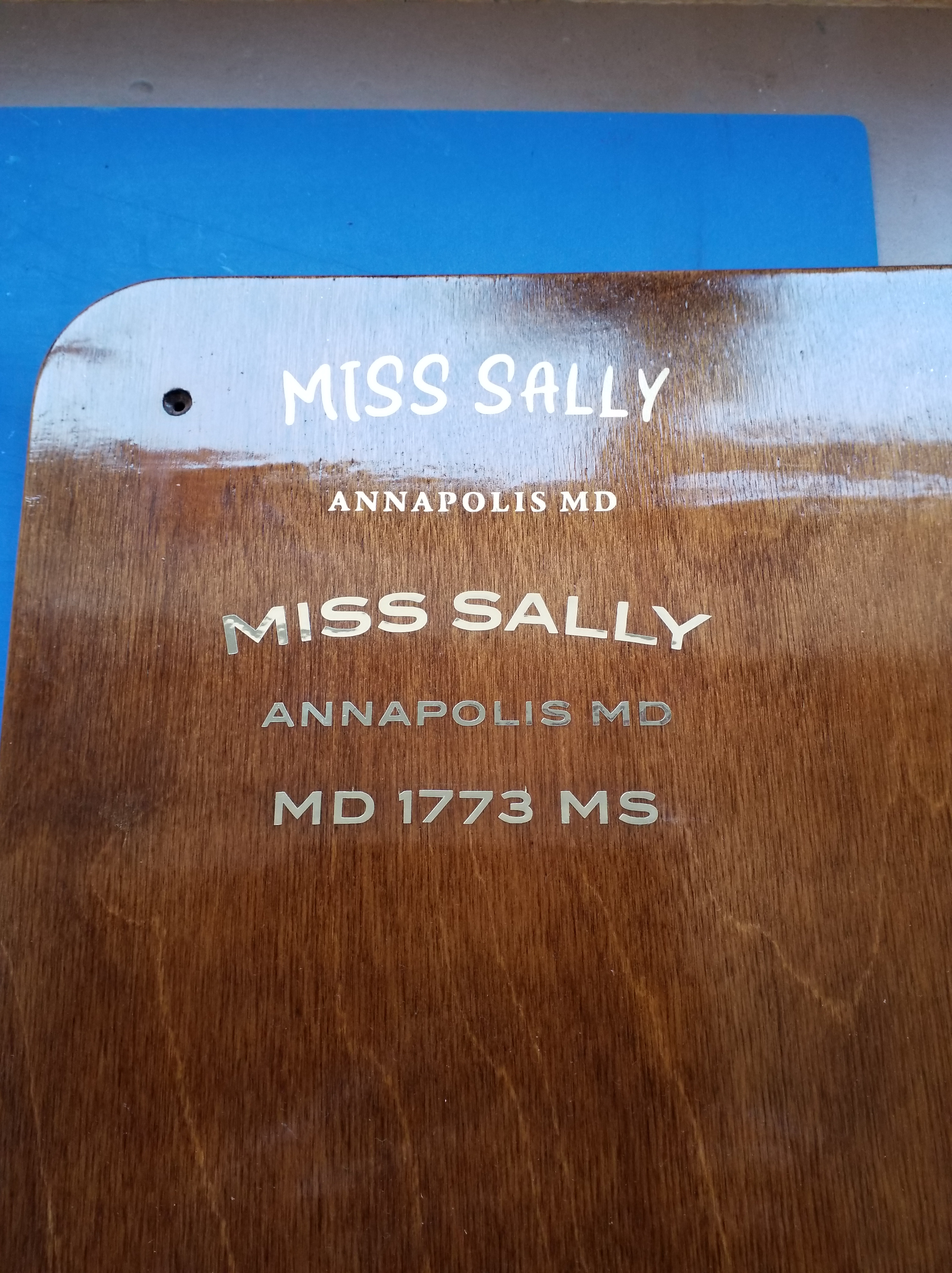
The vinyl foil I used was billed as being 23 microns thick, but my micrometer tells me it is 85 microns including the adhesive. That’s a bit thick to hide under varnish easily. It would take a lot of coats to hide the edges. Hence I’m still trying to locate some real gold self-adhesive foil, like the material they use for shop window lettering. That is billed as being 2-3 microns thick, and having looked closely at the lettering on shop winds in the past I can believe it. I can get small amounts of it from the US, and vast amounts locally for silly money. I haven’t as yet found someone in the UK that will sell me a meter or so of the stuff to play with. The search goes on…

Hispano-Suiza 8F (Part 8)

I’ve continued to push on with the two Hispano-Suiza engines, but the burgundy coloured one is going in a slightly different direction to the black.

After adding both cylinder banks to it was time to look at the induction manifold.

Previously it had been a single piece casting which worked quite well, especially in pewter. It was very awkward to remove the more delicate cold cast resin part from the mould though. The one installed on the black engine did suffer a little damage that had to be repaired. The arrangement also has no adjustment within it, so getting the cylinders exactly the same height and at 90° to each other becomes critical to a decent fit. I wanted something that was a little more tolerant of minor errors.

The obvious solution was to divide the casting up in to 5 parts, as it is on the real engine.  You quickly appreciate that the original designers must’ve done this to allow for manufacturing tolerances, amongst other reasons.

Hence a revised version was developed in CAD and sent off to be printed.

The revised parts fresh from the 3D print bureau with the print supports still attached.
The parts after a quick clean up. The manifold is symmetrical about the centre, so I only need one side printing to make the mould for both.

The link piece in the centre of the picture above is deliberately slightly over length so that it can be trimmed to a perfect fit on the engine, giving me the slight adjustment I wanted.

The cold cast components. The left hand part has yet to be polished.

The link pieces were glued to the central casting and the outer parts dry assembled on the engine using 1 mm bolts to locate them accurately. Then commenced the trial-fettle-trial sequence making sure I reduced each link piece equally in length. During the process I also filed off the locating pegs on the bases of the side pieces because they were more trouble than they were worth to be honest.

The result is shown below, and a it is definitely better fit than previously, though there’s no actual visual difference between the two arrangements.

The parts can’t be permanently fitted though until the carb has been attached as well as the plugs, ignition leads and their guide tubes in the V.

Speaking of ignition systems brings me on to the main change on this model. The black engine retains the magneto ignition system of the aircraft engine. The full Auto Engine Works marine conversion changed this to a coil/distributor version with dynamo. This makes more sense in a boat where swinging the prop is problematic to say the least, and a starter motor with charging system almost essential.

I wanted to model this arrangement on the burgundy engine, so it was back to CAD to develop…

Once again a set of .STL files were created and emailed to the 3D print bureau and 3 or 4 days later the printed parts arrived in the post.

STL = STereoLithographic which was the process used in the earliest 3D printers. The processes have changed, but the file type has stuck.

The parts with print support structure.
And cleaned up ready to make moulds from.

Moulds were taken and the parts cast in polyurethane resin. The dynamo and front face of the water pump were cold cast because they would have bare ‘metal’ areas I wanted to highlight. Incidentally,  exactly the same resin was used throughout. The only difference is that the cold cast items have 67%, by weight, aluminium powder added. The end housing was also cold cast simply because I had a little mixture left over after the other two, and it seemed a shame to waste it.

The parts cast in resin. The water pump has also been partially assembled in this picture and the bare metal part of the dynamo polished up.

The water pump faceplate came out quite well.

A quick bit of airbrushing later…

The black and silver components were sealed with a satin varnish.

The rest received a coat of burgundy gloss.

Once it had hardened I scraped back the faceplate of the water pump to highlight the company name.

The assembly also included a few photoetch components. The mask for them is shown on the right in the photo below. The large mask is for the exhaust system, including another drill template. I’ll come on to that saga in a future post.

The picture below shows it all assembled and mocked-up in-situ, but no plumbing or wiring has been installed yet. The pipe in the photo below is a trial fit, and I think it needs a smaller diameter one really. A bit inconvenient that, as the lugs are designed to take it. Guess which parts aren’t included in my CAD model…

The distributor assembly on the real engine includes a mechanical means of adjusting the timing advance. To replicate that it was back to CAD again. Then Photoshop to develop more etch masks. I cocked things up slightly on the latter. I forgot to add sprues to them and had to stop the etching process when it was 90% done and the components were still held together. Otherwise they would’ve fallen off the support and disappeared in to the bottom of the etch tank, never to be seen again. 

Two sets of advance and retard mechanism components. The top are fresh from the etch tank. The bottom ones are after clean up.

After the residual flash had been removed the parts were stained and assembled using 0.7 mm brass pins as pivots.

I couldn’t resist mocking the whole thing up again on the rear of the model. It won’t be fitted permanently until I have sorted out the cooling pipe size issue and have installed the spark plugs etc. in the V of the engine, which will be the next job.

The advance and retard mechanism assembled and in place at the rear of the engine.

As an aside: I mentioned last month that I might put some mild weathering on one of the two engines,  but wasn’t sure about the idea. To get an idea of how well it might work I carried out a trial on the scrap gearbox casting left over from when I dropped it.

Pre-weathering
Post weathering trial.


I’m reasonably happy with the result,  but need to include a bit more gloss black in the mix to give a more oily appearance. Other than that I think it’s on.

It’s been decided that the black engine will be the standalone desk curio and the burgundy one will go in the Miss Severn boat model. Based on that it’s the black one which will get the weathering treatment.

Hispano-Suiza 8F (Part 2)

A very quick update this time as there is very little to describe or show whilst building up the CAD model of the engine.

Things are going well, though the carburettor gave me some problems as it is all curved and blended shapes. Only the magnetos and marine conversion gearbox need to be added. All the bolts, cables and wires will be added during the actual assembly of the model. There’s no point 3D printing them as they won’t look right in the end.

I may even get around to building things in real life soon.


Chris Craft 19ft 1940 Barrel Back – Dumas 1:8 (Part 6)

It’s past time for another post about the Chris Craft build. This activity was always intended as one to learn the new techniques required for marine models on. Because of that, it is effectively  pacing the Miss Severn build, and only getting attention when I need to practise or prototype something for that primary project. Continue reading Chris Craft 19ft 1940 Barrel Back – Dumas 1:8 (Part 6)