
Preamble Gubbins
This post is aimed at people who have little knowledge of model making but I hope will also be of interest to more experienced modellers. For the latter, please bear with me through the bits where I’m talking about the basics and teaching you to suck eggs.
The Main Bit
I’d fancied building an F-4 for a while as it is probably my favourite aircraft. I already have a model of the RAF’s FGR.2 (F-4M in McD speak) in the loft so I thought I’d build a US variant this time. As a friend flew them operationally in Vietnam, and Tamiya do some nice large F-4D and E kits, I thought I’d build an airframe he actually flew.
After a brief enquiry, my friend loaned me a copy of USAF F-4 Phantom II MiG Killers 1972-73 annotated to show some of the aircraft he’d operated in. A quick bit of research revealed that one of these aircraft, tail no. 463, was actually quite famous as it had been involved in 6 MiG kills in the hands of several crews between 1st March and 15th October’72, but most notably Capt. Steve Ritchie and Capt. Chuck (Froggie) DeBellevue. The aircraft was based at Udorn RTAB in Northern Thailand and was part of the 555th/432nd TRW.
The aircraft was originally built in St. Louis in 1966 and delivered new to 479th TFW on 28th Jan 1967. It then went through a succession of squadrons before beginning its notable combat career with the 432nd TRW on 4th January 1972. The aircraft was eventually retired from active service in October 1986 and is now on display at the USAF Academy in Colorado Springs.
Here is the actual aircraft, serial number 66-7463, in a revetment at Udorn around Sep/Oct 1972.

Having searched the net and various books one thing that did surprise me was how often this aircraft got repainted. Almost every picture is different in detail when you begin to analyse them. The number of MiG kill stars being the obvious one, but also the actual camouflage patterns and placement of crew names, unit patches etc. The situation is further complicated from a research point of view by another aircraft that has been painted to look like 463 and appears at airshows in the USA. In the end I decided to paint it as it appeared at the end of the conflict, but even then I had to guess some details.
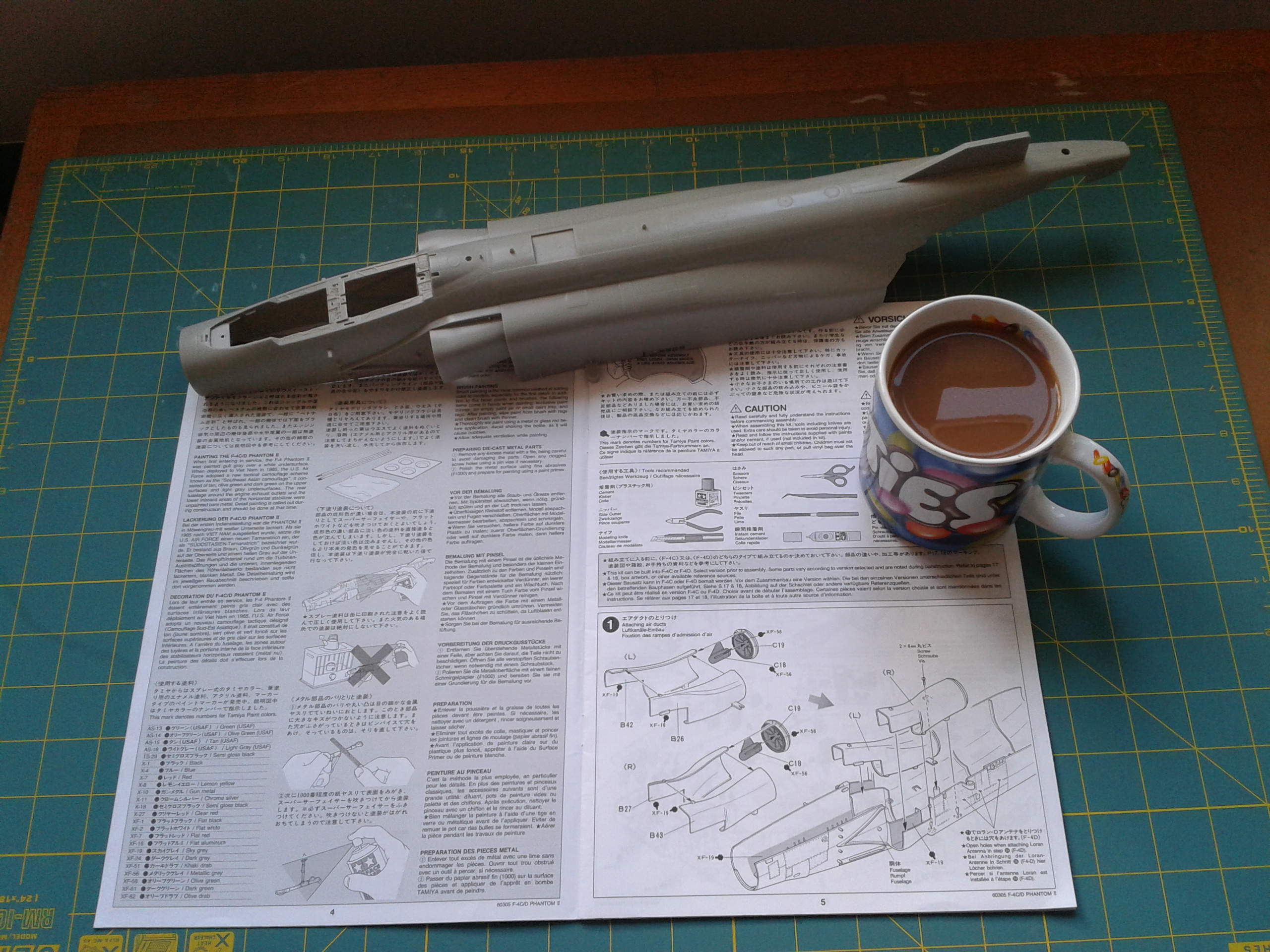
The main component of the model was the Tamiya kit, obviously, shown here with some suitable reference books…

and this is what you get inside the box, plus that lovely fresh kit smell.

The basic model is pretty good but has a number of known ‘errors’ which need to be corrected including a fairly unforgivable fault with the fit of the intakes. Most of the ‘errors’ are due to Japanese thoroughness in copying the original aircraft I’m told. As the design aged in service a number of strengthening patches were added to overcome local fatigue problems and also other mods. Tamiya have copied them all faithfully. This is less than ideal because most of them were incorporated post Vietnam so wouldn’t have been on the aircraft at the time I wanted the model to represent so they would need to be removed.
In order to increase the amount of detail in the model I also used a BigEd omnibus set of Eduard’s add-on F-4D/E photoetched detail sets which are specifically designed for the Tamiya kit. These are thin sheets of nickel plated brass into which have been etched detailed parts, and some pre-painted. The level of detail that they can achieve on these is amazing, but they are extremely fiddly and it takes a while before you get comfortable with them. Prior to that they can induce a fairly thick blue fug of expletives around the work area if you are that way inclined, and even if you’re not.


Pre-printed main instrument panels are shown on the left (which feel like a bit of a cheat but no more than using decals really) and raw unformed or painted ejection seat parts on the right.
The other key ingredient was the aircraft’s decals. Tamiya’s own are good as far as they go, but they omit many of the detailed aircraft markings and obviously don’t cover ‘463’s specific markings. To improve the detail I bought an additional set of panel detail decals from Icarus which actually covered the F-4E, but the majority are shared with the D and would be OK. I experimented at generating masks to allow me to airbrush the 463 tail numbers and such, but while I was developing the techniques to get them as sharp as I wanted I found a company that actually sold an add-on set for 463. Job jobbed, or so I thought.
With all the bits to hand and research done I could actually start building.
The main tools that I use for modelling are shown in the picture below. An Iwata HP-C airbrush, a couple of different shaped scalpels, tweezers, warded needle files, emery sticks and lots of paint brushes. There are a lot of other items in the tool box for specific jobs and some specialist tools for working with photoetch.

The paints I use are a mixture of good old Humbrol enamels and Tamiya acrylics. The reason for the two types is that as they have different solvent bases (naptha and alcohol respectively) you can paint one type on top of the other without them mixing. The artists oils in the tool box are for delicate shading and blending jobs as they remain workable for hours and don’t dry up on you. All large areas are airbrushed and detail is done by paintbrush.

The colours reflect the fact that a lot of my models are military, so greens, browns and greys predominate.
The basic assembly techniques are straightforward and familiar to anyone who’s messed about with models, though I do use a very thin poly cement which you paint on with a fine paintbrush rather than squeeze out of a tube. The stuff is the thickness of thinners so you can be very accurate. It will also wick down small cracks which can be invaluable in applying it invisibly. The one downside I have found is that it shrinks as it dries out. So you need to leave it 24 hours before sanding down any joints or your invisible seam will reveal itself later.
Photoetched parts are glued with superglue, but again I use a special thin type. I also have some Zip Kicker from Zap Glue which is a chemical that makes superglue truly set instantly and fully cure which is very useful. Beware though, it really does do what it says. It’ll set the stuff on your applicator too and make the contents of the bottle go thick and gooey if you put the applicator back in the bottle.
To apply the superglue I usually use a thin piece of wire held in tweezers. You can accurately control the amount being applied and the location and it ensures the main bottle stays uncontaminated with anything. Just wipe the glue brush on the wire to deposit a blob the size you want, then dab it on where you need it.

That’s it for the basic prep and tools. Now actually building the model.
The basics of the build were not actually much different from any other plastic kit to be honest. You start with the smaller sub-assemblies and gradually work your way up to the main airframe. There’s just a lot more of it and a fair bit of fiddling with photoetch (PE) add-ons.
The one thing that might differ from what non-modellers expect is that none of the parts are painted before they are removed from the sprues, which how I was taught to do it “when I were a lad”. Instead the first task is to remove the parts of the next bit to be assembled and clean up any flash or lines where the mould joins are. Marks left by the ejector pins, which push the newly cast sprue out of the mould, also need to be addressed and any sink holes caused by the plastic contracting as it cools. Tamiya are good on the last two and generally their kits are designed so that ejection pin marks are out of sight on the assembled model and sink holes don’t occur. Cheaper kits aren’t so good on this front.
The picture below shows some ejector pins marks (raised circles in this case, though they can also be sunken) in the cockpit area of the Airfix 1:24 Mosquito. These will need to scraped off and sanded smooth if they are visible. In fact the kit is covered in them and will require a fair bit of patience to sort out. “Dearest Airfix, a word, if you please….”

In the first part of the assembly process I focussed on the cockpits, as is the way of most aircraft models, though the Tamiya instructions for this kit get you going on the main intakes first. However, because I knew they would be problematical I wimped out and left them until later. The other thing was that the Eduard cockpit photoetch stuff looked so good I couldn’t wait to play with it.
The initial steps are exactly as per the instructions which I have binned now so I can’t show you specific pics. (sighs of relief in the back row). However, here’s one I took earlier with essential modelling materials shown…(low groan from back row).
I have honed most of my modelling techniques making armoured vehicles where the preference is to assemble as much as possible before painting to avoid join lines and any glue marks. It’s something I carry over into my other builds so I tend to assemble more than is usual before I paint. Thus the basic structure of the cockpits and panels were all put in place, the PE detailing added in the footwells etc, but not the instrument panels. Then the whole thing was airbrushed in the light grey of the Phantom cockpit.

After it had been allowed to harden for a few days the basic cockpit LRUs (Line Replaceable Units) were blocked out in black, with regular references to pictures off the net. The preprinted main instrument panels were also added at this stage. These are a sandwich of 2 parts (instrument facia and dial faces) which need careful alignment during assembly. I found that the background grey colour used by Eduard was noticeably different from the Humbrol grey I had used. As a result of this I ended up going over the Eduard grey by hand very carefully so that they matched the rest of the cockpit.

The next job was to assemble the seats. I don’t have pics of this and frankly I’d rather forget the whole episode. They involved a lot of PE and detailed shading work with oils and stuff. Oh, and a few decals to add to the fun.
Picture our hero peering through his magnifier for days on end with intermittent heavy sighs, the odd verbal encouragement to recalcitrant parts and very rarely “Yes! He shoots, he scores!”
The paint on the cockpits had hardened (and was probably well on the way to yellowing) by the time I had finished the seats, so I was able to apply what’s known as a wash. This is oil paint very thinly diluted with turps until it is a mere tincture of its former self. I use turps because it is less aggressive than enamel thinners, so less likely to affect the existing paint before it evaporates. For this wash I used ‘burnt umber’ which is obviously a posh dark brown.
Applying a wash gives a slight tint to the surfaces and the pigment, by happy coincidence and surface tension, collects more around raised or sunken features accentuating them slightly. It nicely simulates the effect of general of grime and how it naturally collects in corners and the like. The effect needs to be subtle on an aircraft as they don’t get that dirty, (compared to tanks anyway). I use washes quite often and I’ll include more on the use of them when I cover painting the main airframe.
The results of the wash can be seen best in this picture of the rear cockpit. It’s perhaps slightly overdone, but the areas will be in deep shadow on the model so I accentuated it.
Before the wash…

Apres wash

Once that was done is was just a case of painting the details on the side consoles and adding the throttles. The throttles are a bit of an irritation as they are in the mid position. With the aircraft unoccupied, they should be fully aft, but by the time I realised, it was a bit late to change. Nobody will notice will they?
The end result of all this did have definite impact. It looked pretty good, even to me. The seats were only placed in position for these shots. they weren’t actually glued in place until the very end as they would have made masking the cockpit off for overall painting awkward.


Even so I don’t think the harness straps hang in quite a logical fashion, but it is difficult to work out what is happening on the real seats from pictures, and the Martin-Baker Mk.7 seats are quite different from the Mk.10 ones I have seen in real life, so I was flying a bit blind.
While I was doing the cockpit I also did the cockpit parts of the main fuselage in parallel, including adding the centre part of the canopy and upper rear instrument panel. This came with representative rears to the instruments but no wiring. A few locating holes drilled in the instruments and the addition of some copper filaments sorted that and was quite easy to do. Don’t try to trace the wires though. They just look right but have no logic, a bit like the slippery road sign used in the UK..


You will notice that I had also airbrushed and weathered the cockpit coamings by this stage. The scratched and worn look was achieved using what is known as ‘the hairspray technique’ which I’ll describe now, because it’s worth it.
The hairspray technique works by having a base layer of, say, silver to simulate the underlying metal, then a layer of hairspray (which is a weak acrylic lacquer really) and finally the main colour top coat. The hairspray doesn’t bind well to the bottom coat, especially metallics, so if you scratch the top coat gently with a knife it will flake off with the hairspray leaving the bright silver showing through. You can increase the effect by applying water too which dissolves the hairspray making the top coat come off in even bigger chunks.
Here is a sequence of photographs of the crew ladder showing how the effect is built up.
Bare plastic

Silver substrate

Hairspray with yellow top coat on top

Finished item with scratches applied.

So that was it for the front office and soft furnishings stuff. Here are a couple of pics of it all in place in the final model.


Next, the wings go on, the wheels go down and the ordnance, err, goes off?
Compared with the cockpit, and those damn seats especially, the construction of the engines, nozzles and intakes was relatively straightforward.
Engines is a bit of a misnomer really as the kit doesn’t actually have any. Instead at the front you just get the intakes with the first stage compressor, and at the rear, the nozzle and jet pipe with the afterburner assembly and final stage turbine in it. That’s all you can see on the real aircraft though, unless the bonnet’s up.
Here’s a pic of the bare components, excluding the intakes, which I’ll mention in a bit.

Assembly was simple. Even the photoetch afterburner ring detailing was OK, the hardest part being cleaning them up without bending the things.
To paint the components I used Humbrol’s Metal Cote paint. This is odd stuff and I’ve found it awkward to apply. It says you can paint it on by brush but on anything but the smallest pieces it looks awful and full of brush stroke lines. So airbrushing is a must, but even then I have continual problems with getting an even repeatable flow which may be down to my airbrush. I think it requires one with a larger nozzle than the one I have (0.3mm), but with persistence I can make it work.
The paint goes on like any other mettalic but dries looking matt and dull. However, and this is the exciting bit, once it’s dried you can buff it up with a soft cloth and it really does come up looking like the real thing. It’s a mile away from normal silver or gunmetal paint.
The compressors were sprayed overall with ‘Flat Aluminium’, masked off, and then the air starter fairing and outer body was sprayed with ‘Polished Steel’. This was then polished up to bring out the metal look. The whole thing was then sealed with a gloss acrylic varnish to protect it. To improve the look of the starter motors I then went over them with a 6B pencil to give them a good coat of graphite which I also buffed up to a nice shine. Finally a thin wash of black was applied to the compressor blades to pick out the details.
Unfortunately I forgot to take a pic of the compressors after I finished them so you’ll have to be satisfied with one just prior to the wash being applied.

The nozzles and afterburner assembles were sprayed with ‘Polished Steel’ again and buffed up with a soft toothbrush which allows you to get into the nooks and crannies. To enhance the detail inside the engines I also gave them a delicate ‘dry brushing’ with a very pale cream colour.
The colours of the interior of the jet pipes seem to vary widely in the various pics I’ve seen. I assume because it depends how much the jockey up front has been using the burners or something, so the light going over with cream was a cop-out compromise in the end.
Shiny cleaness

Sooty mess

By the way, dry brushing is an old technique which seems to be out of vogue in the mags now, but many still use it, especially older modellers. You load a soft brush with paint and then wipe virtually all of it off with a rag, leaving just enough on the bristles to make them damp. You then lightly brush this over the piece you are treating and it leaves a very small amount of paint on all of the raised parts of the surface. It’s a nice simple way of subtly enhancing detail. It’s unforgiving though. If you have any blemishes on the surface or bristle marks in the paint finish it will accentuate them too.
The finished items looked like this.

I was sort of happy with the nozzle assemblies at this stage and put them on one side. However, while I was checking the net for other details I came across quite a few other images of aircraft and decided to tweak what I done to make it a bit more interesting and a closer match to some of the pictures.
The nozzles were masked up again and the aft part painted with ‘Flat Aluminium’ which was a bit stark at first,

but after a coat of acrylic varnish to protect it (the finish of Metal Cote paint reacts hideously to any solvent), a wash with more posh brown and a final coat of matt varnish they were much better.
Le model

Le real thing

So that was the ‘engines’. It only left the intakes to be fitted.
Now this is a known problem area on this kit, but it wasn’t until I got it I realised how bad. It’s not so much a poor fit as nowhere near and the worst I’ve seen on a Tamiya kit. The intakes are OK in the way the install in the fuselage insomuch they don’t foul anything, but neither do they touch where they should. The front edges should blend in seamlessly with the leading edges of the intakes. They don’t. They don’t even try. They are about 3 or 4mm out, which is huge at this scale. In real life it would be a 5″ into wind step. Come on Tamiya, this isn’t a cheap kit. Pull your finger out and fix it.
This photo is taken from a ModelingMadness.com review of the kit where the builder constructed the model ‘out of the box’ with no corrections or additions..

I ended up spending several days cutting, carving, filling and sanding with bits of emery paper on sticks to get them to fit and even then I was underwhelmed with the result. It’s pretty out-of-the-way and hidden but I’m not very proud of it. It’s the worst part of the finished model.
It’s possible to get aftermarket resin intakes which replace the Tamiya ones and do fit. If I ever build this model again that is definitely the route I’d take.
With the intake woe resolved let’s move on to the stores and weapon load.
One of the reasons I like the Phantom is the amount of stuff that you can hang off it. A fully tooled up Phantom seems to have everything but the kitchen sink hanging off the pylons. For this model I wanted a full load for a fairly typical mission. The kit comes with under wing drop tanks but unfortunately not a centreline version which seemed to be a common fit during Vietnam. It does however come with a full complement of Mk.82 500lb bombs, AIM-9E Sidewinders (short-range air-to-air missile), AIM-7 Sparrows (medium range A-A missile) and an ALQ-87 EMC jammer pod.
The ALQ-87 is a bit doubtful for the aircraft I was modelling, as by this time it would probably have had the up graded ALQ-101 ECM pod fitted. I did look at scratch building a 101 but decent pics are quite hard to come by and no one does an after market item. So in the end I wimped out and went with the 87, but I did modify the aerials so it was the most up to date version. All the 101s were allocated or u/s on the day this model was made!
Subsequent to the above, my friend who flew this aircraft made the following comment:
“You’re OK with the ALQ-87 pod, actually, in 1972 we were just getting the ALQ-101s and there were limited quantities so at first you only got them for “heavies.” Pack 6 missions (Hanoi and Red River Delta) in other words. When we got fragged for CAS and other dumb bombing, the -87 would be all there was.”
So the final load was:
- 6 Mk.82 bombs on a centreline MER (Multiple Ejector Rack)
- 3 Mk82 bombs on each in-board pylon on a TER (Triple Ejector Rack)
- 4 AIM-9Es, 2 on each in-board pylon.
- 3 AIM-7s mounted in under-fuselage recesses.
- 1 ALQ-87 in the forward port under-fuselage recess
- 1 370 gal droptank on each out-board pylon.
Actually assembling the weapons was straight forward. Cut the bits off the sprues, clean them up, glue the stuff together and sand the join lines smooth the following day.
Which gave me…

Painting was also pretty simple. The only thing that might surprise people is that it was done in reverse. The detail band markings were done first with blotches of colour applied where required. These were then masked off and the base colour sprayed over the top.
Once everything was dry the masks were removed to reveal the colour underneath. The reason for doing it that way is that it is easier to cut a strip of masking tape a constant width than try to run two pieces of tape parallel to mask off a stripe. Also if you cut one length of strip long enough to do all the missiles you know the various stripes will all be the same width.
Here are a few pics of the AIM-7s being painted.


And the finished item against a pic of the real thing.

The AIM-9Es were done in the same way. However, in their case I decided to add some seeker head covers for a splash of colour. if you go back to the post about painting the pilot the photo of Col.Robin Olds shows some fitted to the missiles quite clearly.
The covers were made out plastic tube and card glued and shaped to look like the right thing and then painted signal yellow. The attachment bungies were made from stretch sprue (plastic sprue heated over a flame until it becomes soft enough to stretch into a fine filament. They were a fiddle to fit but worth it in the end. The bare seekers looked a bit dull, but then they do in real life too.
The finished cap mounted on a cocktail stick for painting.

and in situ…

The “Remove Before Flight” flags come with the Eduard PE set.
The other parts of the weapons load were the pylons and bomb racks which required a little more work. Once they were assembled and any joins cleaned up I decided to add some extra Ejection Release Unit details which were missing. Quite why they were left off the kit I don’t know as they’re pretty obvious and would have been easy to include. The additional details can be seen the pic of the MER below (small white rods and wires). These were also added to the TERs.

and on the real thing.

After that it was a quick coat of light aircraft grey and add on a few pre-painted photoetch warning notices. The observant amongst you will also have noticed a bit of hairspray technique going on to simulate wear on the noses of the pylons
The pylons themselves were assembled without any mods and sprayed up, in the appropriate colours. Green on the starboard side and tan brown on the port. A quick coat of acrylic varnish and a wash to accentuate the panel line detail they were complete and ready for the weapons load.

The last bit of construction work on the pylons was to add some pre-painted photoetch “Remove Before Flight” tags. For those not familiar with them these are big bright red tags fitted to ground safety pins and locks etc to ensure that none are left in by accident when the aircraft leaves for takeoff.
A real warning tag ‘rescued’ from the waste bin when the RAF were decommissioning their SkyFlash missiles.

Now I’m not an armourer so not really au fait with the sequence in which the tags are removed. Some locks and tags get removed during the pre-flight maintenance while others, usually weapons safety ones, are left in until just before the aircraft is ready to depart for takeoff, so I’ve made an educated guess based on pictures. I’m not convinced it 100% accurate though.
The tags themselves are pretty simple if fussy. Cut them off the fret, clean them up, bend and twist them in an artistically pleasing way, but not so much you cause the paint to start flaking off, drill a small locating hole and glue the nose pin in place. Then touch up where the bare metal is showing. The final results look pretty good.
I’ve tried to pose the aircraft in the state it would be just prior to crew embarkation. So the undercarriage and arrester hook locks are out and the AOA and pilot probe covers are off, but the bomb release pins are still in.


The drop tanks by comparison were simple. Glue together, add a couple of bits of PE detail, then airbrush and gloss varnish. A few simple decals on top and a final light misting from above with a buff acrylic to give the impression of embedded dust, then a final coat of matt varnish to seal it all. Just prior to the varnish I dragged a paint brush dampened with alcohol through the buff misting to simulate the streaks left by spilled fluids around the inspection caps. I imagine the aircraft’s Chief Tech would clip any airman around the ear if they left such things on his aircraft in real life but it adds a point of interest on the model.

The end result of all that was a box full of very delicate sub-assemblies in dire need of something to hang off.

The ALQ-87 has been replaced with a fourth AIM-7 in this picture. I was vacillating about whether to use it or not, for the reasons mentioned above, and must have been in a not mood when I took this. In the end I did use it.
Next up the undercarriage and assembly of the main airframe (at last).
The assembly of the undercarriage was fairly simple. The kit comes with white metal castings for strength due to the size of the model, the flip side of that being the reduction of surface detail possible compared to plastic. Tamiya have got around this by producing plastic covers for the most detailed parts of the oleos. These are produced in 2 halves and simply glue around the white metal parts.
I wasn’t happy with the quality and roundness of the original hydraulic piston on the front oleo (it was noticeably oval due to movement of the mould halves) so I cut it out, drilled some locating holes and super glued some brass rod in which was much better.

I already had a few PE bits to fit to the under carriage but I thought I have a go at replacing the moulded tie-down rings with bent brass rod, the main motivation being to see if I could do it. In the end it was pretty straightforward and the result looked OK.

The undercarriage doors were also very simple with only a bit of construction required on the forward one to incorporate the landing lights.

Then it was the usual process of airbrush, acrylic varnish, PE labels and a very thin wash to simulate some weathering. The pic below shows the real thing alongside the fresh doors and the weathered doors. The real ones in the pic are actually unusually pristine and are on a German F-4.

In parallel I fitted the oleos into the models undercarriage bays and sprayed them up. I did it in that order to ensure that the small screws holding them in would be hidden by the paint. I also went for belt and braces and ran some superglue around the mounting points too. I also sprayed the main wheels up and added the red the slip markings with a CD pen. As usual there were some PE labels added too. The variation in the label positions and styles seems to change repeatedly on in-service aircraft, so I trusted to the PE manufacturer’s instructions on this one. I couldn’t find adequate photos of F-4D oleos to be certain and books and later aircraft pics all contradict each other. The one saving grace being that I doubt anyone else knows the definitive answer either, and if you think you do, I don’t wanna know.

Stbd undercarriage in situ

Nose undercarriage and bay.
Almost as a sideshow at this point I painted and detailed the airbrakes and bleed-air bay doors too. I’ve installed all of them in the open position as they add a splash of colour in an otherwise drab grey area.

That pretty well concluded the subassemblies and it was time for the main assembly. This wasn’t as big an event as you might suspect. With all the subassembly work done there isn’t actually much to do on the main airframe. A couple of mods were required before hand though.
The fin and rudder fit on a substantial peg on the rear of the main fuselage piece. Too substantial actually as one of the known faults in this kit is that the peg is fractionally too high to allow the fin to settle properly. 5 minutes with the razor saw reduced the height by 3mm which is more than enough to resolve the issue.
The other mod that was required was to remove the fatigue strengthening patches on the airframe that Tamiya had inadvertently copied when they engineered the model and are wrong for this period. This was a major pain and I confess I wimped out on some as I thought that trying to restore the panel lines and rivet detail afterwards would be too difficult. It’s a skill I need to master but I’m not very good at it yet.
The ones at the rear before removal. The bits I’m referring to are the conspicuous raised panels above the nozzle area and at the top of the fin.

After removal.

As you can see, they are conspicuously absent on the aircraft at the time.

There were also a number of patches further down the fuselage and on the intakes, but I didn’t take any before pictures and there seems little point in putting up a photo showing something missing without the before shot.
The other change I made was to try to simulate the non-slip texturing the aircraft has on the walkways on top of the intakes and fuselage. You often see these painted contrasting colours, especially on US Navy aircraft. I remember being surprised to find it there the first time I climbed on a Phantom.
The kit doesn’t have it and looking a pics of F-4Ds some seem to but others you can’t tell. The problem is it’s barely visible from the ground and many air-air shots aren’t sharp enough. Where I have seen it there remains the possibility it was applied later and is incorrect for the period.
Whatever, in the absence of definitive photographic proof I added it. I masked off the correct areas based on the clear photos I do have (which are all well after 1972) and then brushed the area with cellulose thinners to melt the surface a little. Then I stippled it with a stiff brush. After a night to harden again I gave it a gentle rub down with 600 emery paper just to take the larger peaks off.
The final result was this.

Then the big moment. Gluing the major components together. This went without a hitch, the parts fitting together very well as Tamiya stuff normally does. Tamiya have helpfully included some points fixed with screws too on this model, I assume because of the size. Whatever, they were extremely useful in holding everything firmly and accurately while the glue dried.
That left the model looking like this:

At this stage it was without the folding wingtips which have a marked dihedral (angled upwards). Now some modelling sites flag these up as a problem area and accuse Tamiya of setting that the wrong angle. So I went back to the reference books to check what the angle should be.
First a small aside:
When the Phantom II was first conceived in 1955 it had a simple swept wing with no dihedral. However, the first phase of wind tunnel trials indicated that the design had serious deficiencies in lateral directional stability at supersonic speeds and marginal directional stability. To cure these problems, rather than redesign the entire wing McDonell added a 12° dihedral to the outer folding wing panels which largely cured the problems. Mind you I recall my USAF friend commenting on the dangers of attempting aileron rolls at high speed and high AoA.
“As to high AOA (and referring only to the F-4C, D and “hard-wing” E, you HAD to use the rudder to roll or the aircraft would depart controlled flight (not good)”.
So the problem was more tamed than cured which seems to be the way with aerodynamics.
In order to get the angle right I made a simple template out of card to set them and as far as I can see there is no problem with the kit. The angle defined by Tamiya fitted my template nicely.

So that left me with a virtually completely assembled model that was ready for the final stages of painting, decals and weathering. I left some parts off such as canopies, undercarriage doors, airbrakes and the ejection seats as they would have made masking off very difficult.

Part 2 of this build log covers the painting, weathering and completion of the model.
