
So, it was the wheels next…
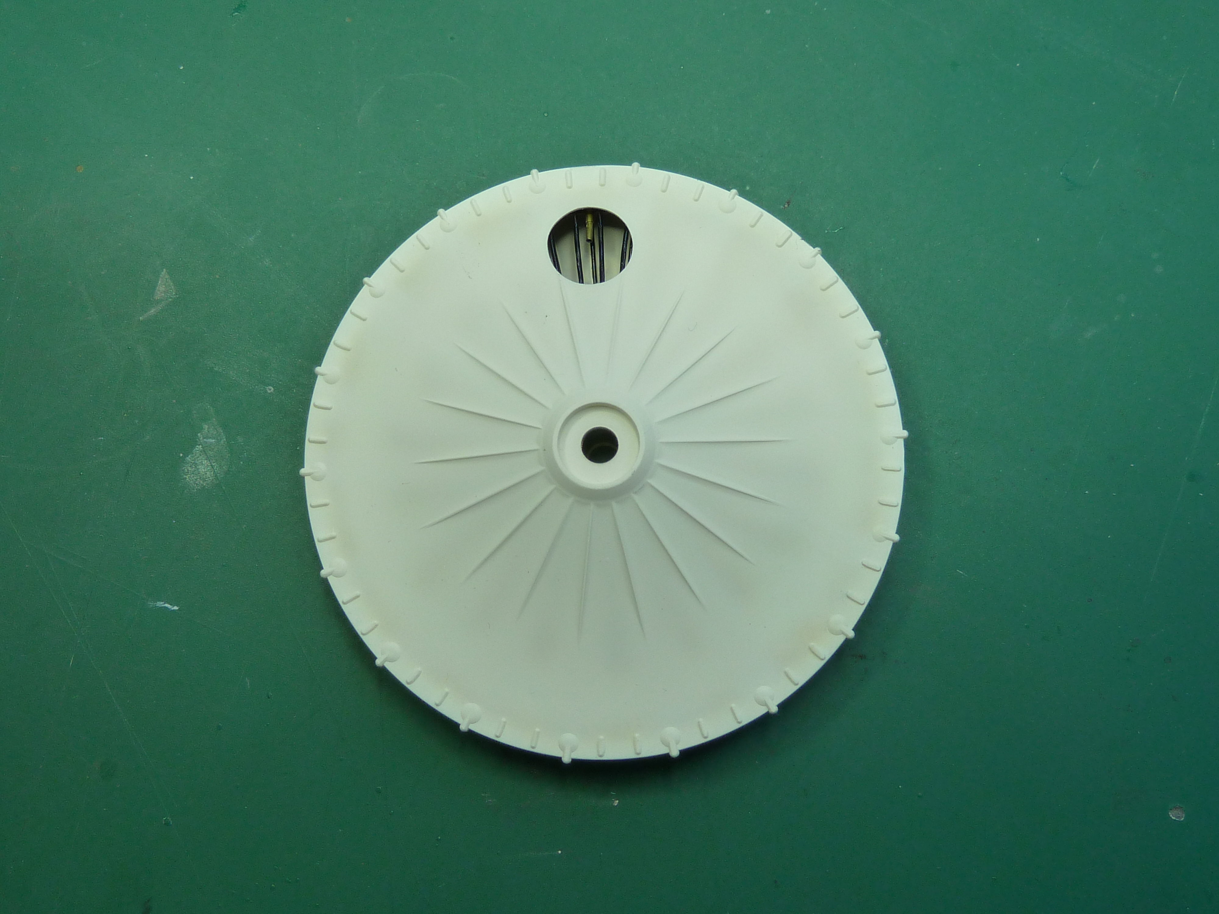
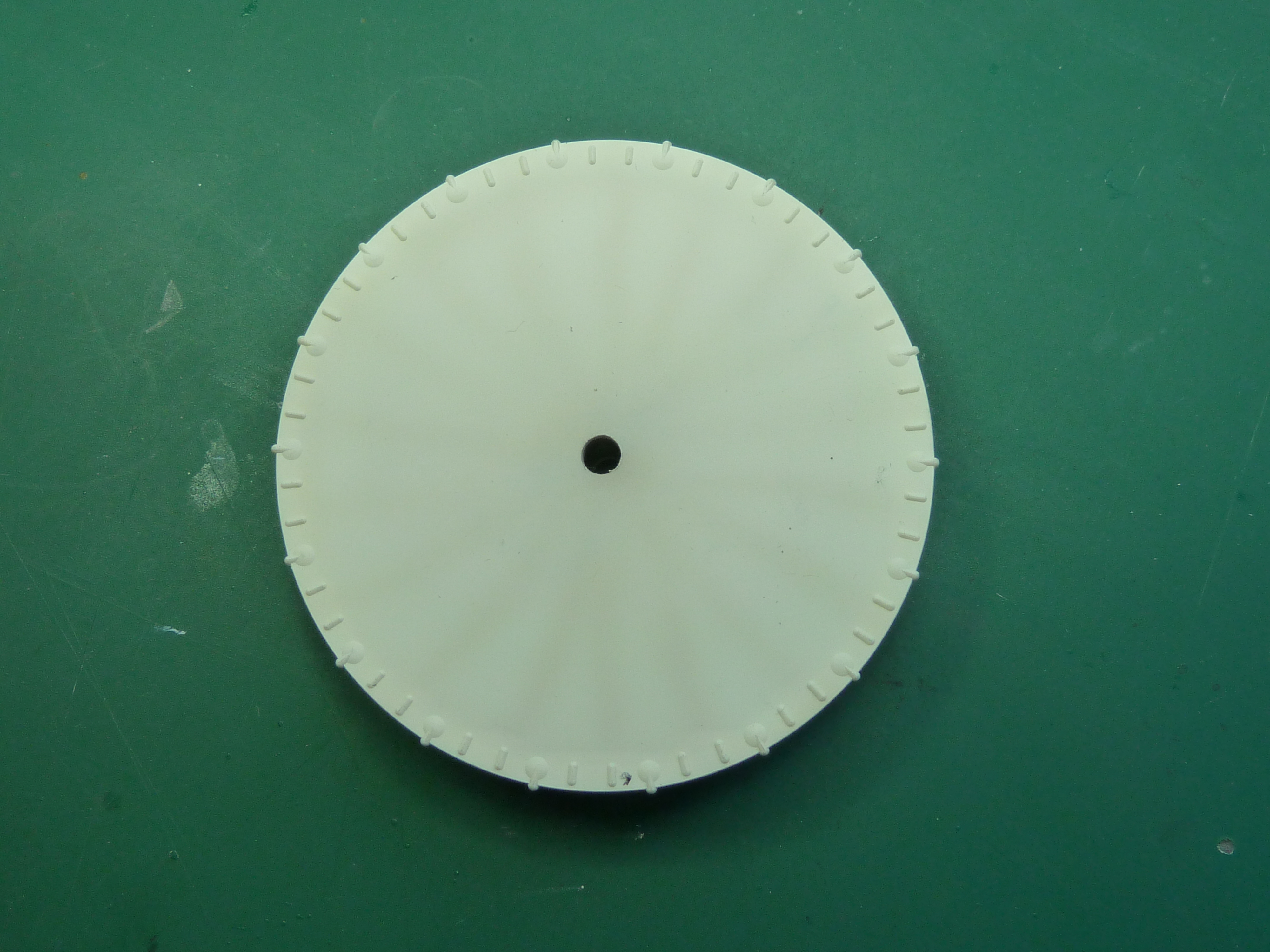
The saga of the wheels became a bit more involved than I expected. The ones in the kit are simple two piece affairs that depict the wheels in their covered form with some faux spokes and valve showing through a cut-out in the fabric

While they could probably be made into something quite acceptable, I wasn’t happy with the spokes’ moulding as they are bars rather than wires. I thought it would be relatively simple to carve them away and add some pieces of brass wire. Combined with some brass tube for the valve, it would look much more realistic.

The end result was pretty good to my mind, and a definite improvement for not much effort.

The success of this bit of detailing got me thinking. It’s my intention to finish the model half covered and painted and half as a skeleton structure. That way it will show the finished aircraft from one side and all the internals from the other. However, the wheels supplied by Hasegawa are both covered. If I was doing the aircraft half and half then one of the wheels really should be shown uncovered in its bare spoke format.
If the addition of a few wires had made the original wheels look better, how good would a fully spoked wheel look? I thought I’d give making one from scratch a go. The two biggest problems were where to get a nice circular rim from, and how to accurately drill the hubs and rims for the spokes. Getting the hubs accurate was going to be particularly awkward due to the size of them and the fact that I’m doing everything by hand. No indexing wheels available here.
First the rim: I decided to make this by constructing a hoop from laminated plasticard glued around a suitably sized former. I needed something 64mm diameter to match the existing wheel and tyre. luckily I found a glass bottle that was 62mm and was able to bulk it out to 64 with some aluminium tape

I made the rim by taking 3 strips of 30 thou plasticard, each of which would fully encircle the bottle on their own and laminating them on top of each other with the joints staggered around the circumference. The job was surprisingly easy and successful. The edges of the rim were cut from the same plasticard using a pair of dividers to score two concentric circles and then snapping them out carefully.
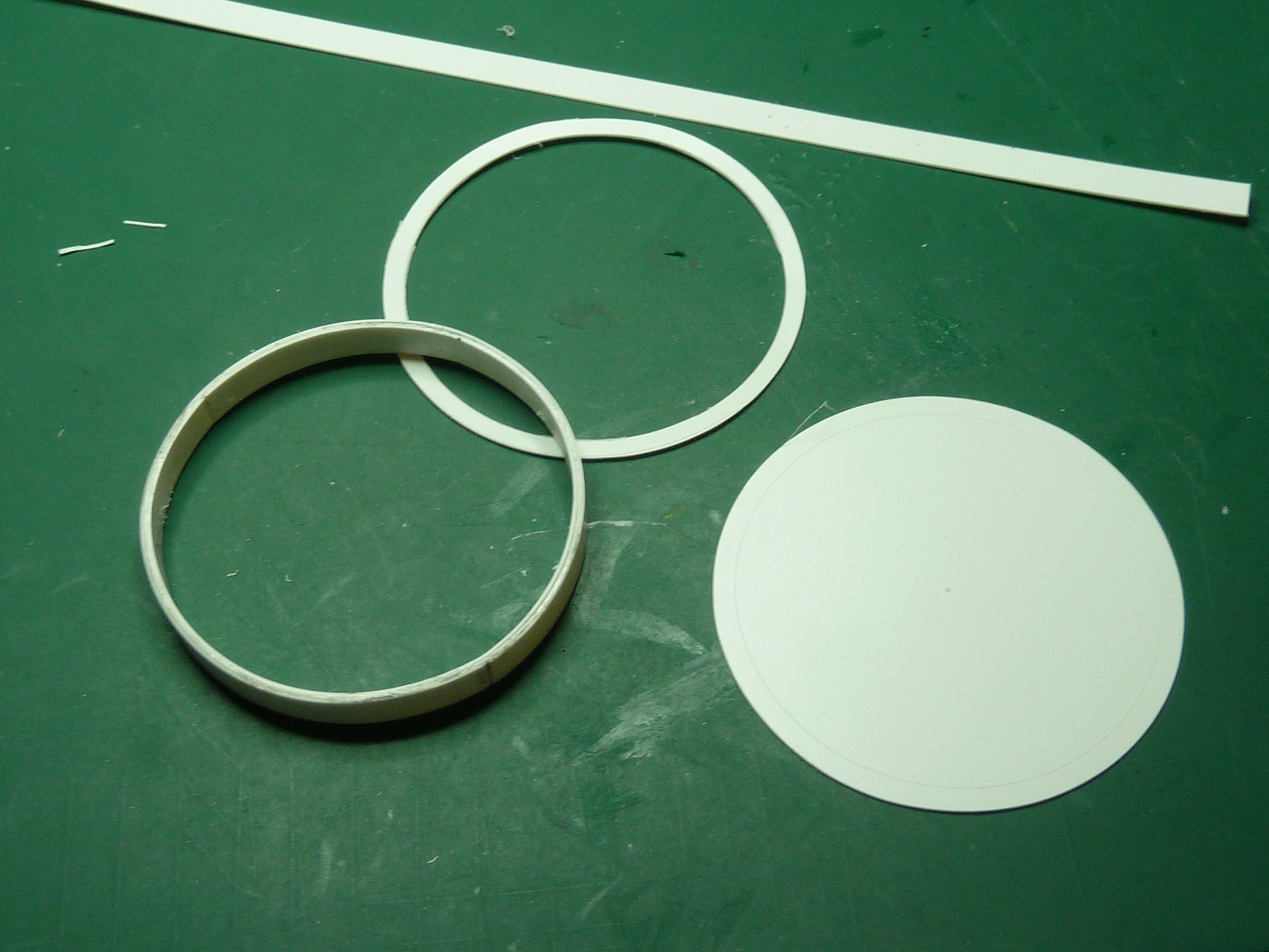
Attaching the edge pieces to the laminated rim was very easy as the bottle former for the rim also acted as a jig to ensure everything was assembled concentrically. So in a relatively short time I had…

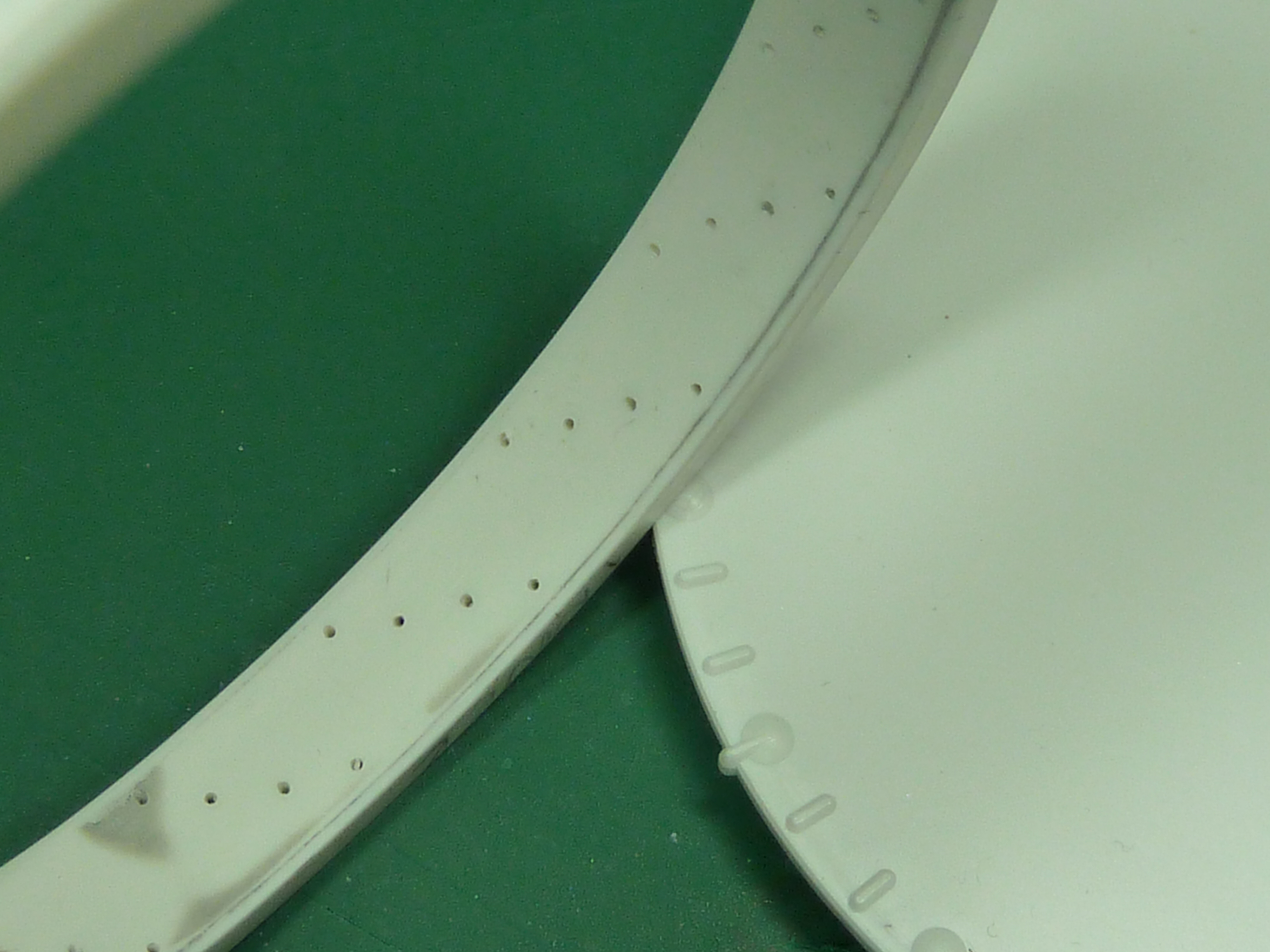
Next was drilling the rim to accept the spokes.
I used the wheel supplied with the kit to mark off where the spokes should go. As moulded they have 18 tabs around the circumference where the outer spokes meet the rim (have a look at the pictures above and you’ll see what I mean). This gave me an accurate starting index and all that was required was to divide the intervening gaps into 4 to obtain the positions of the intermediate spokes, giving 72 in total (36 on each side of the hub). Then it was a case of setting my dividers again to enable me to scribe the lines for the positions of the spokes across the rim which were arranged in 4 ranks.

Having got all the positions for the holes it was an easy job to drill them all out 0.5mm with reference to pictures of the real thing on the net.
Making the hub was more complex, mainly because of the size. The thing is only 11mm across and drilling 36 holes right next to the edge accurately distributed around the circumference stumped me for a while. In the end I decided to draw up a pattern in CAD and then print this out to scale as a decal. This would give me a ready-made and accurate drilling pattern. So a quick blast on the CAD and the decals were put on a couple of bits of 30 thou plasticard that had been laminated together to give me the required thickness of the hub rim.

Then it was a relatively simple job to drill and cut out the hubs using the decal template, fix a blanking piece of plasticard on the outer faces to hide the spoke holes and fix them to a length of 5mm plastic tube.
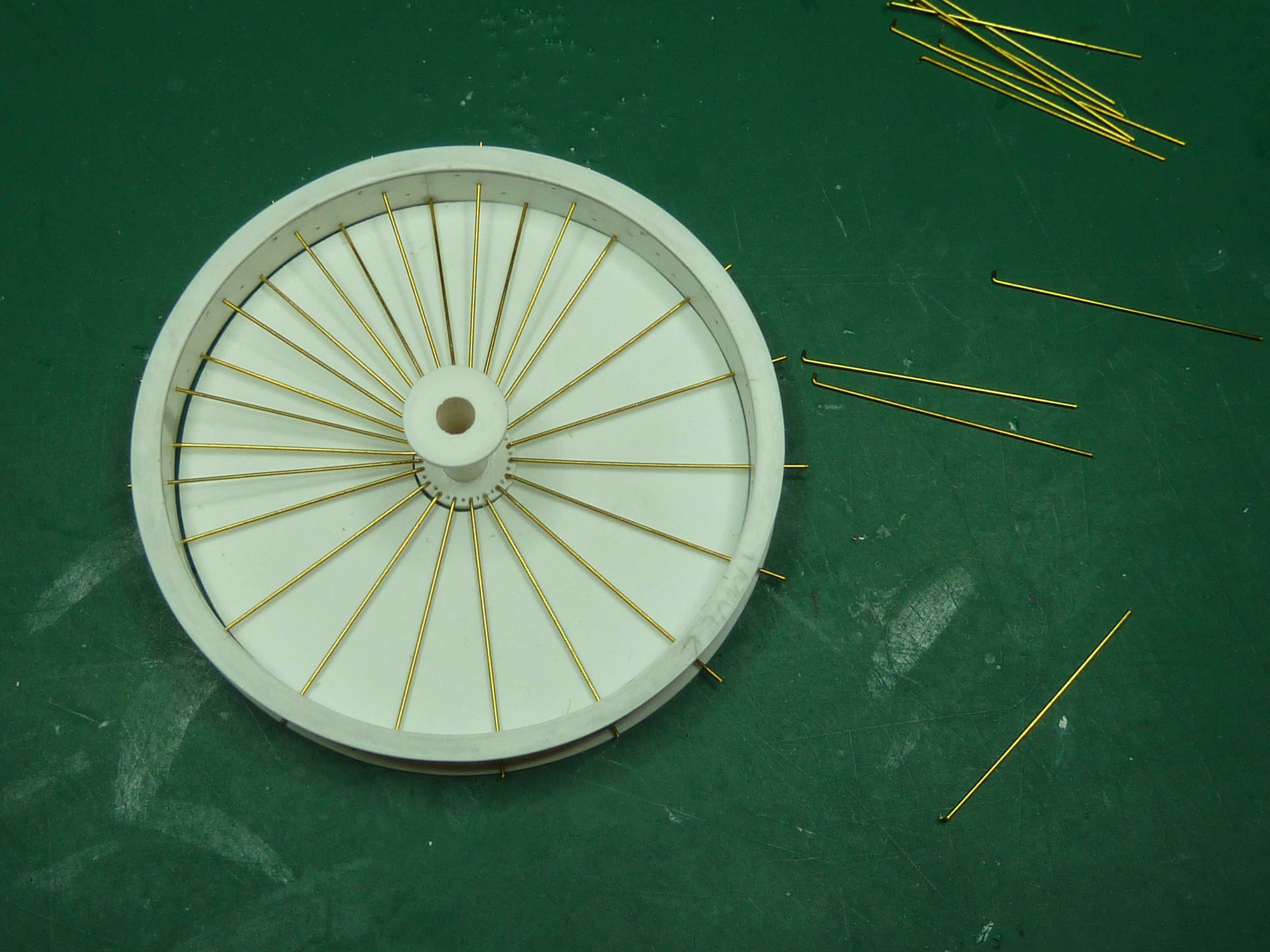
With the hub and rim complete the next step was the big one: it was time to actually assemble the wheel. I used one of the discs left over from the rim edge pieces as a jig to ensure everything was assembled concentrically. All that was required was to cut another 11mm diameter hole in the centre to hold the hub during assembly.

The spokes were made from 0.45mm diameter brass wire bent at one end to locate in the hub. luckily the Camel’s wheels are asymmetrical, one side is flat while the other offset outward. this made assembling the thing much easier as the flat side was all in one plane.
Actually fitting the spokes wasn’t the easiest thing in the world and intemperate language did occur at certain points. I wanted to get the whole flat side together ‘dry’ so that I could ensure everything was flat and centred before I doused the hub in cyanoacrylate adhesive. Several times one spoke came lose and trying to replace it made all the rest unravel. However as more spokes were fitted it became more stable and we got there in the end.
The second offset side was much easier as the whole thing was much more solid with the first side glued up.

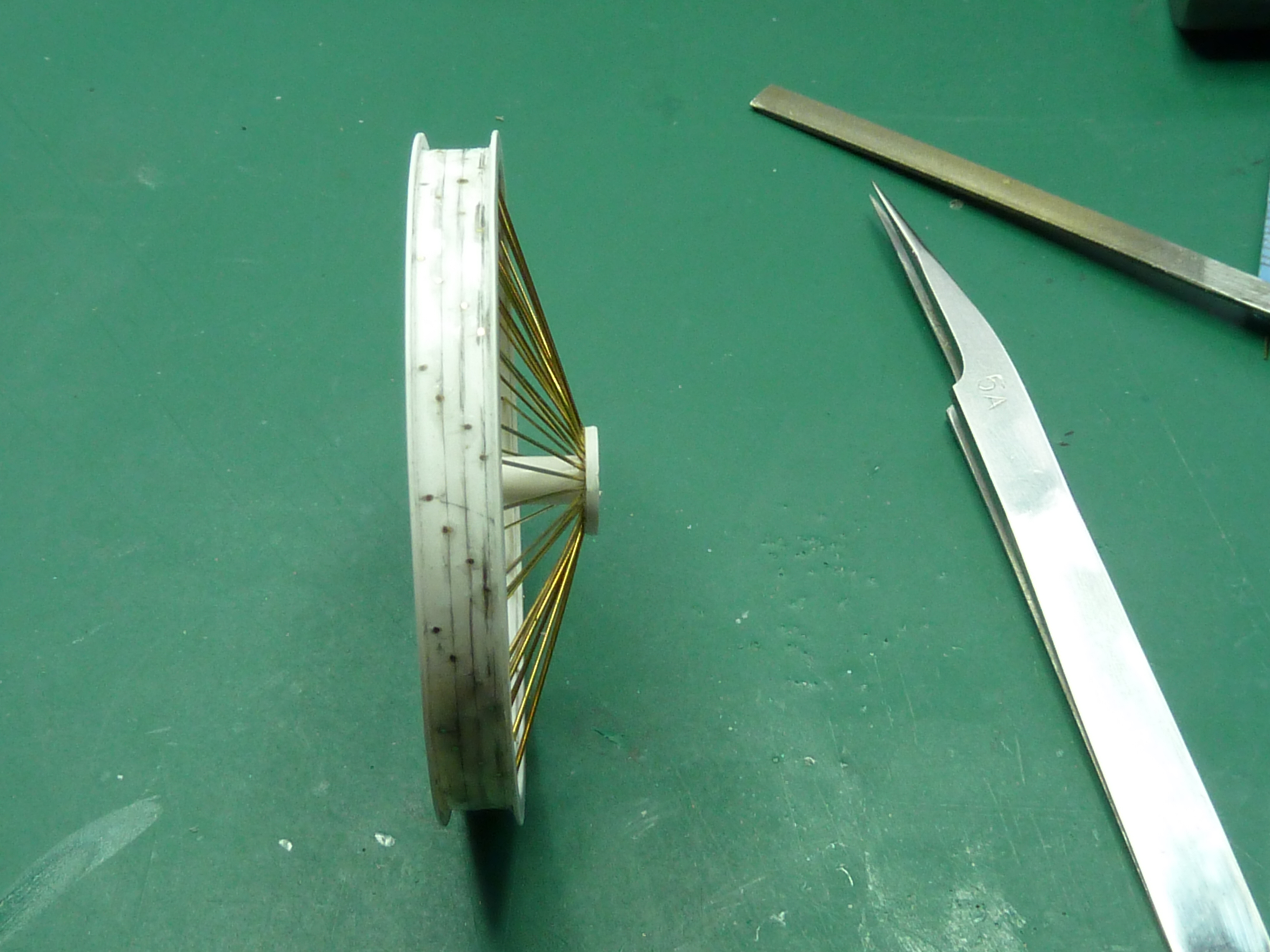
The only thing left was to add the valve assembly which was made from some brass tube bent to shape.

The valve was masked off and the whole wheel given a coat of Humbrol primer then a coat of gloss black.

in parallel with this I picked out the text on the kit tyres in white as per an old advertising shot of Palmer Aero Tyres that I got from the net. This was a painstaking task and took about 2 hours per side to get right. Not the most restful of tasks!

The final thing was to paint the other covered wheel that I started this post off with.
The aircraft that I am modelling had white wheels, so I pre-shaded parts of the covered wheel with a dark yellow to give some texture and interest and suggest the presence of spokes within the wheel. The wheel was then finished in a delicate off white colour, as I though pure white would be too stark.
After 4 days of effort the final result was pretty pleasing tbh. I’m very glad I put the effort into making the bare wheel.


Now onto the instrument panel….

Just incredibly beautiful work!!
I’m researching everything about this kit well before beginning construction (or even receiving/opening it) and sincerely appreciate and respect the effort that you expended in making this task MUCH more enjoyable and worth while for me.
Thank you very much!
JP
LikeLiked by 1 person
Thank you.
I’m actually building a second one of these as a commission. Coincidentally I’m assembling the wheels at this very moment. I’m doing this second set using brass hubs like my Fokker DR.1 as it’s easier to work more accurately in brass I find.
LikeLike