
Now it was onto a part of the build that I had been dreading. Covering the fuselage and rudder. As you will recall from earlier posts, my previous attempts to use Solartex on the kit’s plastic parts had been less than a runaway success, with the parts deforming irretrievably under the heat required.
I had been forced to remake the tailplane and aileron from scratch as a result. However, this would not be a practical prospect with the fuselage. That would effectively require the kit to be broken down and restarted. Not an attractive prospect at all. Indeed it might be the end of this build.
I started the fuselage covering with the rudder as if I could do that, the rest would be easy. What I needed to work out was a method of applying the heat to melt the glue on the Solartex and shrink it without allowing too much to build up in the plastic frame and so melting that.
I can now advise you that supporting the frame with your fingertips provides an excellent means of monitoring the heat build up with superb instant feedback when things were getting too hot. I highly commend it, but take care. The heating iron is at 130°C and about 2mm from your fingers, but I assure you that you are unlikely to impart too much heat to the part.
Here is the finished result after a quick paint job to buoy my spirits.


Having proved the new process I moved onto the main fuselage with considerably more confidence, not least because the fuselage frame is a much larger gauge of plastic and so less susceptible to heat build up anyway.
The first thing to do was to work out where the exits for the control lines would need to be cut once the fuselage was covered. I did this by means of creating a paper template referenced on the stern-post. The required holes were worked out by trial and error until a satisfactory template had been developed. A similar process was used on the tailplane (not shown here). The lines were run on the bare frame side and templates developed. These were then turned over and used to cut the required holes on the covered side.
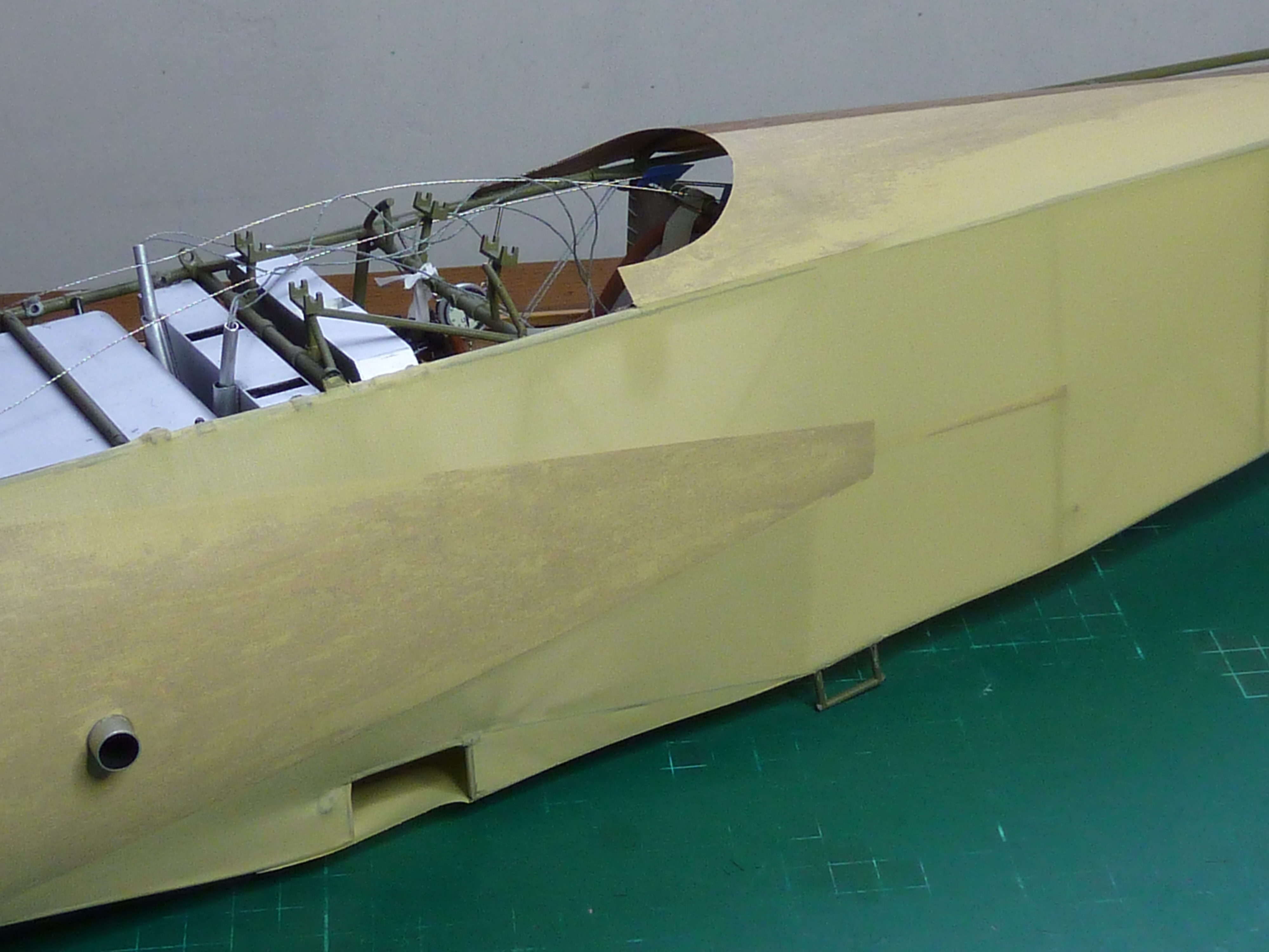
Here’s a shot of the work in progress. Rudder cable done, elevators still to go.

Once the control line template was completed the covering began. The real aircraft was done in one piece I believe. The covering was like a sock that slid over from the rear and then laced up along the underside centreline. As I was only covering half the fuselage that would not be possible for me. In the end I covered it with two pieces, the join being along the lower longeron. The join can be seen, but only if you look closely, otherwise it’s invisible.
The start of operations: Cutting out the basic shape.

The finished article ready for masking and paint.
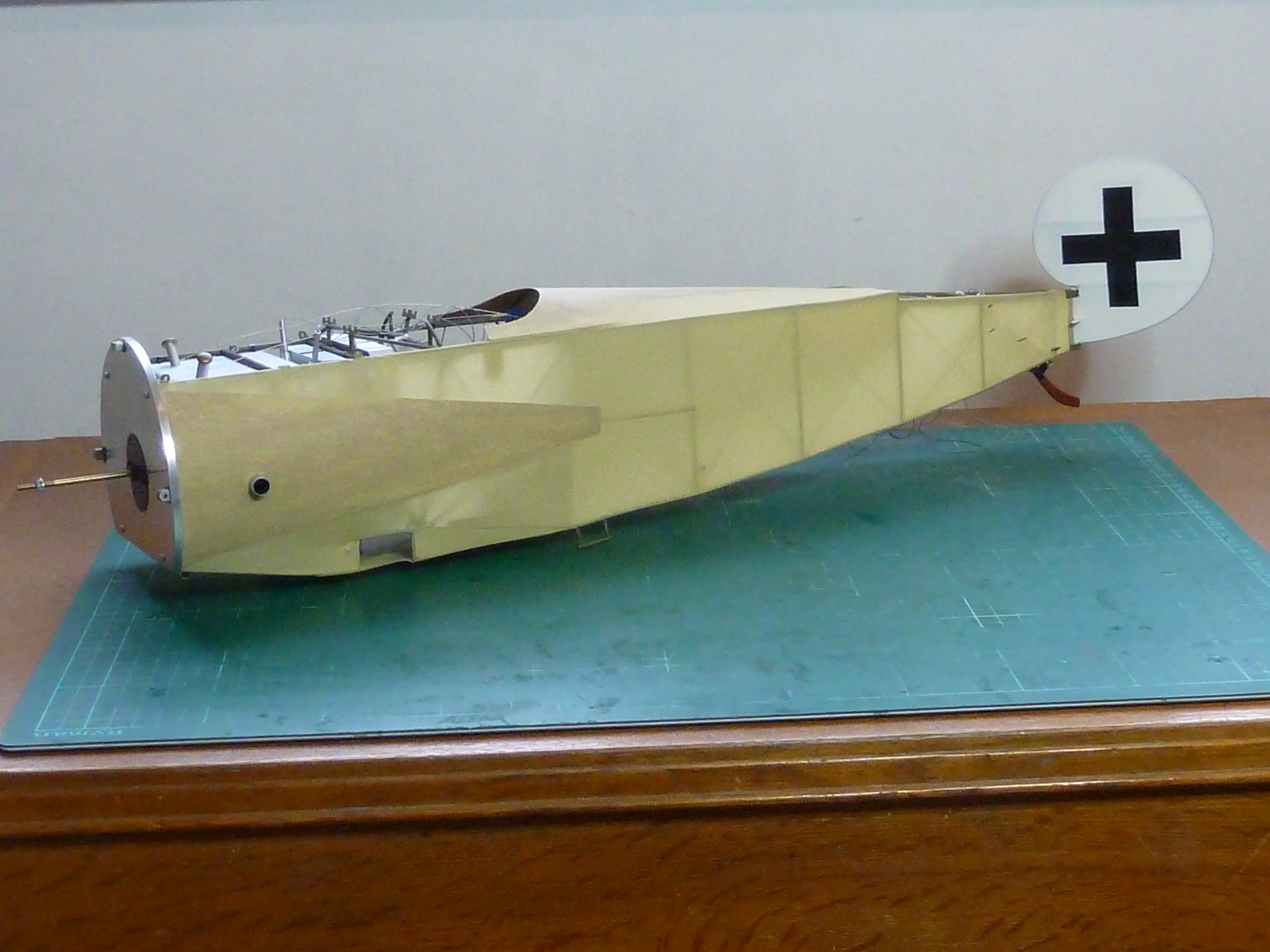
Masking and painting was a simple affair. A quick coat of Halford’s red primer, then several coats of Nissan Flame Red AJ4. As before on the Camel, the Solartex I used was the ‘Antique’ as this is slightly translucent which means that the correct colour is obtained on the rear side of the covering when viewed from the cockpit or rear fuselage.

Note the cockpit coaming padding is temporary while I decide how to develop a more realistic offering.
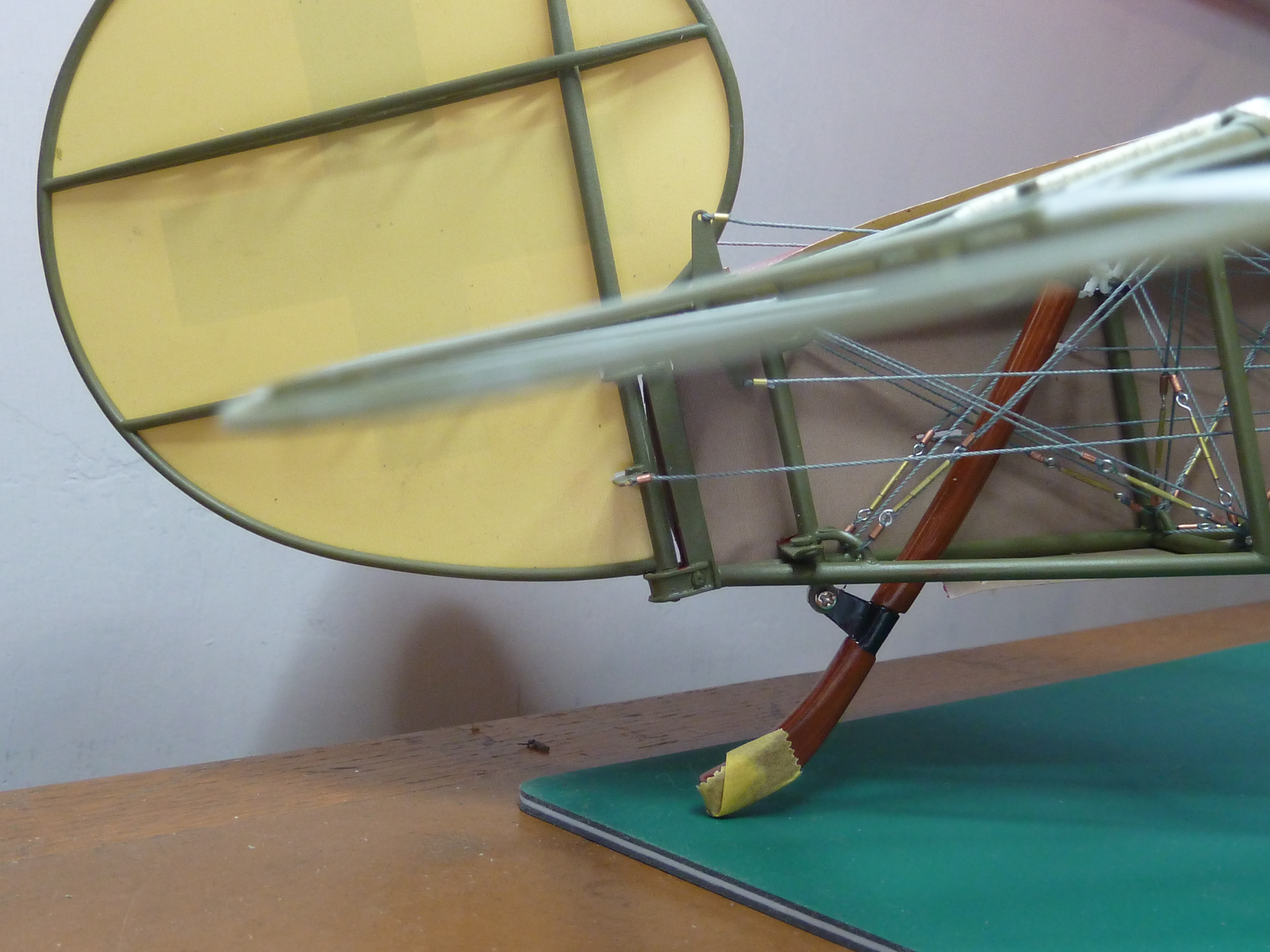
You can just see the simulated holes for the underside lacing in the picture below. You can also see that I have achieved a proper straight edge on the covering this time, unlike the wavy one on the tailplane. I managed it by covering all of the underside, painting it fully and then finally cutting it to size. This means no masking is required at the edge for painting, the removal of which caused most of the distortion. A similar technique was used on the undercarriage winglet, which you can see in the full aircraft pictures.

The picture below shows the difference of the white and red areas when viewed from the inside surface.
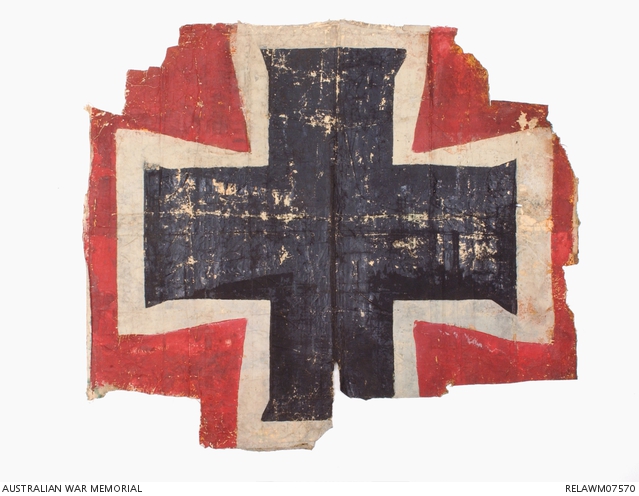
With the fuselage covered and painted the next step was to add the Balkenkreuz. I’m not trying to replicate the exact finish of the real aircraft on this model. I’m aiming at a stylised ‘engineering example’ finish, so I’ve made no effort to weather the aircraft, replicate scratch marks or emulate the repeated overpainting of the insignia. The latter went through several variations from the original ‘Iron Cross’ to an interim Balkenkreuz, then a final standard as the various orders were promulgated from above. The net result was that the actual crosses on Richthofen’s aircraft were a bit of a mess when viewed closely and nowhere near as pristine as the ones I have painted on this model.
Here’s one taken from Richthofen’s crashed aircraft. It is in the final standard with a 3:1 ratio of cross thickness to width. I have chosen to paint my model with the interim standard which has a 4:1 ratio.
The basic masks were cut from medium tack ‘Frisket’ and airbrushed on using Tamiya acrylics. When completed, they were given a coat of satin varnish to protect them and also blend them in with the glossy fuselage.

Then it was the job of starting to install the wings.
As with so many jobs on this model, this was made much more difficult by the fuselage mods around the cockpit area that I had made earlier. I had checked all the clearances while I was incorporating the changes, but had cut them fine which meant I didn’t have much leeway when attempting to install the wings.
Everything went together in the end, but was much harder than a build to print effort I suspect.

Now was also the time when I finally fitted the machine guns and the aluminium panelling around the cabane strut mountings. Again, because of the way I’d chosen to assemble the aircraft, this was much more difficult than a standard build would be. To avoid visible joints in the cabane struts I’d assembled and painted them off aircraft rather than in situ. It makes fitting the panelling more difficult, but it is still possible, and the end result is better I think.
I also filled the original hole in the panelling for the empty cartridge belt return from the port machine gun and drilled a new one slightly further forwrd to allow the revised feed to go to the new forward ammunition bin.
The revised panel and feed chute is shown below.

The feed chute still looks a little thin to me, but it would have required substantial mods to the machine guns to change things and wasn’t something I wanted to get into. The revised feed chutes are PVC covered single core wire of about 3mm diameter.
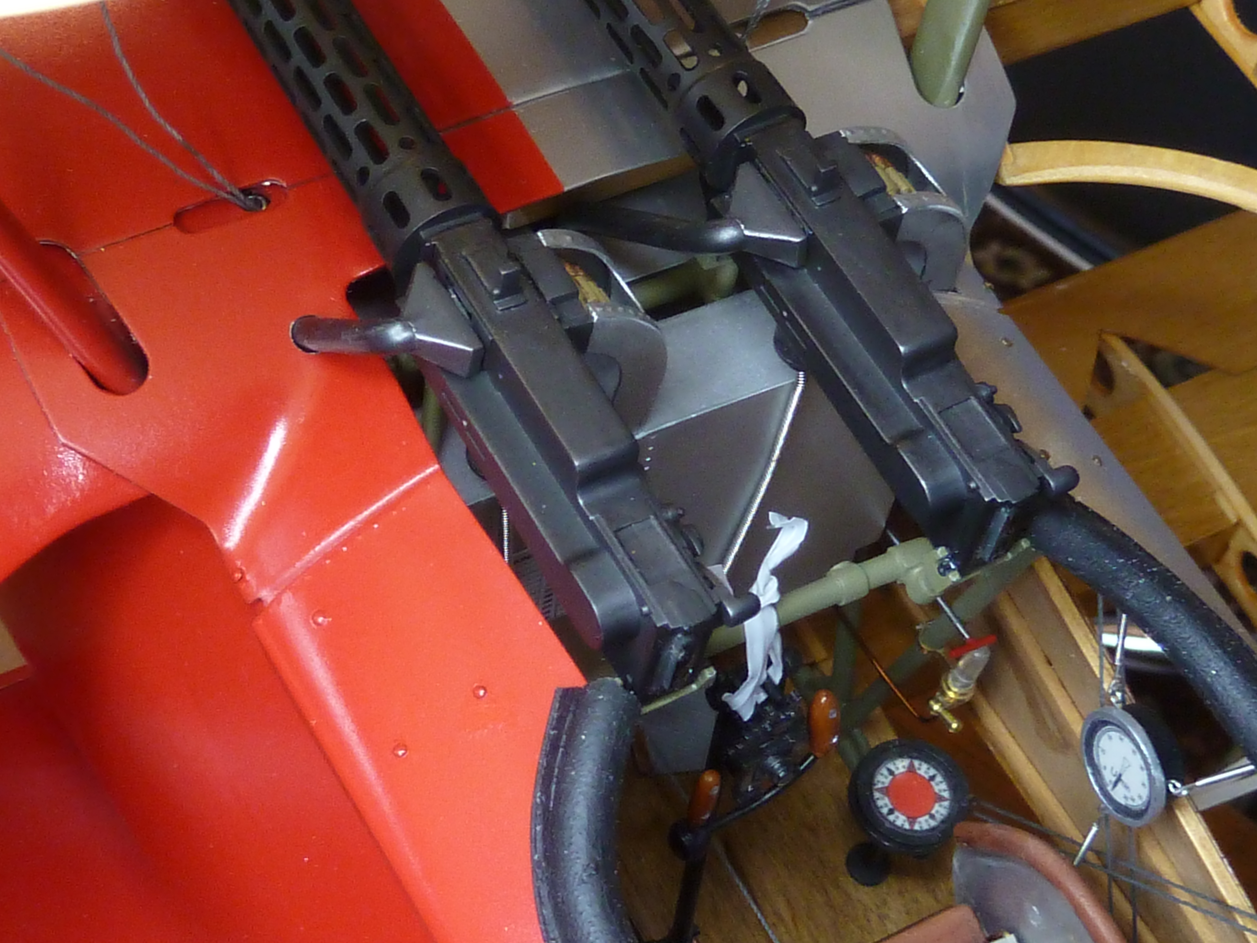
In addition to the revised return feed chutes, I’ve also added the empty cartridge guides below the guns. For some reason these seem to be missing off a lot of DR.1 models. I’ve made them from brass sheet bent around a hardwood former. You can see a mock-up of them below.

The spent cartridges were ejected forwards from a small hole underneath the gun and then simply rolled down the chute and out onto the fuselage surface and then fell overboard. It wasn’t a very satisfactory installation to my mind as it was apparently not unheard of for the hot spent cartridges to be caught in the slipstream and blown back into the cockpit and pilot’s face, not that he would have been busy with any other activities when he was firing his guns of course. Herman Goering’s DR.1 had special adapted chutes which were significantly enlarged to overcome this problem, but they were unique to his DR.1.
Here are the panels installed, but prior to the machine guns being put in.
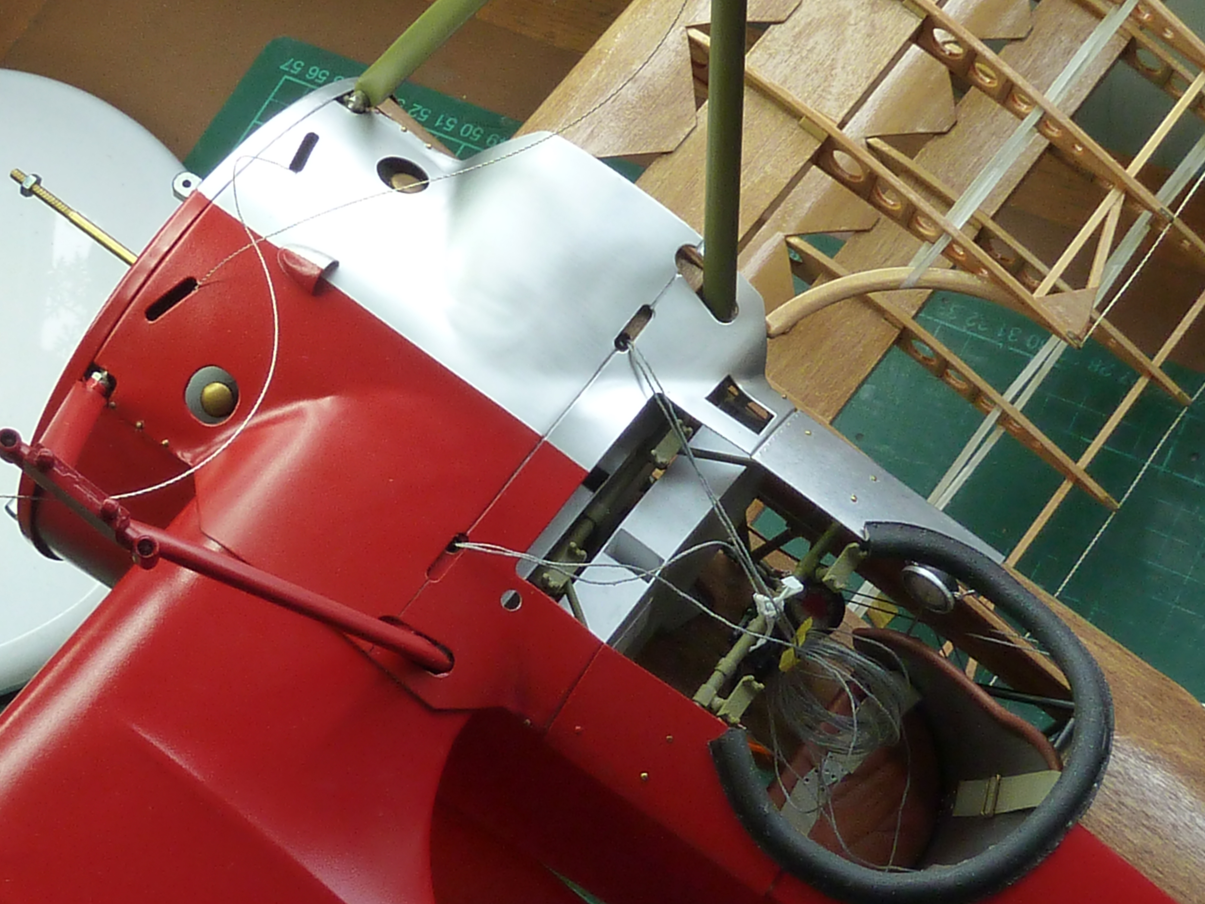
As mentioned briefly before, I’d replaced my original interrupter gear connections to the guns with guitar strings which looked much more realistic. You can just see the one from the starboard gun in the picture below.
The wire tie on the control column is there to stop it flopping about and chipping the paint on everything, as until the control lines are connected and taut there is nothing to stop it moving about.
The photo below is taken looking forward from the underside and shows the connections of the other ends at the engine bulkhead. This whole area is pretty well covered up by the lower aluminium panel described earlier in this blog.

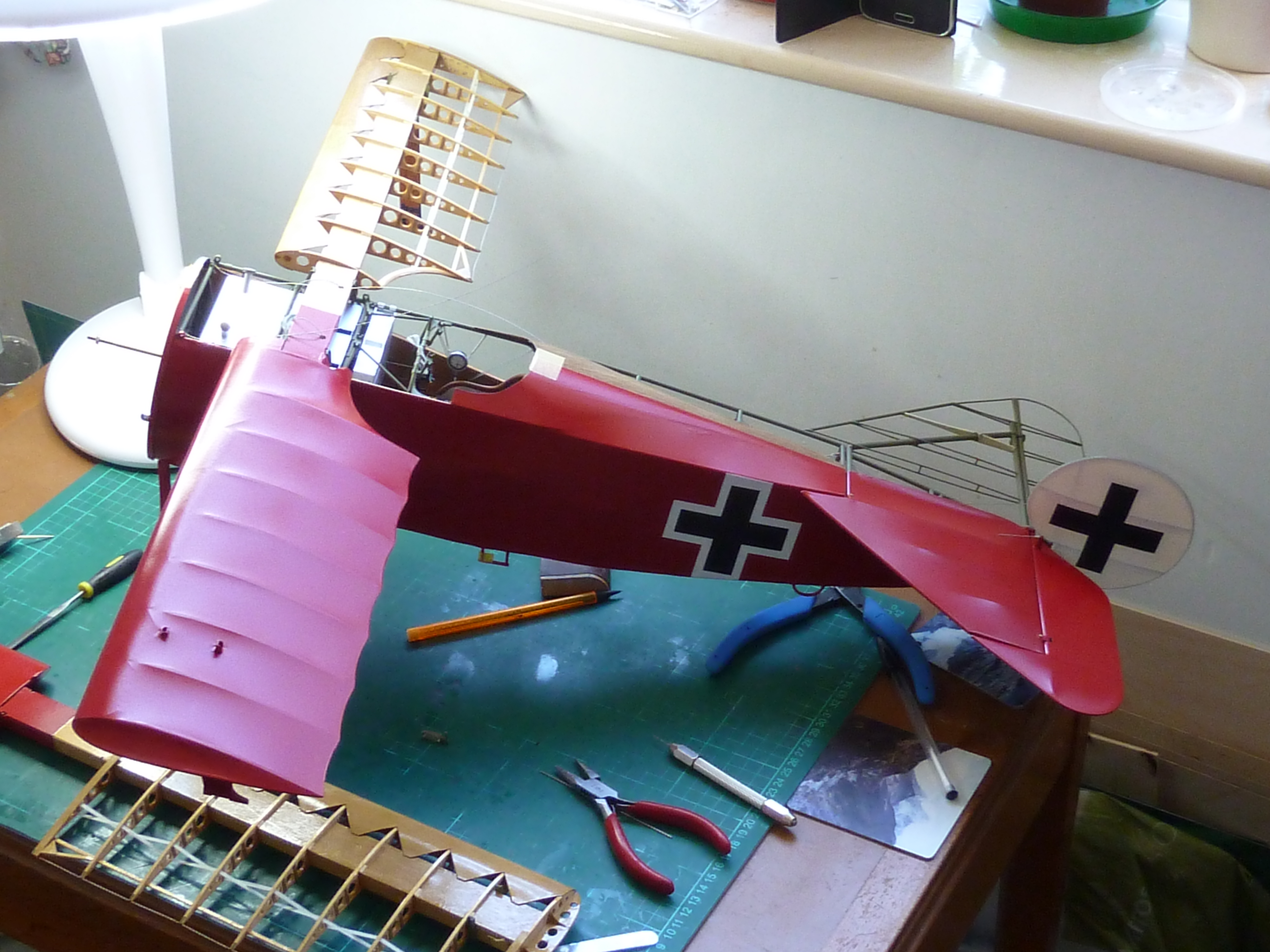
I’ve now reached the stage where the lower and mid wing are in place and the cabane struts for the upper wing. I haven’t finalised exactly how I am going to manage to install the control line runs and cover the wing yet. The model lacks the very useful access windows that the Camel had so I may be forced to use patches on the outer fabric. It’s that or install the wing, run the control lines, cover and paint in situ, which I’d like to avoid if I can.
Here’s the current state of things with the upper wing installed for the control line cut-outs through the covering to be worked out and paper templates developed.

