
One of the areas where this kit departs quite markedly from the real aircraft concerns the decking on the fuselage, particularly aft of the cockpit.
In fact the aft decking is omitted completely and some spurious curved fuselage cross members added in its place. The decking that is supplied around the cockpit opening also continues further forward than it should, replacing what were a couple of aluminium panels in reality.
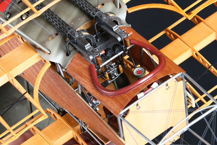
Here is a picture of the model built as it was designed.
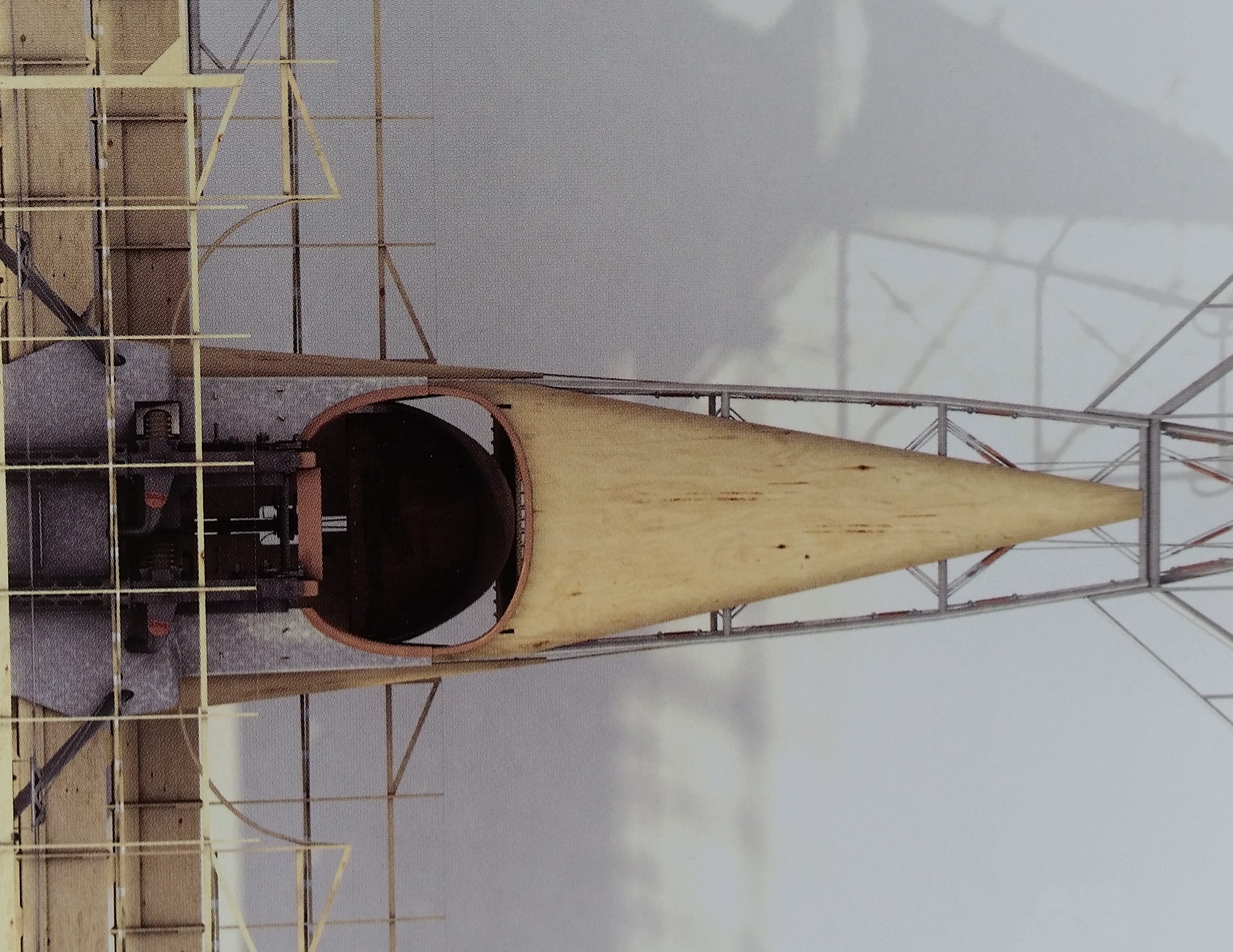
and here is an excerpt from the Kagaro book, referenced in part 1 of this build log, which clearly shows the missing decking and aluminium sheeting around the cockpit.
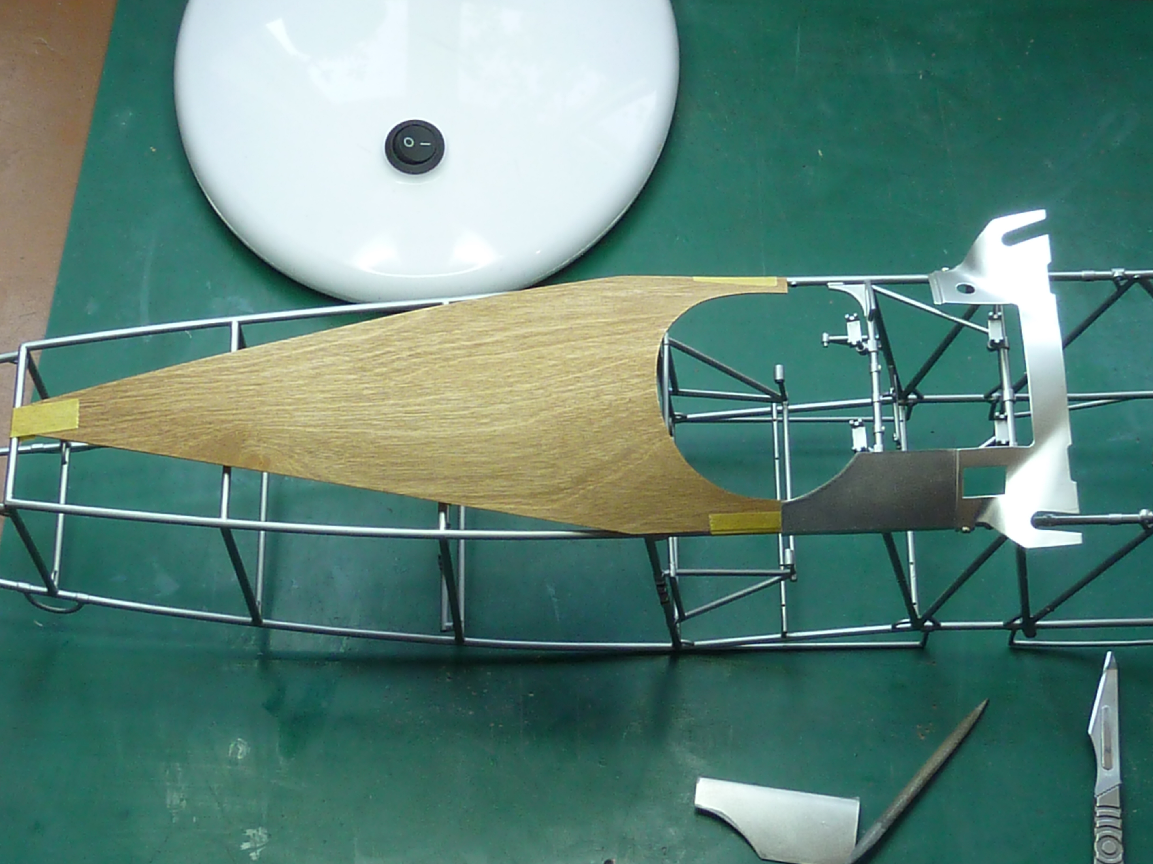
The rear decking was relatively trivial to add, however it did require a couple of frame hoops to be removed from the top face of the frame. The one in the kit immediately behind the cockpit is OK, but I can find no reference to the two further back in drawings or contemporary photos of the aircraft.
I made the decking from 0.6mm birch plywood stained with Liberon’s ‘Antique Pine’ wood dye again. I also added some stringers to the underside of the panel as these are shown in some references.

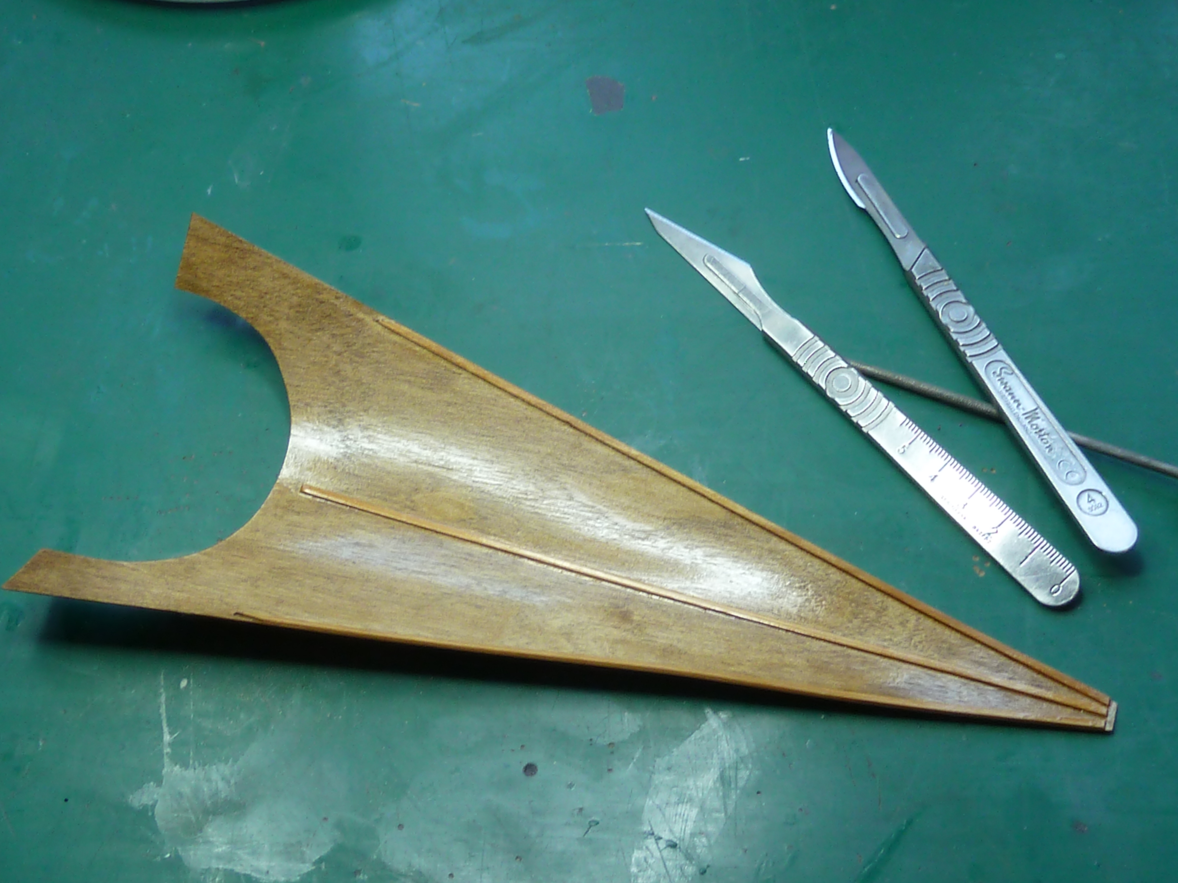
Getting the profiling right around the cockpit area was a little awkward and as a result I ended up scrapping my first attempt and remaking it.
The small aluminium parts were also fairly straightforward. I made them out 0.3 mm thick sheet using the supplied veneer part in the kit as a template. A lot of offering up and fettling went on before I achieved a shape that looked right and was symetrical across the fuselage.

The panels were then detailed with some fake rivets made by pressing a small drill into the rear face of the aluminium. Some mounting holes were also drilled to add some fasteners at a later date. 2 of these will actually help secure the panel to the frame, while the third is fake.

The fake fastener has actually already been glued in place in the pictures above.
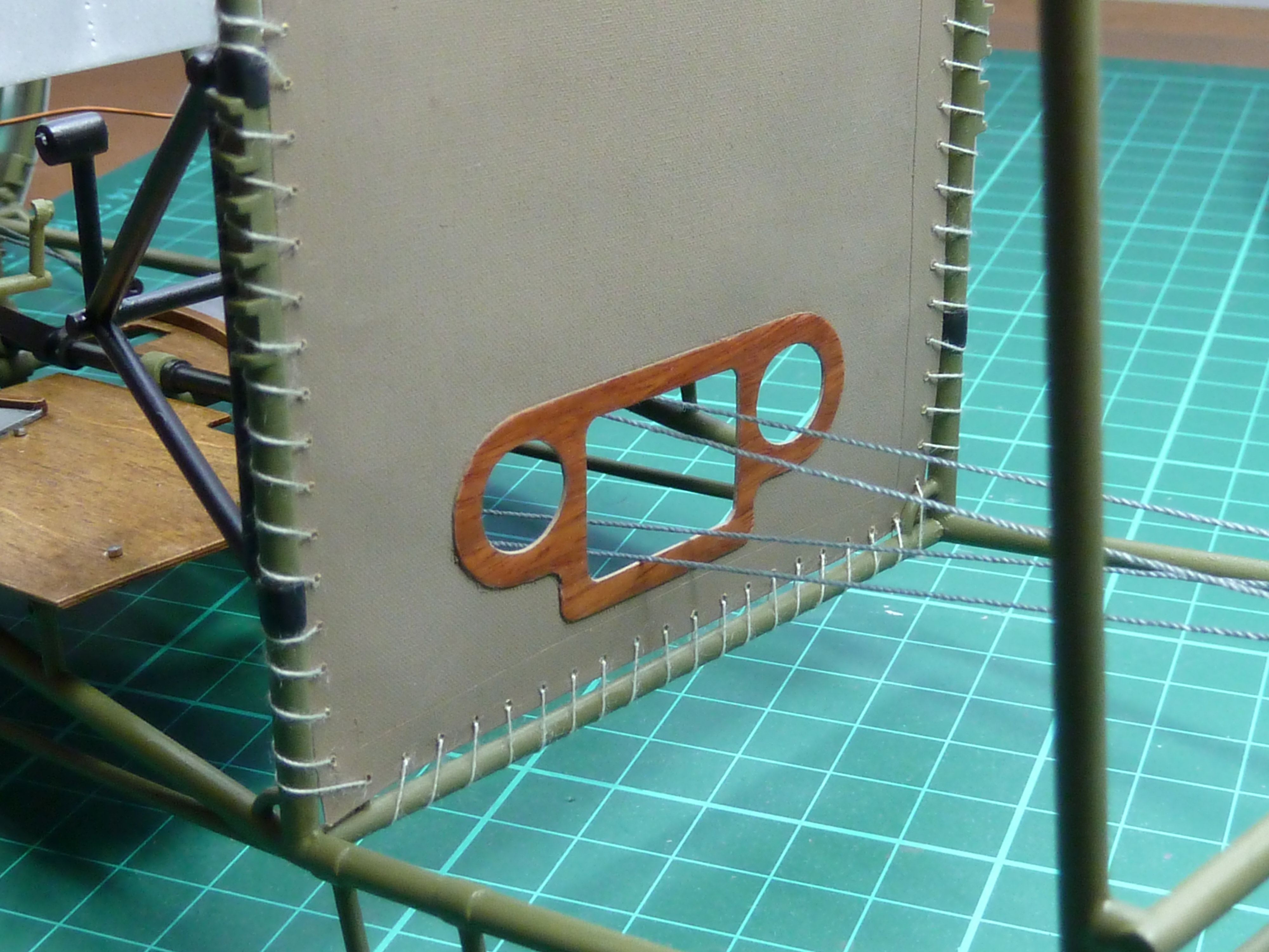
Whilst I was messing about in the cockpit area I decided to add the canvas screen that forms the rear ‘bulkhead’. This was incorporated to stop the ram air pressurizing the rear fuselage and making the linen covering balloon outwards. On the Camel, Sopwith simply left a large open section around the tailskid to let the air out.
The kit part is another piece of 2 mm plywood secured by 4 off M2 bolts. It might make for a strong model but it’s nothing like the real thing and completely out of scale for the model, so it had to go. I’d already removed the mounting lugs on the fuselage frame when that was assembled, so all that was required was for a suitable replacement to be made and installed.
I made the replacement out of Solartex (2 pieces back to back, one slightly larger than the other so the edges could be folded over) and used a little of the spare rose coloured veneer supplied in the kit for the fuselage decking to simulate the wooden stiffener around the control line access holes. The whole thing was then painted in what I thought was a realistic colour. The finished part and the kit part are shown together below.

The canvas screen was held in place in the real aircraft with thin cord laced around the fuselage tubes, so I emulated that using cotton thread.
The end result is pretty pleasing and adds a nice feature to the aircraft. It’s certainly a lot better than what Hasegawa provide.
Next up a bit of a medley of cockpit detailing…

Excellent work!
I have this in the ‘stash’ too – time to start building… :O)
LikeLiked by 1 person
Good luck. I’d be interested to hear about your progress.
LikeLike
Really beautiful job. First the Camel, now this. Wonderful and inspirational
LikeLiked by 1 person
Thank you very much.
LikeLike
Your metalwork is excellent: most modelers miss the panels around the cockpit. I’m very impressed by your fuselage baffle and stitching. Well done!
LikeLiked by 1 person
One thing that I discovered after finishing the model is that the baffle should actually extend up to the curved support for the decking, which is obvious in retrospect as it is there to stop ram air filling the rear fuselage and the ram air effect will be at its worst at the very top.
Sopwith got around the problem by leaving a big hole around the rear skid for the air to escape.
LikeLike
You are correct that there was a second (upper) baffle section of fabric laced to the horizontal crossbar and the curved crossbar just above. Having said that, yours is spectacular. I have over 1500 photos obtained from Achim Engels during one of his Dr.1 replica builds and this kind of detail is covered to extremes.
LikeLiked by 1 person
You’re relying on Kagero? That is a bit problematic for me. I wrote a book on the Il-2 Shturmovik and found multiple errors in the Kagero Il-2 book and in their plans. And that is with an aeroplane which still has extant examples. I’d take Kagero with a grain of salt.
LikeLike