
Progress has continued on the Fokker, with the kit seeming to fight me at every stage. A lot of it has been down to me though. I seem to be making quite a few mistakes at the moment, particularly in the planning of the build sequences.
One of the trials of modifying a model and deviating from the planned build is working out when and how the changes should be implemented in the standard build. Something I’ve not been doing well on this model which has sapped my enthusiasm a bit as I’ve had to undo and redo work several times.
In order to get a quick feeling of achievement I put some of the sections giving me grief, like the tailplane, on ice and decided to have a go at the wings. What could possibly go wrong?
As I’m doing the port side of the aircraft covered I started with the lower port mainplane and built it strictly to the instructions. The idea being to get an understanding of how Hasegawa intended them to go together before I started tinkering with them.
The assembly is pretty straightforward and follows the usual pattern for this type and scale of aircraft. First lay down the spar and then add ribs and leading and trailing edges.
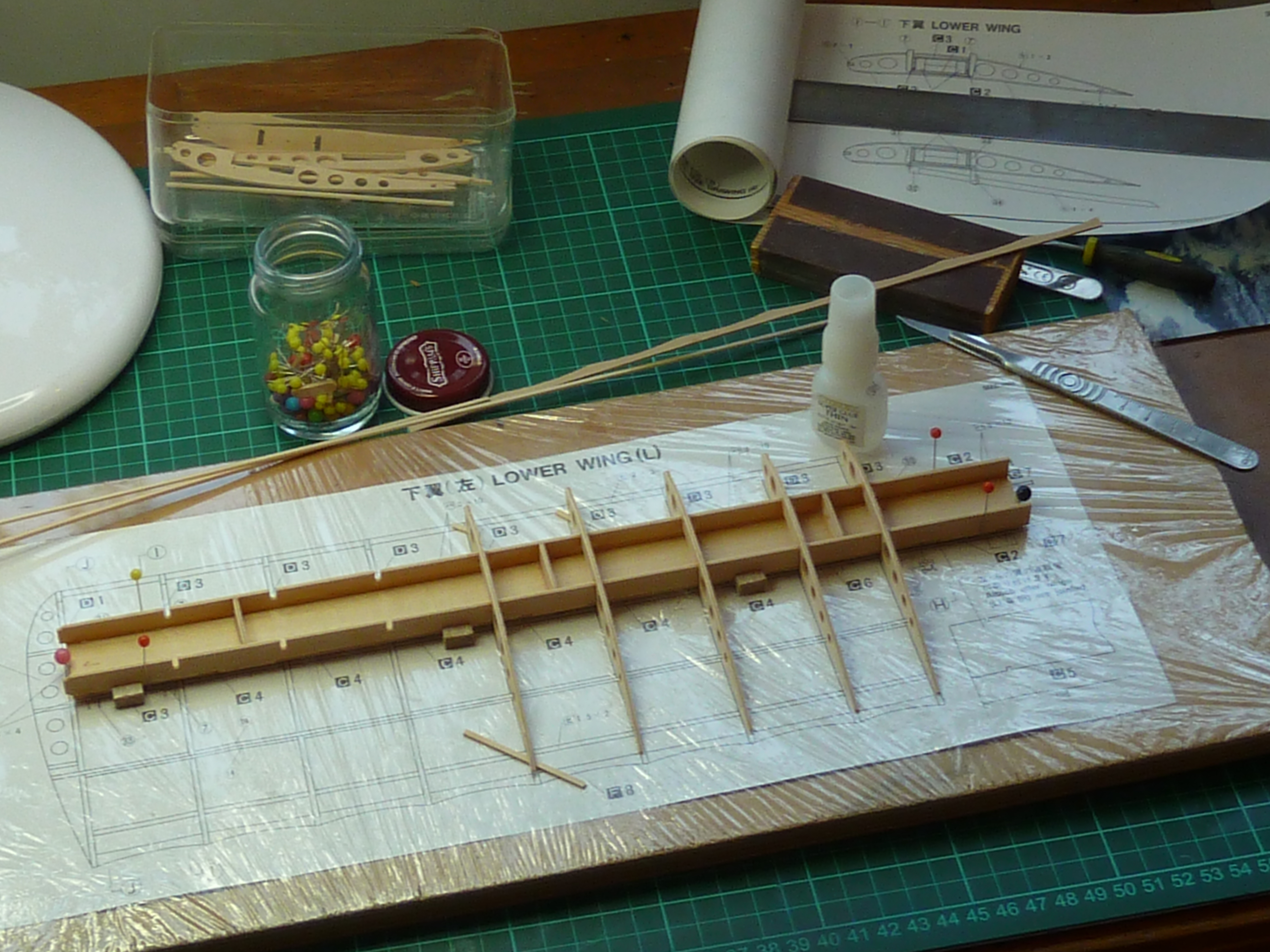
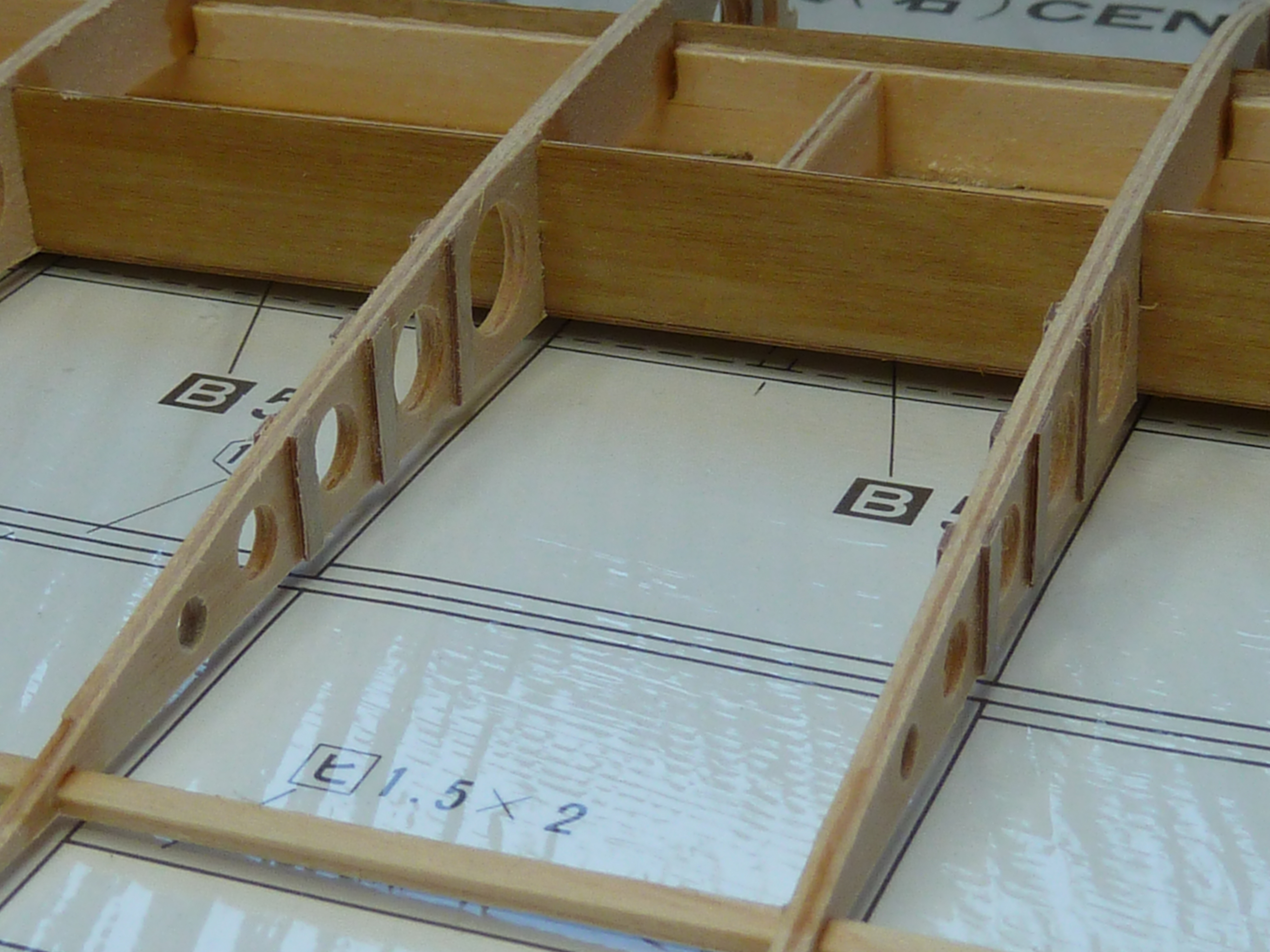
The Dr.1 was unusual for the time in having a box section main spar which was strong enough to act as a cantilever for the whole wing allowing the DR.1 to be built with minimal rigging . The kit follows this practice though the plywood used is very overscale, the grain goes in the wrong direction and it has some unsightly location tabs which are quite visible.
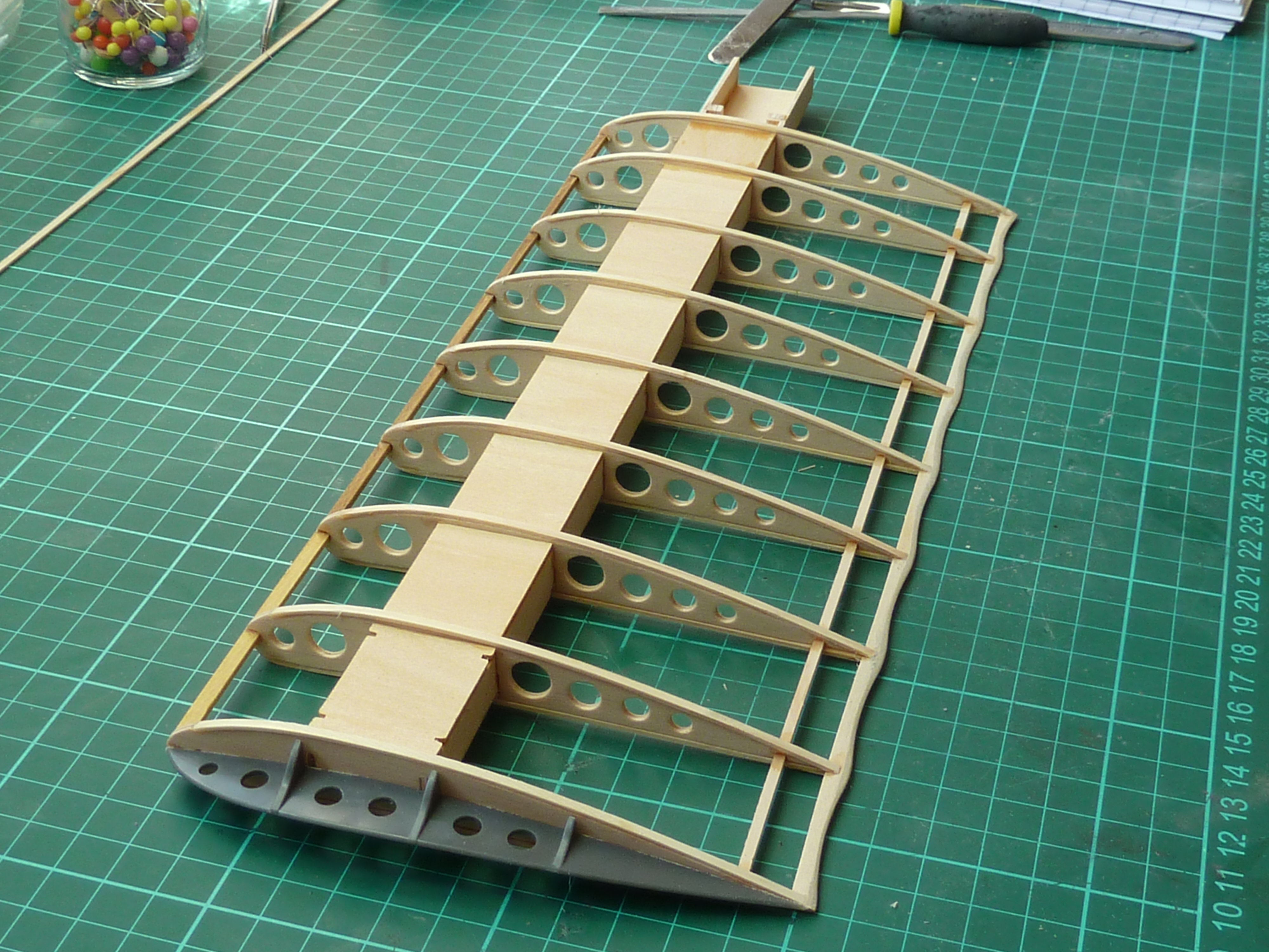
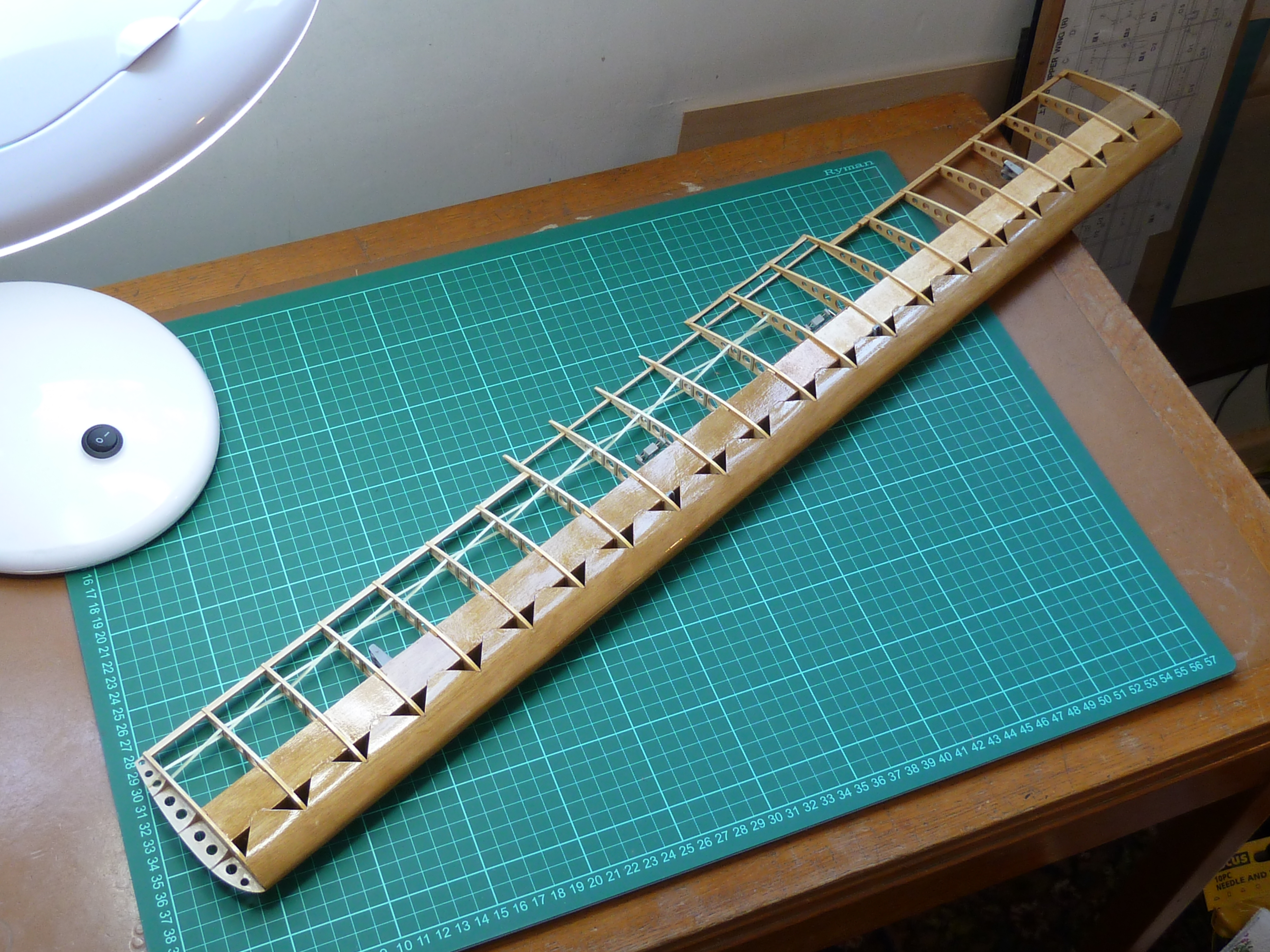
Here’s the finished wing.
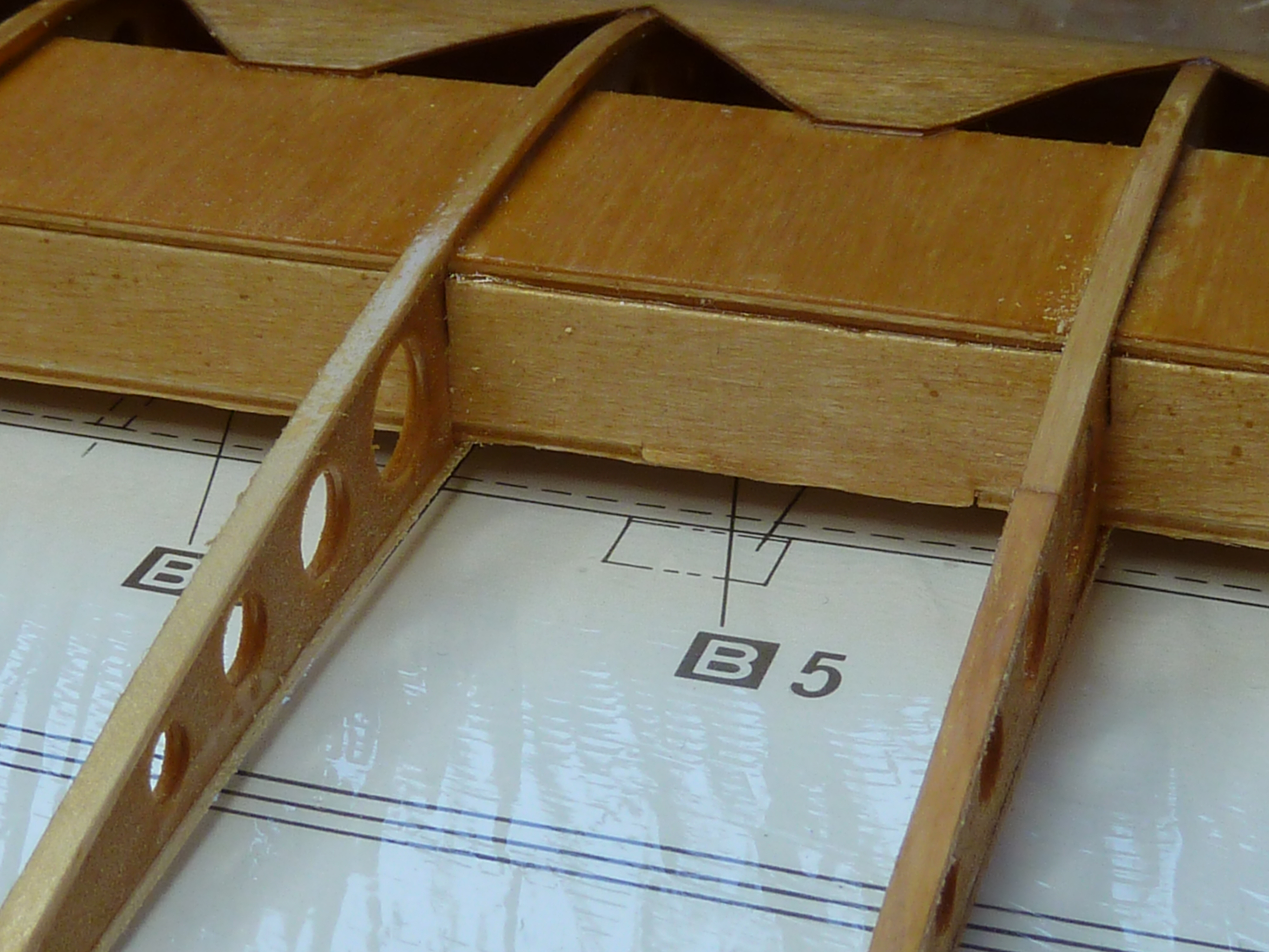
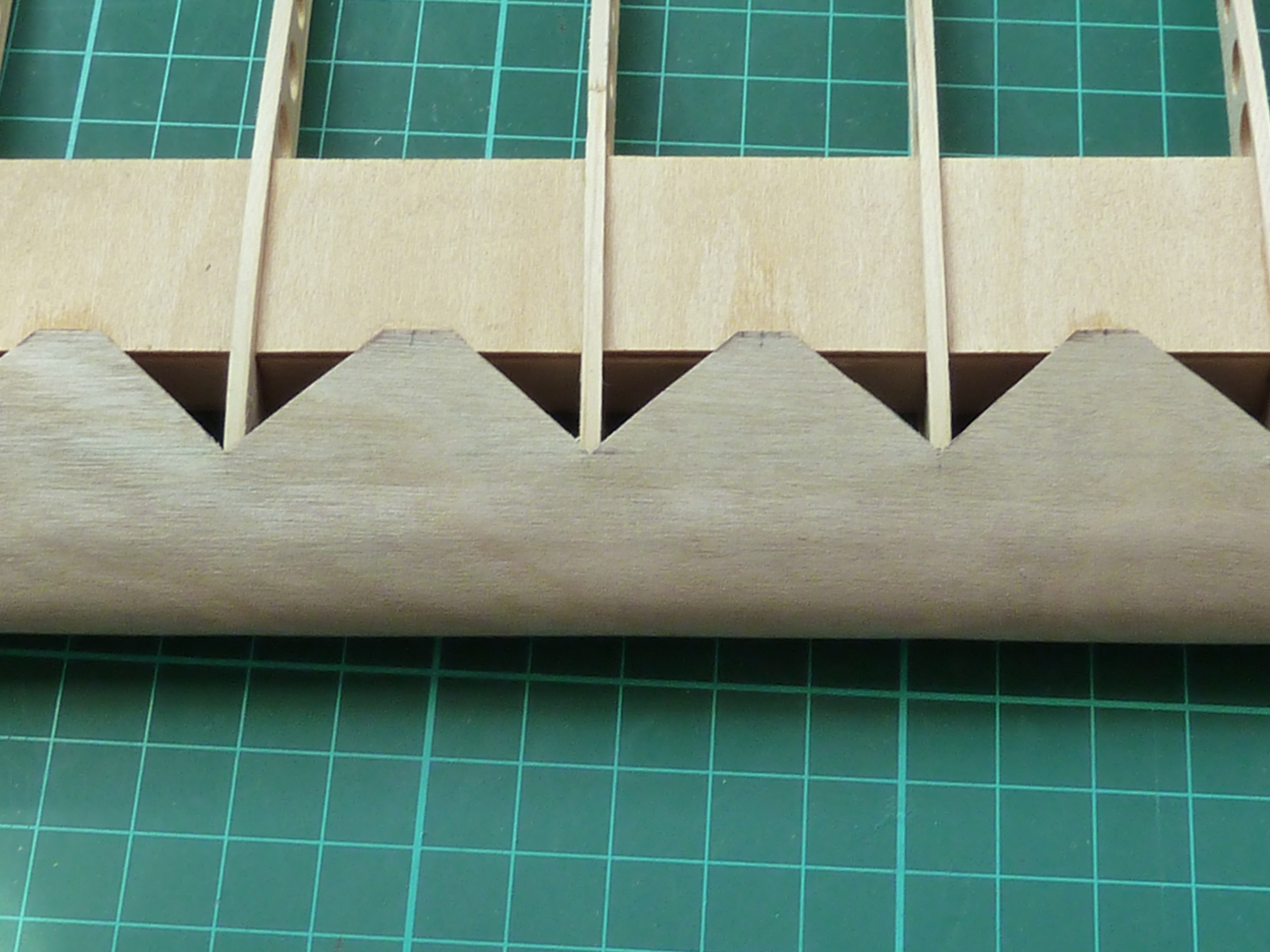
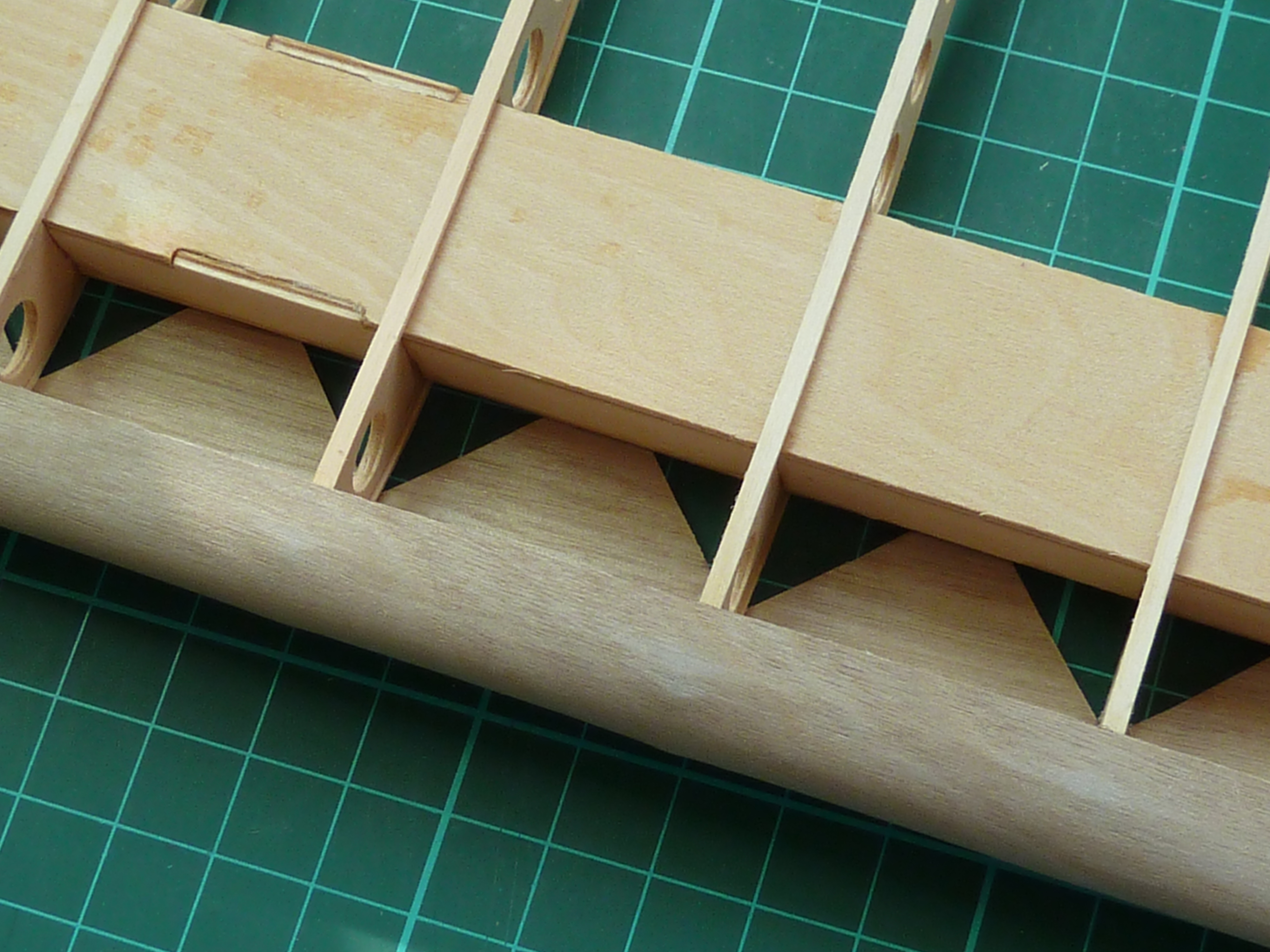
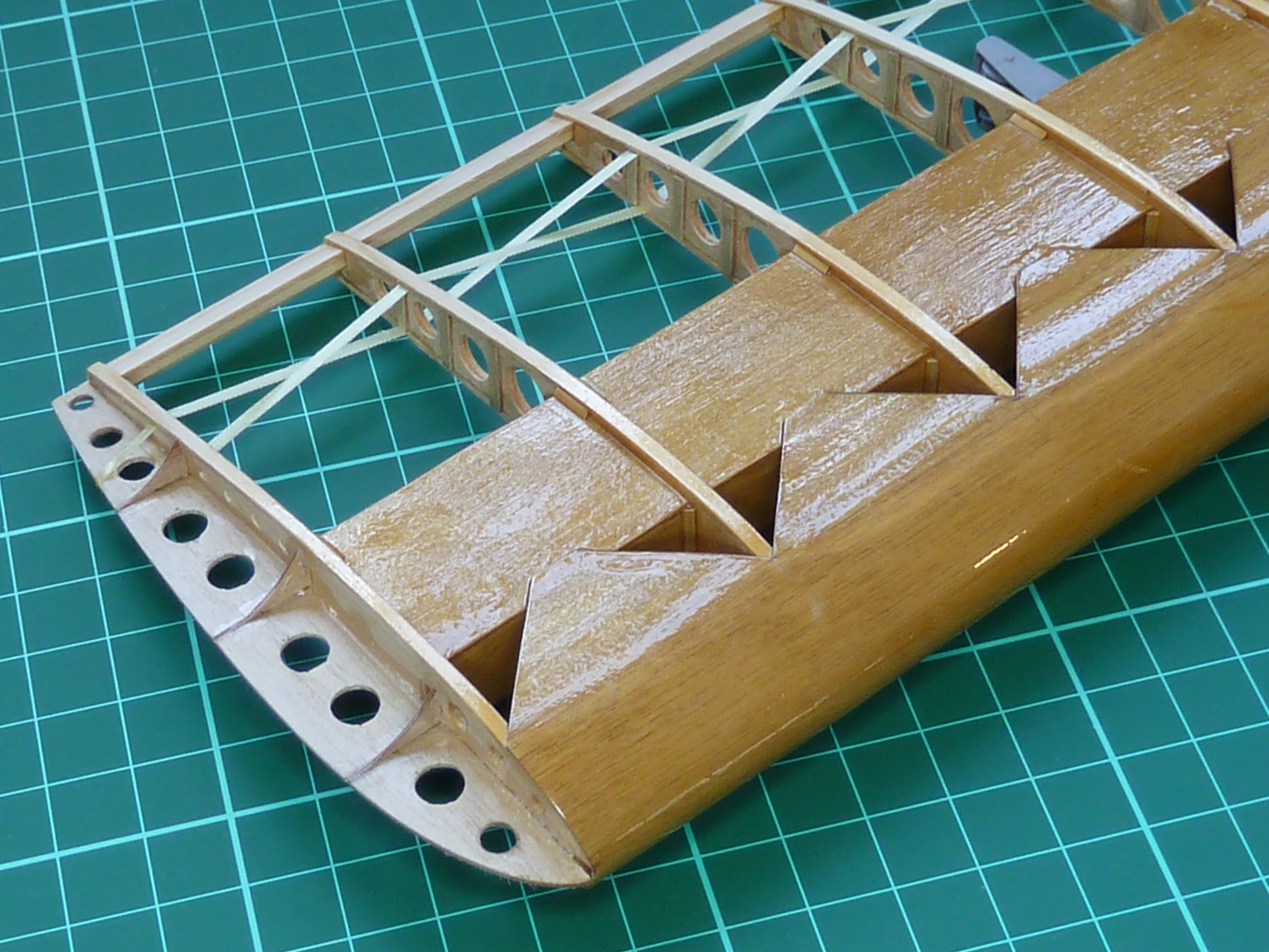
Aside from the out of scale plywood thickness and locating tabs there are two other main problems with the kit wing, and several detail ones. The first main problem is the wing tip which is plastic which I intend to replace with some scratch-built plywood parts, and the second is the leading edge. The latter bears no relation to the real aircraft at all. The Fokker was built with a 1.4mm plywood skin on the leading edge of the wing which wrapped around top and bottom. the top stretched back to the main spar where it was glued and pinned to it. The underneath was glued and pinned to the wing ribs and further held in place by straps midway between the ribs and going from the underside up to the point where the upper edge was pinned to the top of the spar.
Here’s a photo of the modified wing as it shows the difference much better than I can describe it.
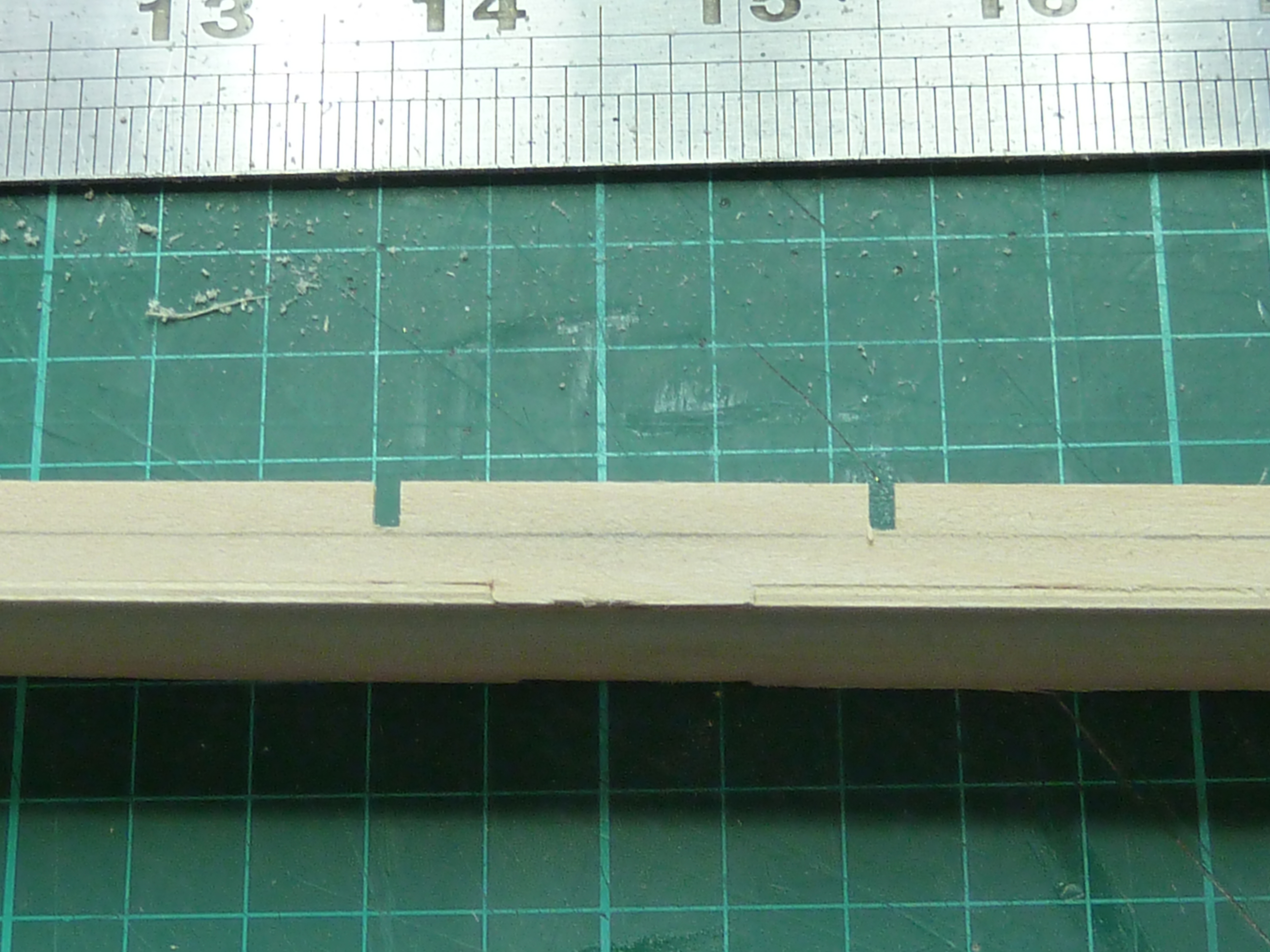
To replicate the real leading edge I used some 0.4mm thick plywood. Even at this thickness the curve around the leading edge is quite tight so to obtain the curve I soaked the plywood in near boiling water for a few minutes, then bent it around a suitably sized former made out of some dowel and plumbing tube while it dried.
The picture below is of a test piece I tried to prove the concept.

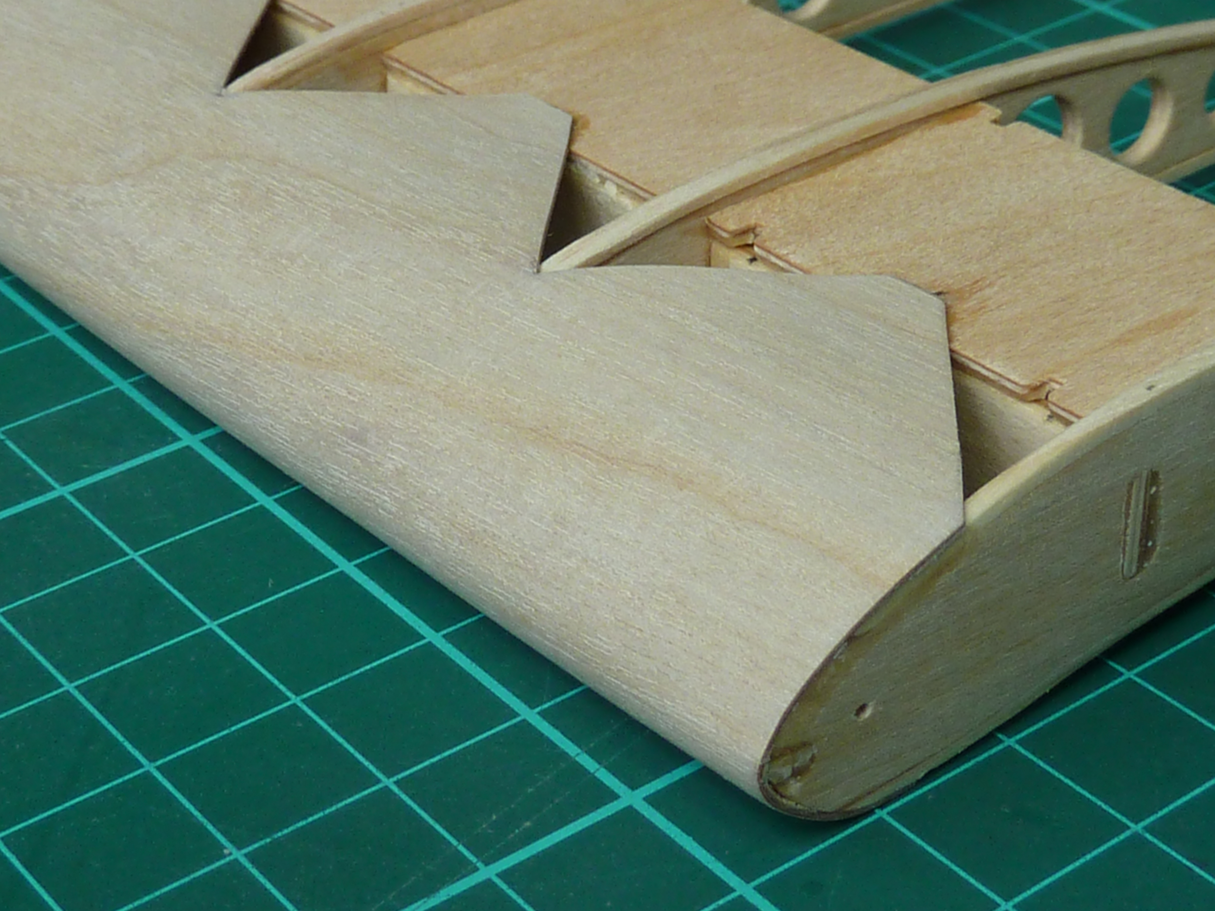
Having satisfactorily proved the idea I then set to making the real item. I ended up doing this 3 times. The first attempt had the upper triangles 180 degrees out of phase. The peaks were in line with the ribs, not between them. The second one was OK but I split the plywood while trying to get it to conform. I had the bend slightly out of line with the leading edge. The third attempt actually passed muster and I’m pretty happy with it. I certainly looks a lot better than the kit’s solution.
Prior to fitting the leading edge I also corrected a small problem with the wing root rib. This is placed too far outboard and leaves an unsightly gap to the fuselage, which may not be too obvious on a skeleton model, but would be blatant on a covered one.
So I broke off the existing wing rib and made a new one which I fitted slightly further inboard.
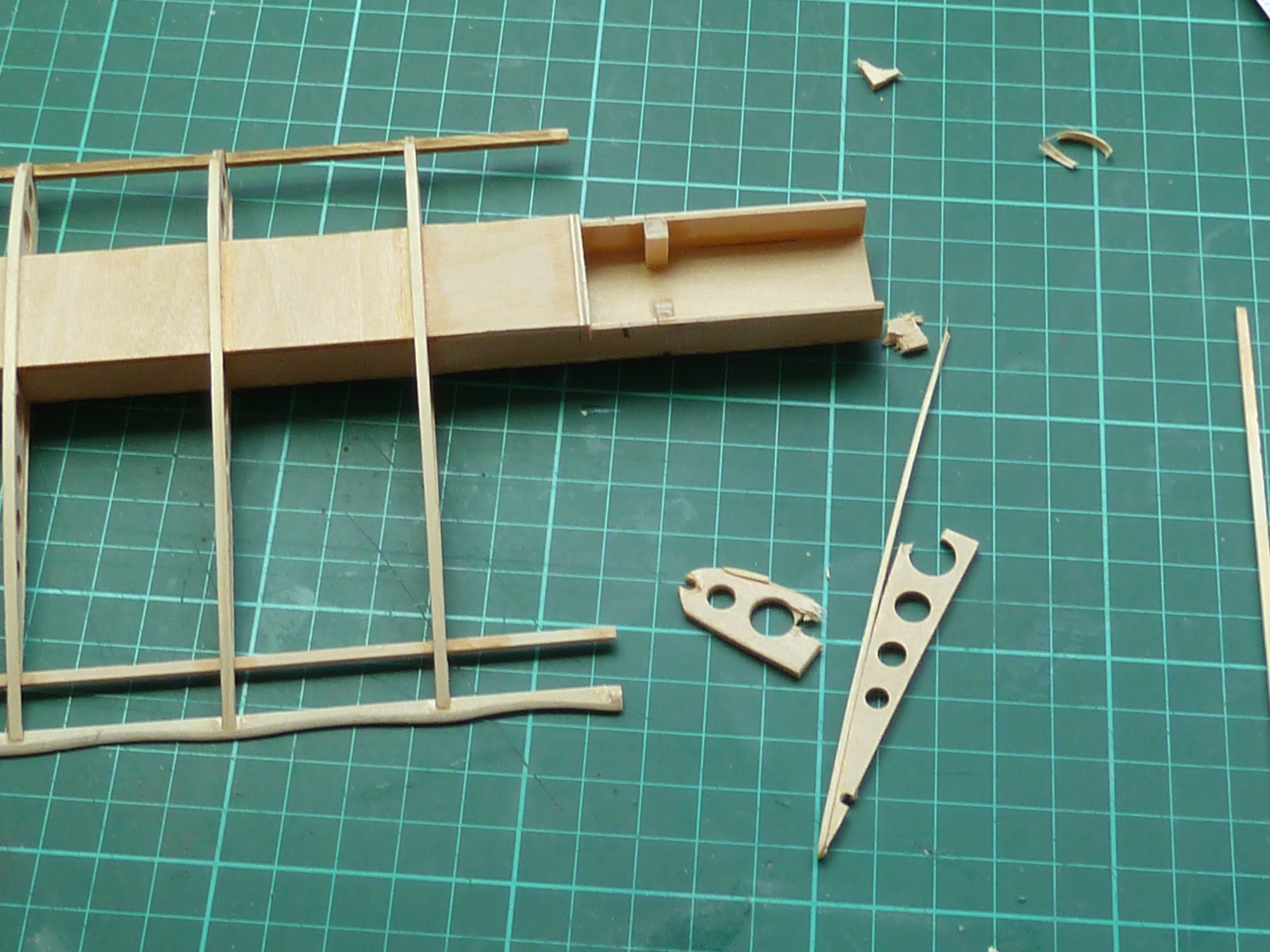
This rib has to take a dogleg and the forward part is canted slightly to miss the undercarriage struts as it did on the real aircraft.

The trailing edge of this wing is still inaccurate as it should be a thin wire and not wood. However, as I was covering this wing I stayed with the wood as it would be easier to cover and hidden anyway. Likewise there should be some vertical strengthening batons on the wing ribs, but again I didn’t bother as they would also be hidden.
The wing was finally given a coat of varnish to seal it and then covered with Solartex.

At the outer edge is the wingtip skid which is just dry fitted at this stage. I’ll fix it permanently after painting.
Having built the port lower mainplane the centre one followed the same route. the Upper mainplane was more involved as it would be half skeleton and half covered it needed to be made in one piece if an unsightly join at the centre was to be avoided (the other wing joins will be out of sight on the finished model).
This meant the issue of the out of scale plywood on the box section would need to be addressed. I did this by skinning the Hasegawa components with some of the 0.4mm plywood. A proper veneer would do the job, but I had the plywood to hand.
In order to keep the external dimensions of the structure the same, I slimmed down the height and width of the Hasegawa components by 1mm. 0.8mm for the two layers of external plywood and a little bit for the glue.
Before, with locating tabs.
After (well during really)

Front, rear and bottom covered. Only the top to go.
Hasegawa capping in place. Just the final plywood left to add.
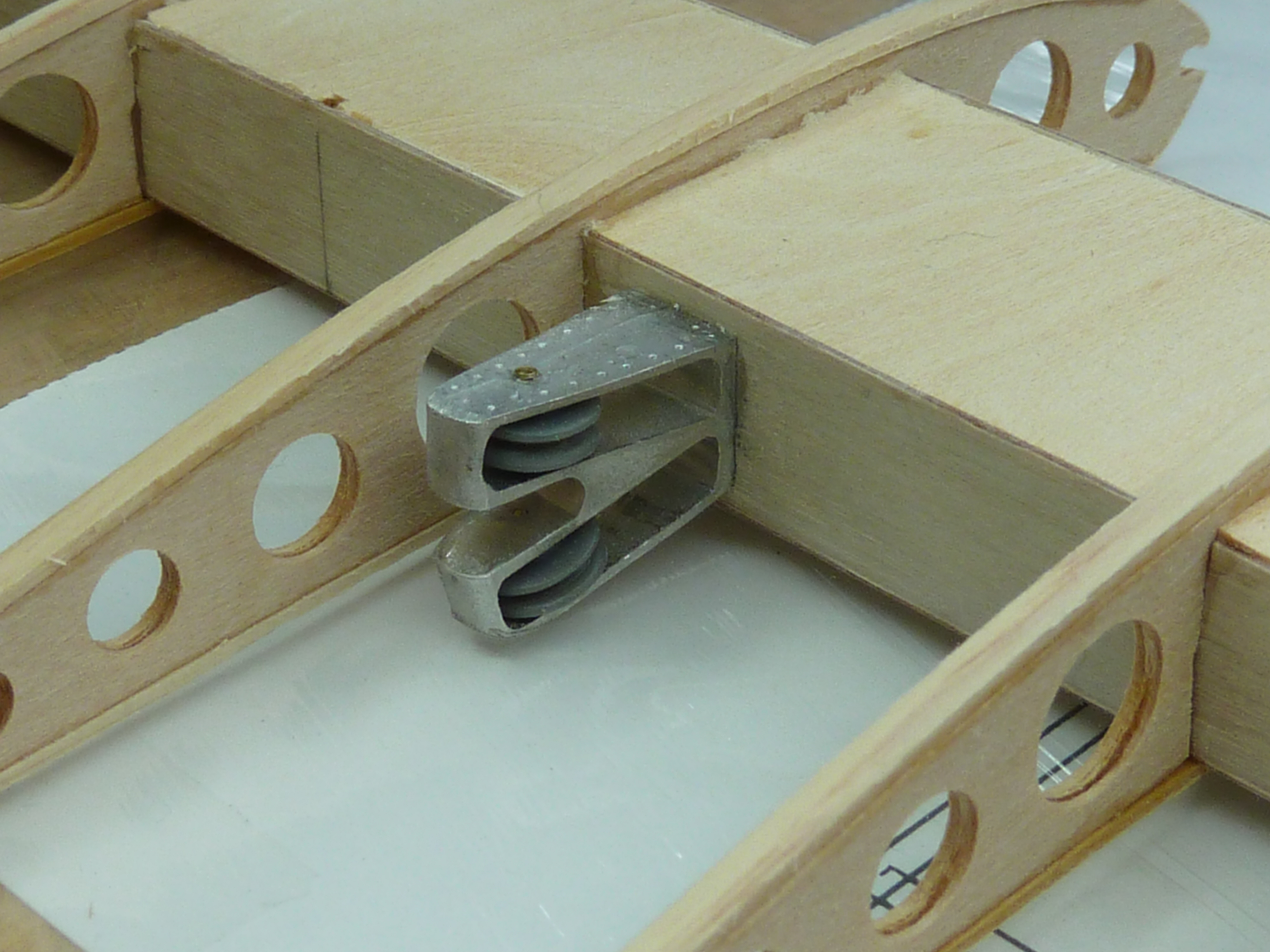
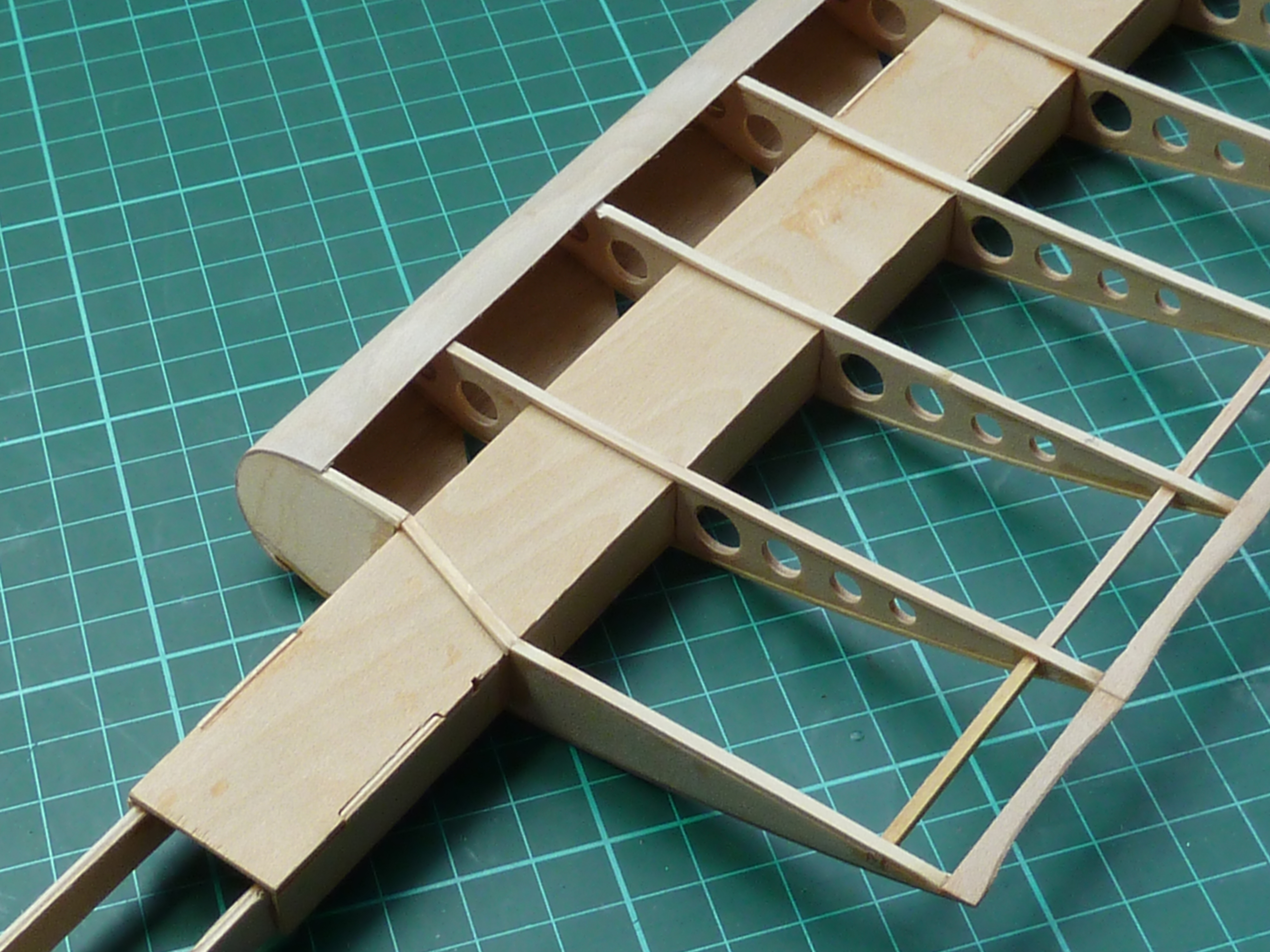
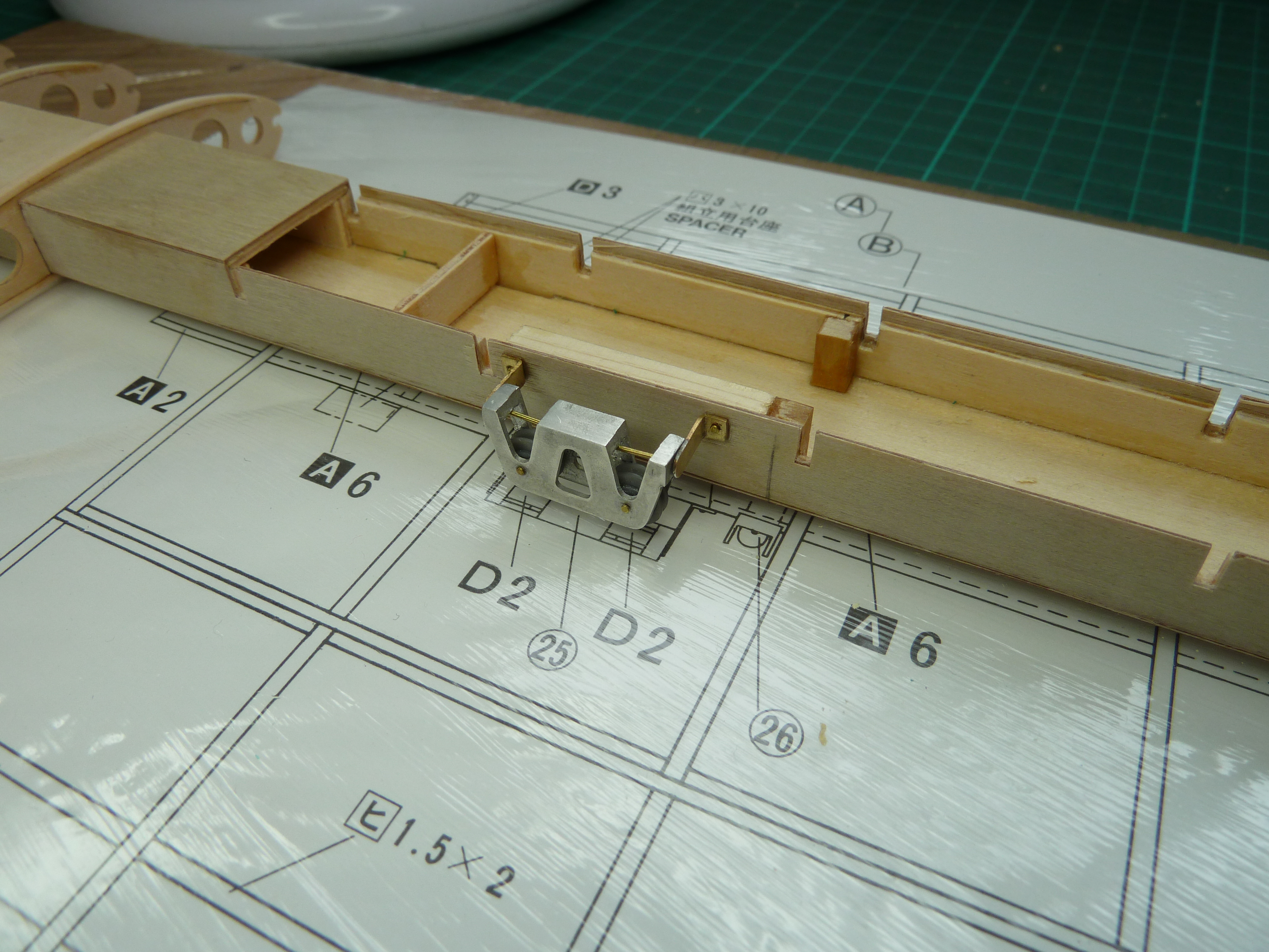
The latter two pictures show some of the guides for the control cables. The the first one gave me some grief as it was very slightly miss-cast and I had to build up the white metal with high tin solder to correct it. A bit nerve wracking as the white metal can disappear suddenly under your soldering iron if you get it too hot.

You can just see the repair in the above picture.
As the starboard portion of the wing would be visible I also added the strengthening batons on that side. These I did in batches to ensure they’d all line up on the finished wing.
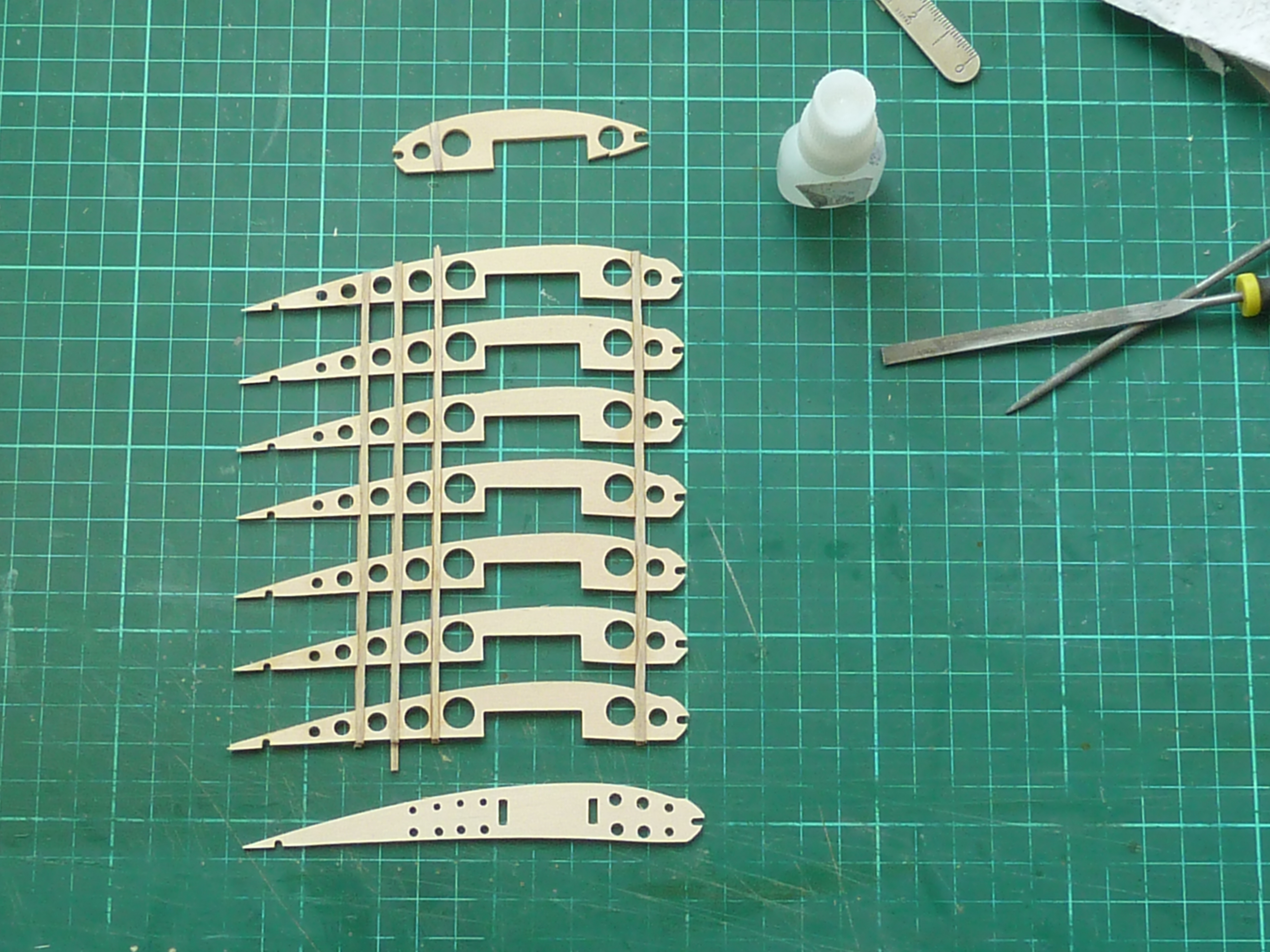
As an aside, I also modified the wind end rib at the bottom to add the lightening holes omitted from the kit.
A short aside on the batons:
When the DR.1 went into service initially it suffered from a number of catastrophic failures of the upper wing, and following several deaths, the type was withdrawn from service while the problem was investigated.
The investigation was carried out by the Ministry and attributed to the wing collapsing under torsional loads from the airleron during manouvering. The failures were put down to a number of issues, the main ones being: the wing design was fundamentally too weak and poor quality control, particularly in the application of varnish to the structure which allowed moisture ingress to weaken the glued joints.
A number of modifications were incorporated to overcome these issues, the strengthening batons on the wing ribs being one of them.
Above is a picture of the ribs installed with the vertical batons on them.
The skeleton wings also incorporate the strengthening webbing to stop the wing ribs flexing. the kit provides some black tape for this which is pretty heavy gauge and, though I have no proof of it, I suspect the original wasn’t black. So I opted to replace it with some 2mm silk ribbon in a cream colour. You can see it installed in the picture below, which also shows one of the modified wing tips in place.
Whilst the silk was a good idea in principal, I did find that the thin instant glue I was using wicked up the ribbon and left it looking a bit unsightly. You can see the effect on the leading edge strips shown below.

I’m not entirely sure how I’ll counter that yet. I may simply try painting the silk, but it makes a bit of a mockery of choosing the right colour etc.
To protect the wing from moisture, unlike Anthony Fokker, I gave it a good coat of yacht varnish, having already stained the leading edge and spar plywood with Liberon’s ‘Golden Pine’s wood dye so that it matched the rest of the structure’s colour.
That completed the wooden structure of the main wing. The trailing edge wires and airlerons have yet to the added, but I’ll do those when the rest of the starboard wings have been assembled.

That 0.4mm plywood leading edge,is that one continuous piece approx. 36 inches in length,or did you use two separate pieces of plywood,for the top wing? Thanks Again. Robin R.
LikeLike
It’s one continuous piece. I didn’t think I’d be able to achieve a seamless join otherwise.
LikeLike
There’s a product in the U.S. called Real Wood Paper, which is such a thin veneer that you can run it through your printer. I use the .010″ birch with fleece backing which bends beautifully around the leading edge, should you ever decide to abandon reason and do another Dr.1. 🙂
https://www.realwoodpaper.com/product-category/8-5-x-11/
LikeLiked by 1 person
Oh thanks for that. That might be very useful for another project I have in mind.
LikeLike