
As I’ve mentioned a couple of times before, my next model is of a nautical nature.
As I’ve never indulged in boat kits before, aside from some Airfix kits many, many years ago, I decided to start with something fairly middle of the road for me. The choice came down to either Amati’s Riva Aquarama, or Dumas’ Chris Craft 19ft Barrel Back. In the end I went for the latter, though subsequent research has shown that the Amati kit is probably better quality and not so different in price. The Amati may yet get built.
After sending off my pennies this duly arrived in the post, along with a few extras I’d already decided upon such as 2 channel radio control and a suitable motor.

The box is pretty heavy and packed with parts, along with a lovely wood smell. The kit I obtained seems to have been hanging around for quite a while as all the elastic bands holding the bundles of wood together had perished almost completely, but other than that it was fine.
The kit is a mixture of balsa, plywood, expanded PVC and mahogany planking for the exterior. A number of chromed metal fittings are also included along with vacuum formed seats and a number of transfer stickers.
Some of the wooden parts in the kit looked pretty rough to be honest, but they were accurately cut and will be hidden from view in the finished model, so that’s acceptable I suppose. However, there other areas in the kit where quality has been compromised in order to contain costs to unacceptable degree for me. I’ll address those as I come to them in the build.
Assembly starts with tacking the sheerwater parts to a flat MDF assembly board.
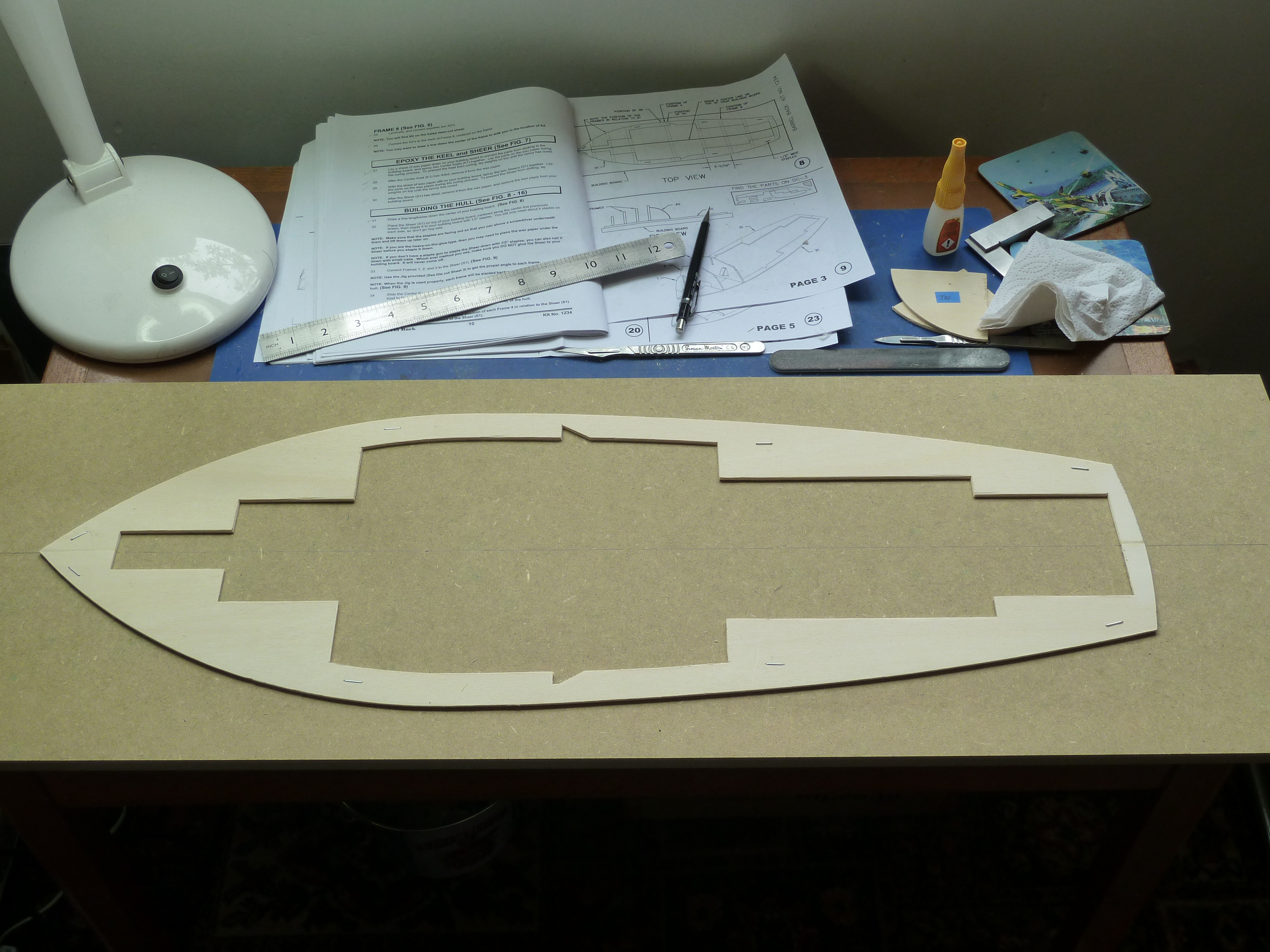
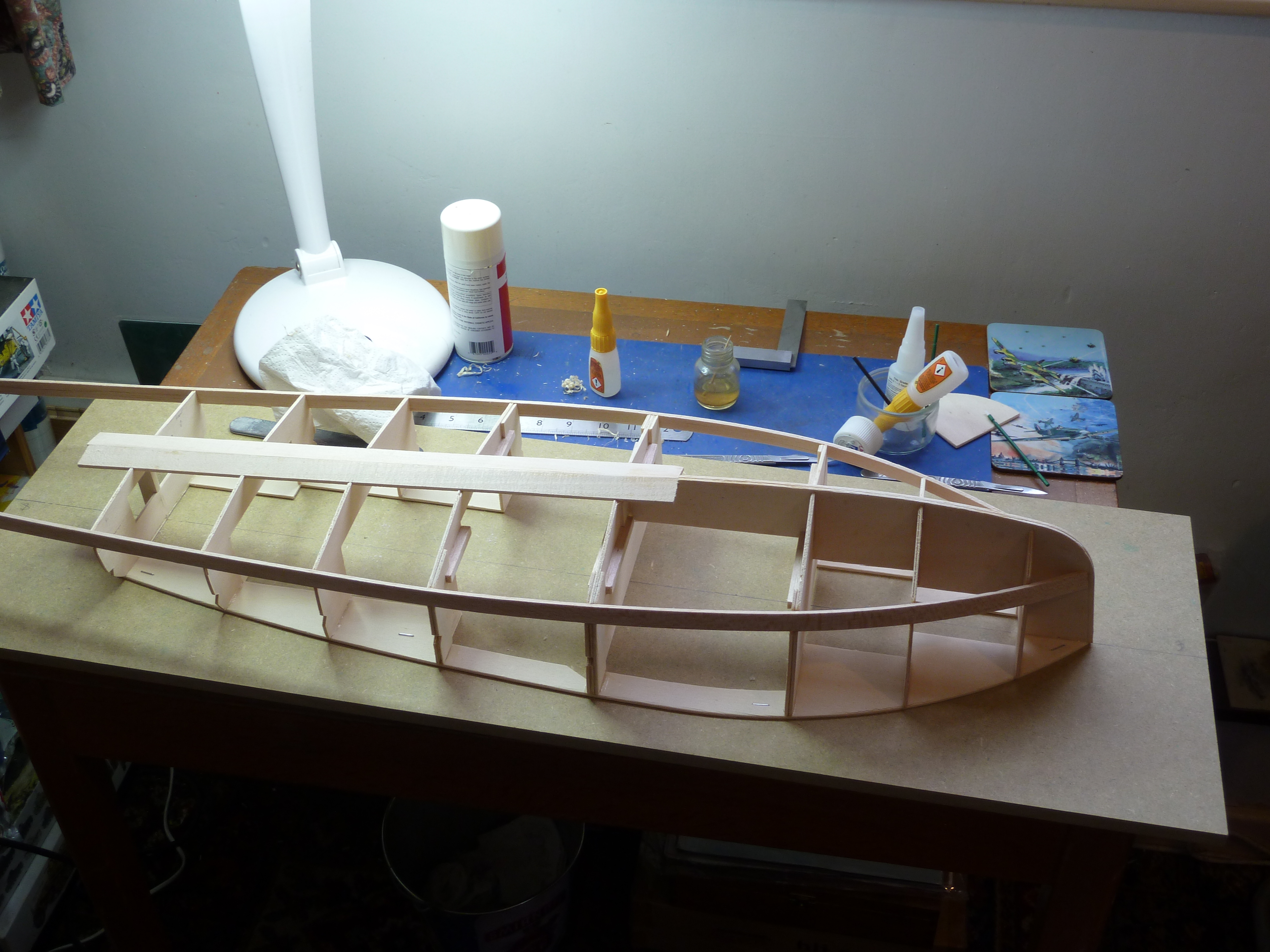
The keel and main structural frames are then attached to this using an angle template provided. I glued all of the parts using thick superglue, because life is too short to wait for epoxy.
One thing I should mention is that the fit of the forward part of the keel in some of the frames is very loose indeed. In fact the rearmost one’s slot wouldn’t even touch it, it was that wide. I had to glue some supporting blocks on either side to bridge the gap. It’s not a major issue at all and is easily resolved, but it did leave me wondering what I’d done wrong for a while. So if you make this kit bear that in mind.
Once the frames were in place the whole affair was covered with pre-cut expanded PVC sheet. The bottom sheets being thicker than the sides as the kit is designed to require planking on the sides and top only.
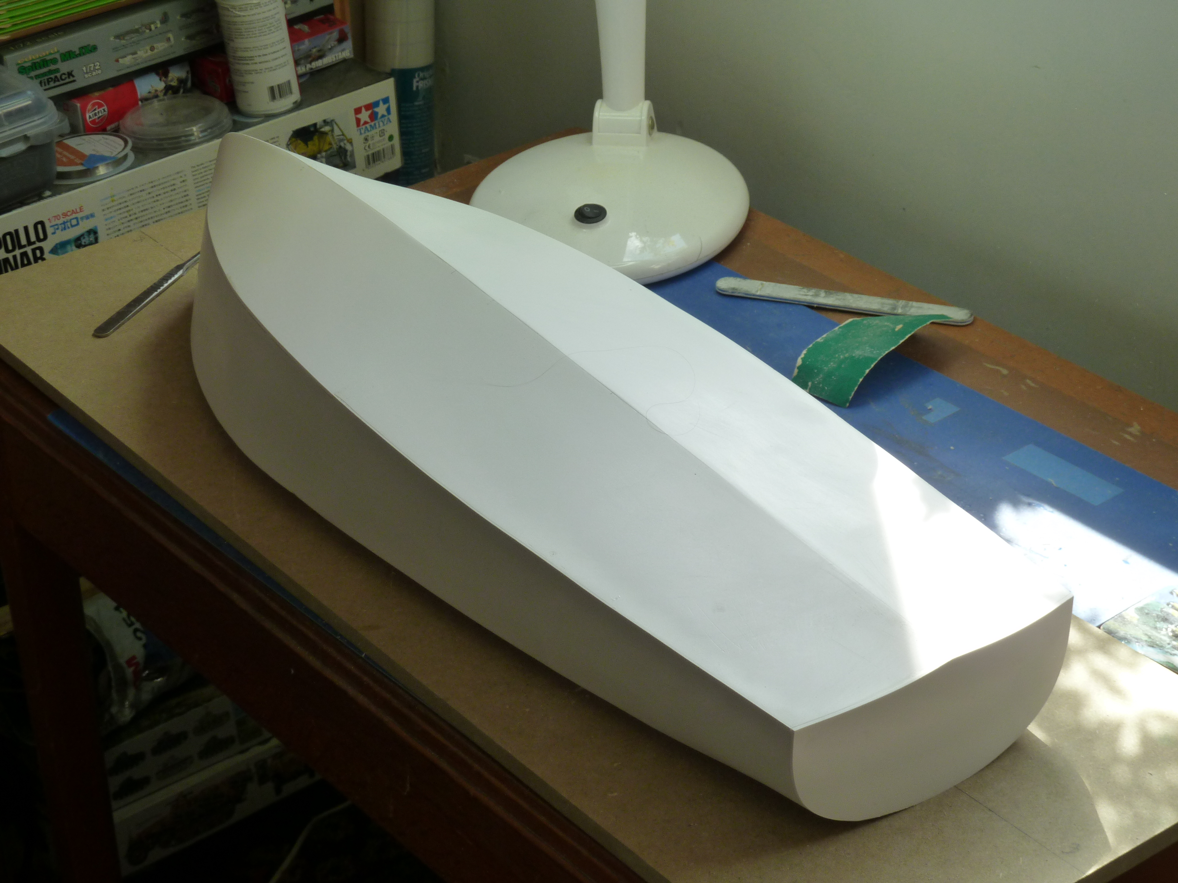
I’m new to this nautical lark, but the system seemed quite good to me and the build’s progress was pretty rapid to this point. Only a few days were required to get something looking distinctly boatish.
Persuading the PVC sheets to conform to the exact shapes needed a fair amount of force at times, and despite the parts being pre-cut I still needed to indulge in a fair amount of trimming and fettling to get a decent fit, and even then I had to fill some minor gaps with glue. Superglue accelerator was a must at this stage to make sure the parts were properly fixed before letting go of them.
Next up was the assembly of the engine bay cover. This is built in-situ with foil, in my case, used to stop the parts being inadvertently glued to the main frame. The method ensures that the panel is a good fit.
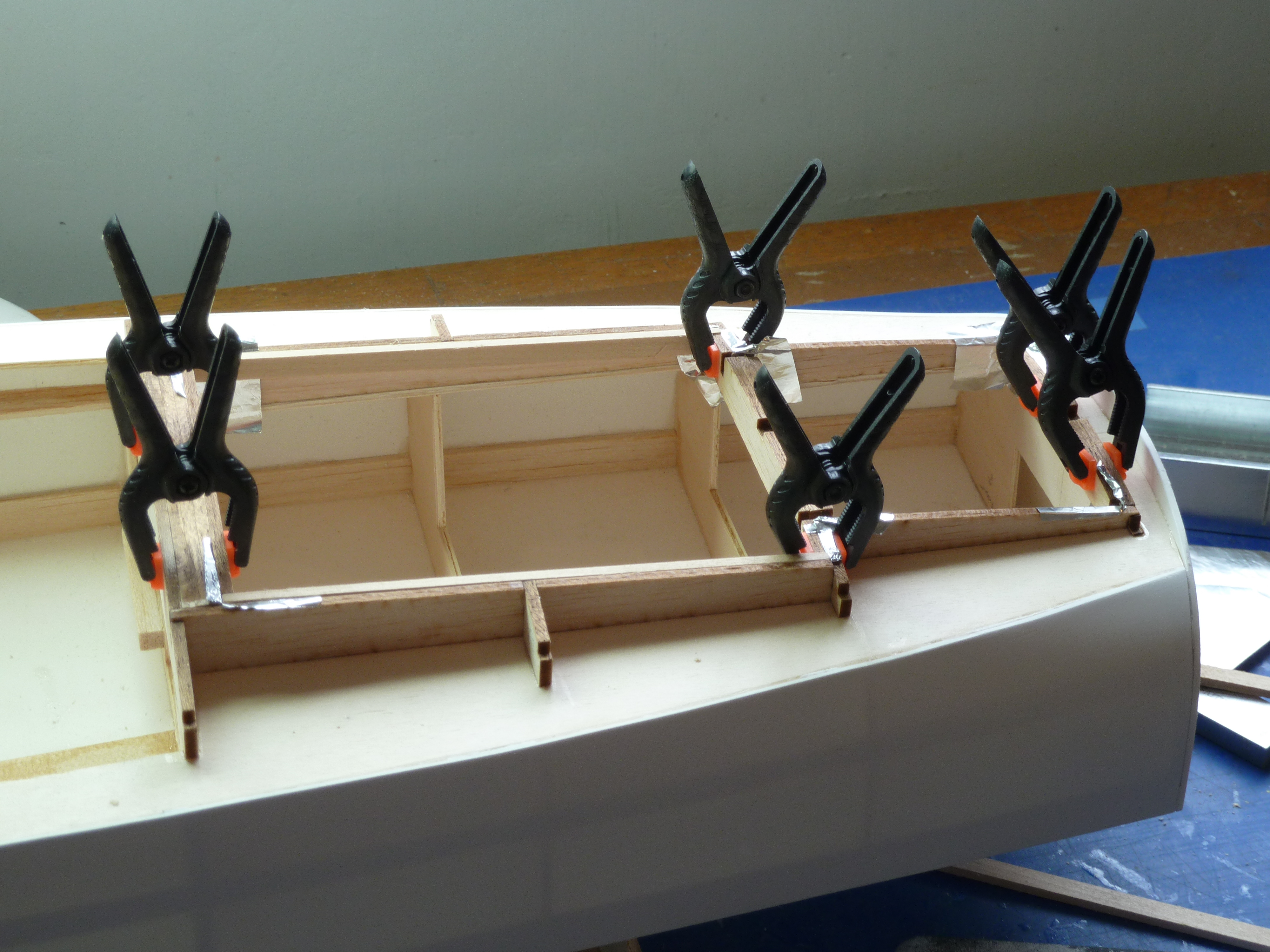
However, the top surface of the finished frame is covered with more sheet PVC and this has to be attached off the model. Here’s the assembled cover with the first strips of mahogany planking in place.
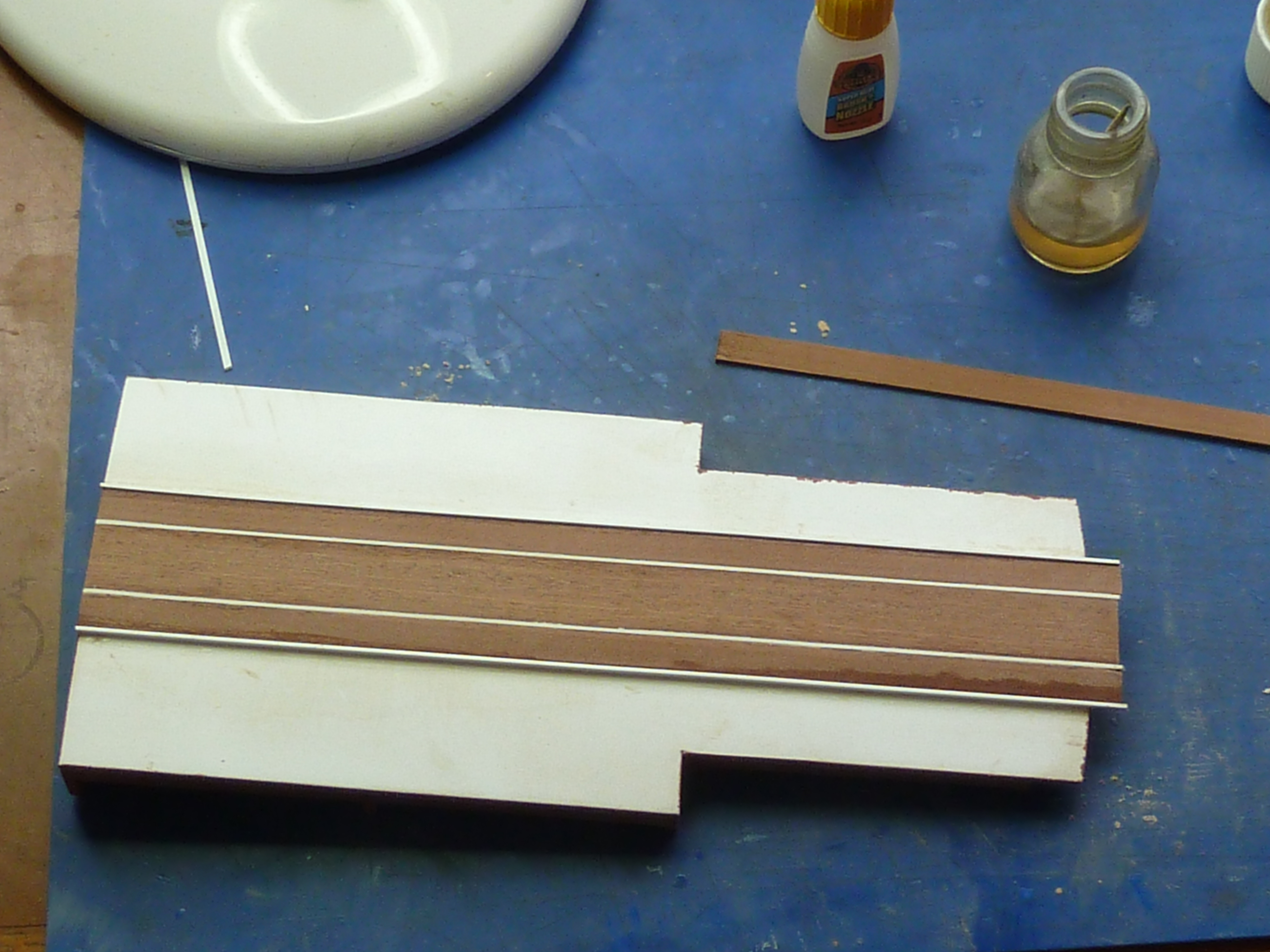
It was a bit out of sequence to be planking the thing at this stage, but I wanted to get an idea of how easy, or hard the operation was. The answer was, that it is easier than I expected. Just take care with lots of test fittings and it’s not too hard. The main problem for me was the amount of glue I got on my fingers.
The white stripes between the mahogany planks are simply strips of white polystyrene by the way.
The finished item is shown below.
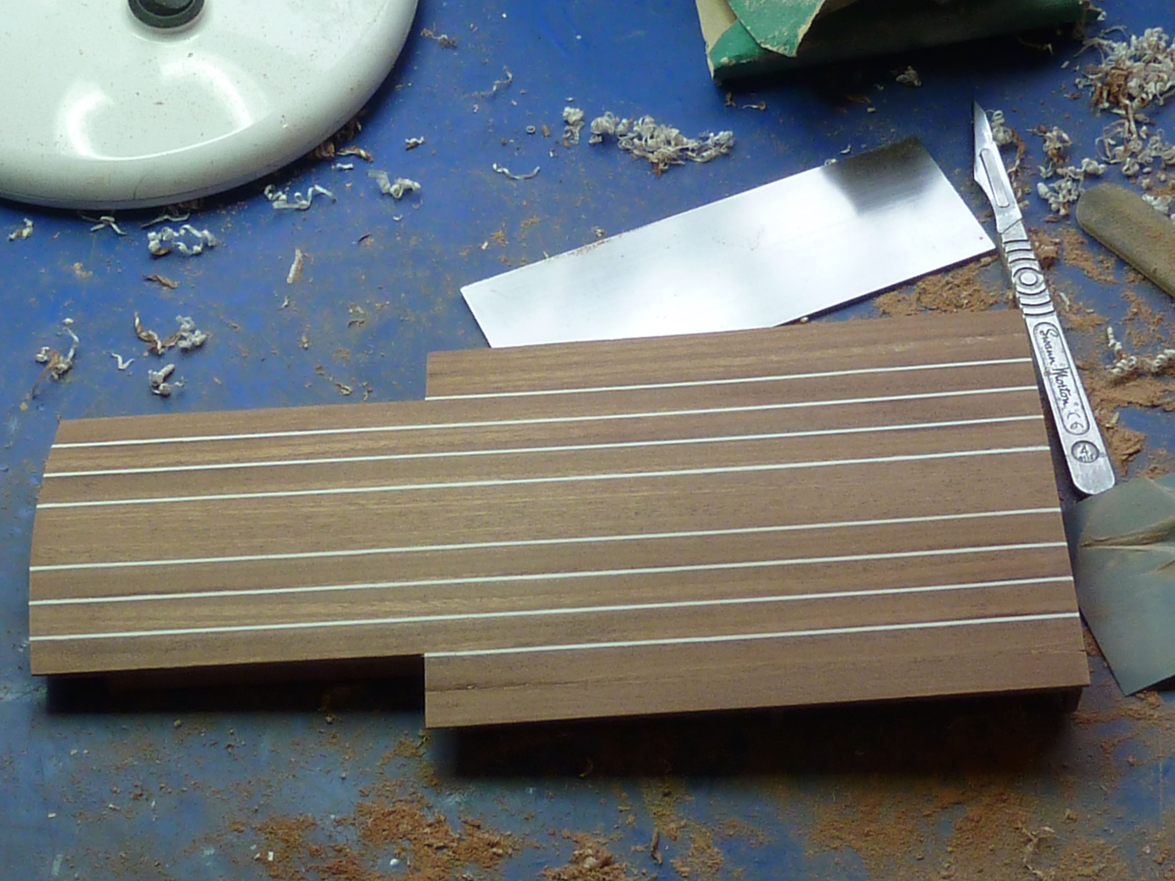
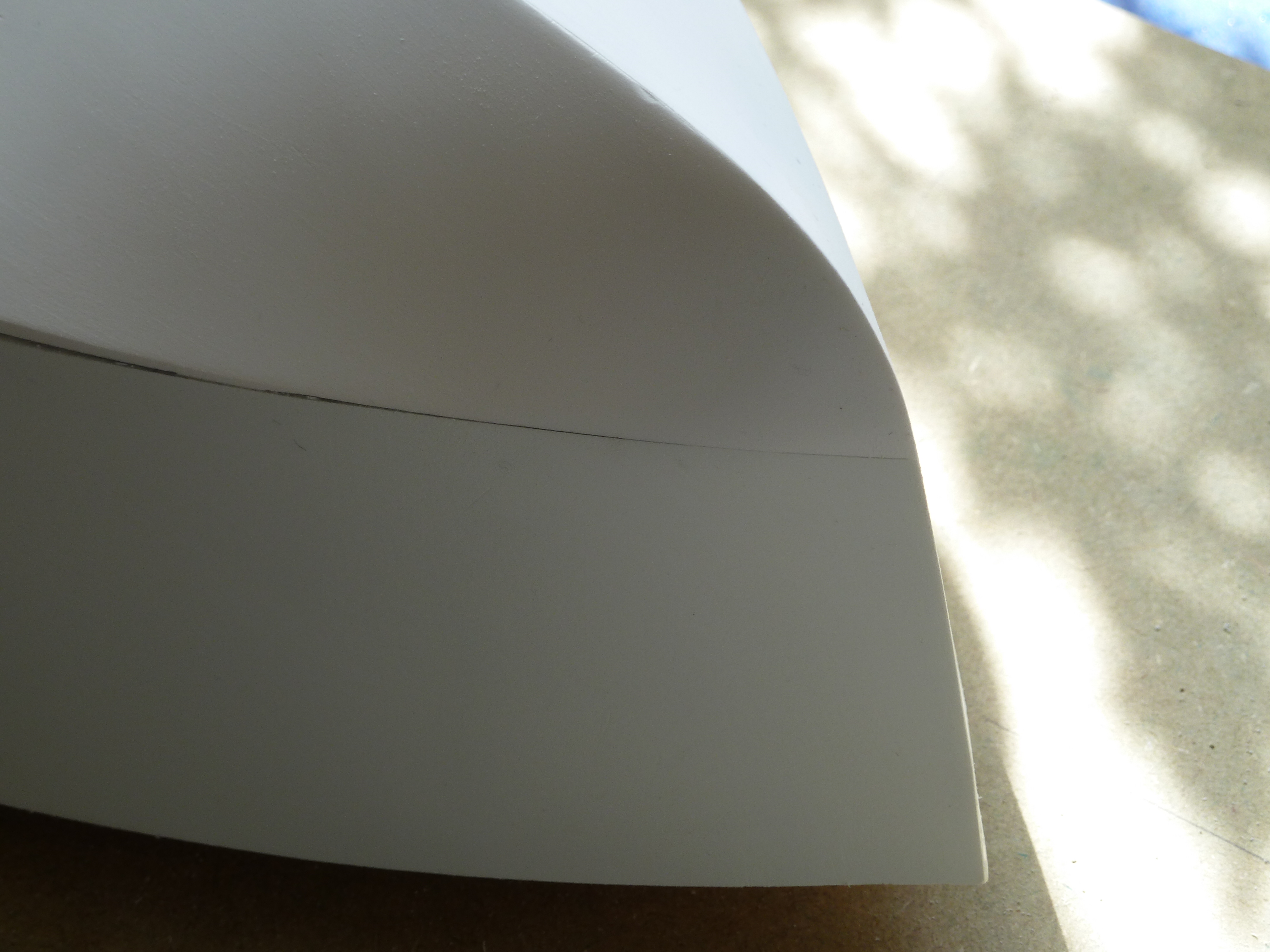
And close up (of one of the best bits of course).
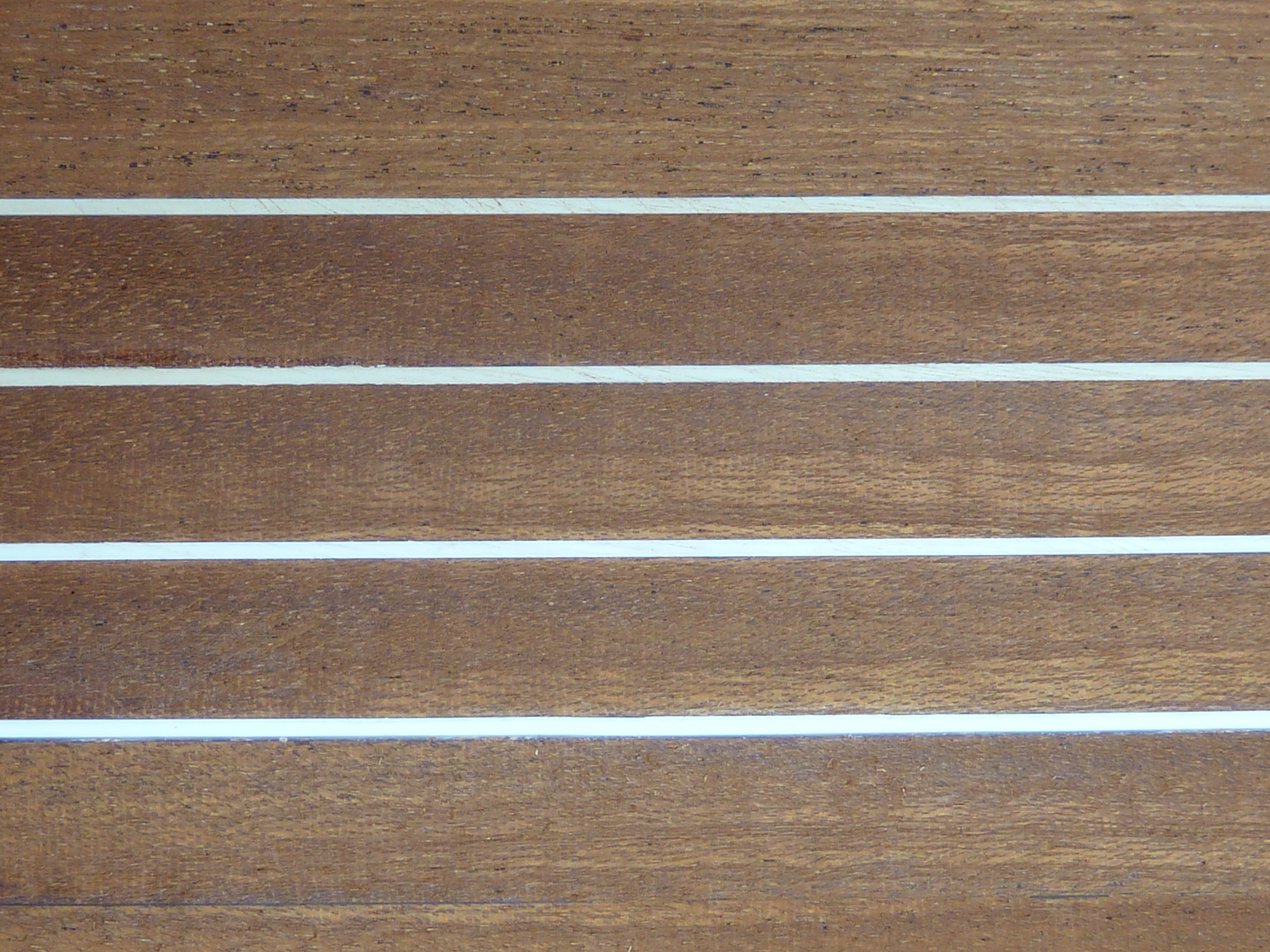
Incidentally, the bottom polystyrene strip in the picture has been cleaned up to remove the sanding marks. The others still await cleaning.
At some point between removing the frame from the model, fixing the PVC and planking it the whole assembly warped very slightly, such that I couldn’t get a flush fit both front and back at the same time. The deformation was only about 1mm though so I hoped that I could sort out way of fixing it later. The instructions are also a bit vague on how the access panel is supposed to be held in place. Perhaps I missed something, but it seemed to me that there was nothing to locate the thing vertically other than friction in the aperture. Likewise nothing held it securely in place.
I’ll have to go back and see if I’ve missed anything later on in the instructions, but the whole locating and fixing thing seems to come under “and then a miracle occurred”.
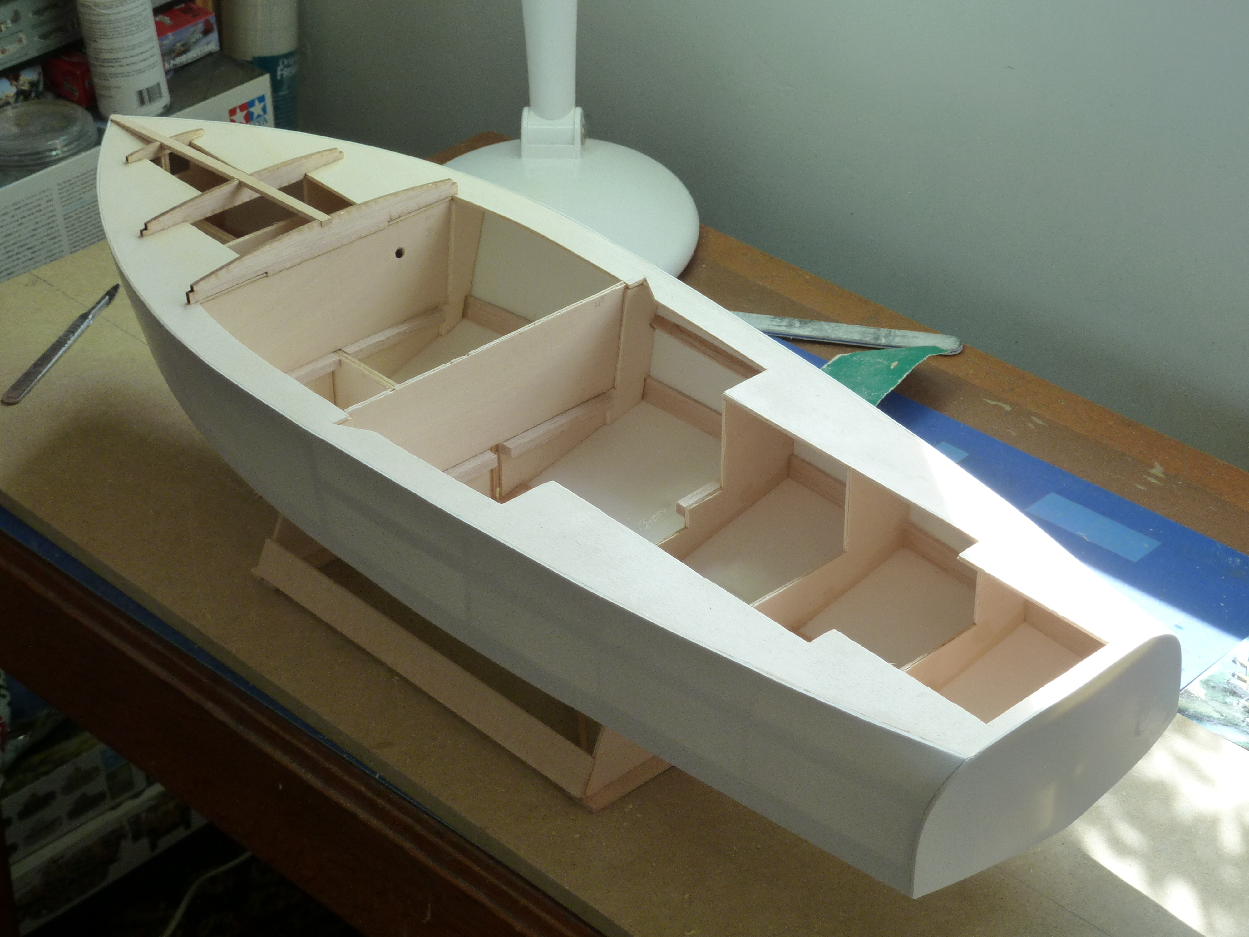
With the main hull structure completed it was time to assemble the cockpits. These have to be done early in the build as you can’t get enough access once the decking is in place.
The kit’s solution is pretty basic compared to what I’m used to and a world away from the real thing. I assume it’s because most RC modellers are more interested in sailing the thing than building a fully detailed model.
Here is a picture of a real boat’s interior hosted on www.classicboat.com.

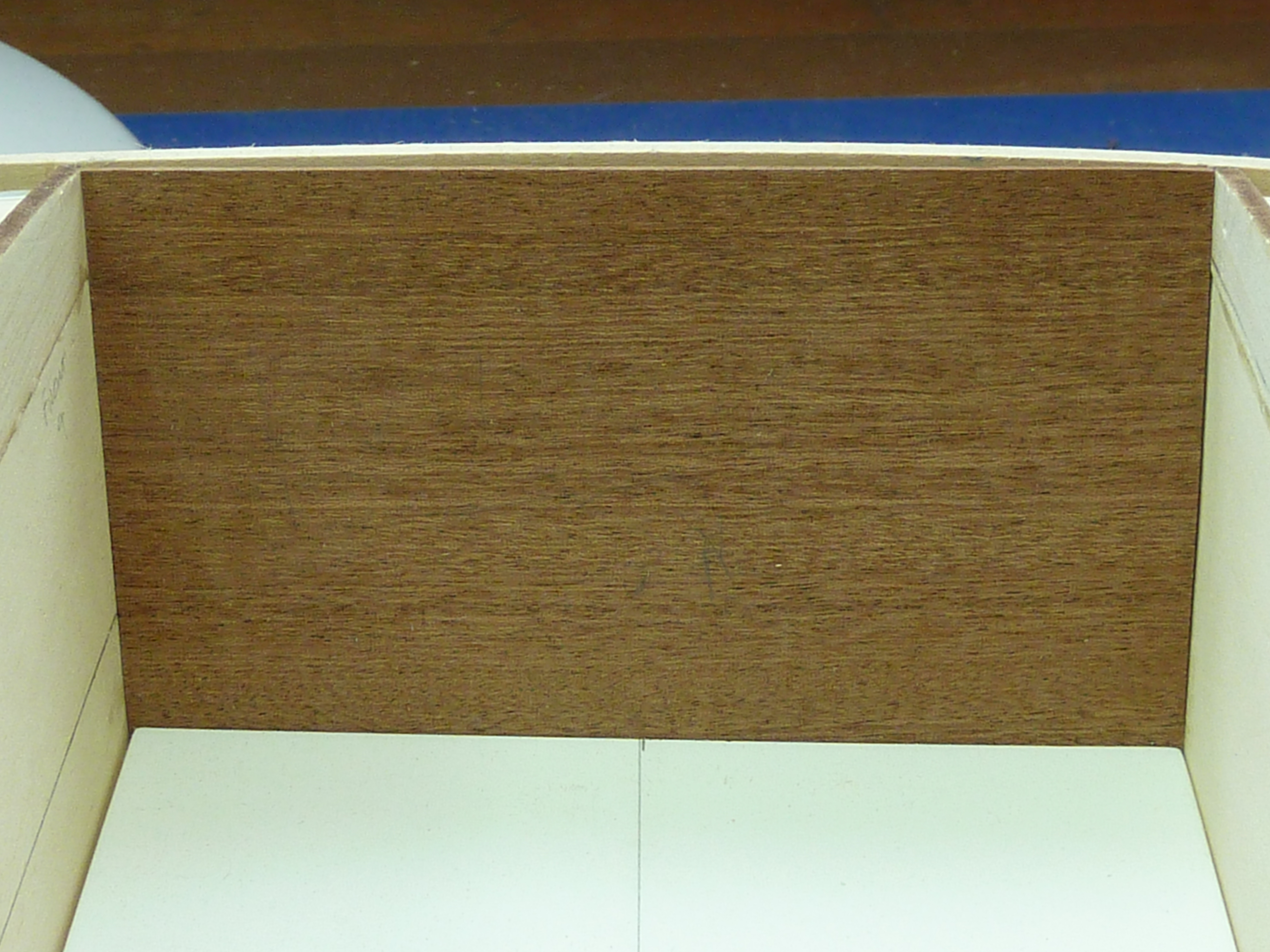
This is how the side panel appears in the kit.
I decided to add a bit more detail to the side panels taking the real boat picture as my cue.
The plain side pieces were cut into three, mounted on a small frame to hold them together, and a hole cut in for the glove box.
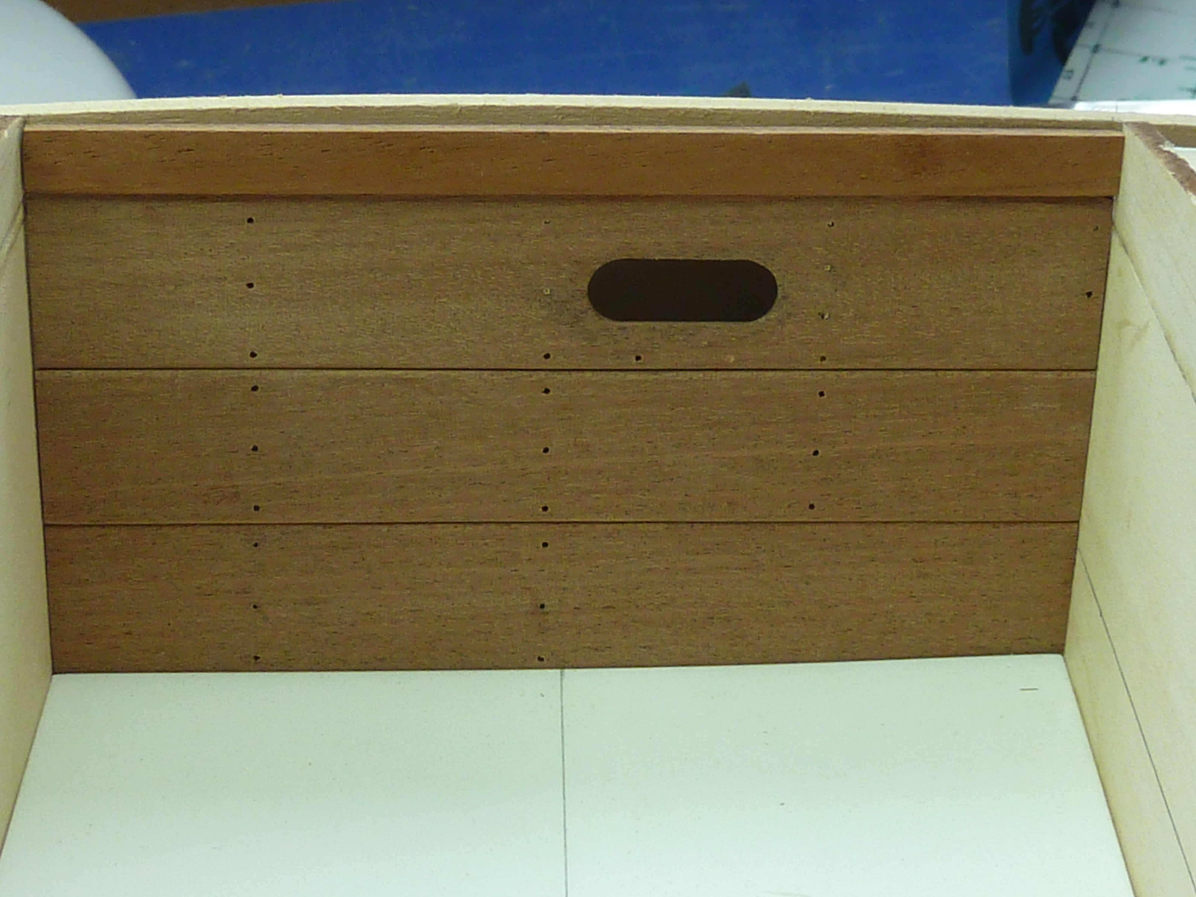
The fixing screws were simulated with 1mm stainless steel rod sanded flush to the surface.
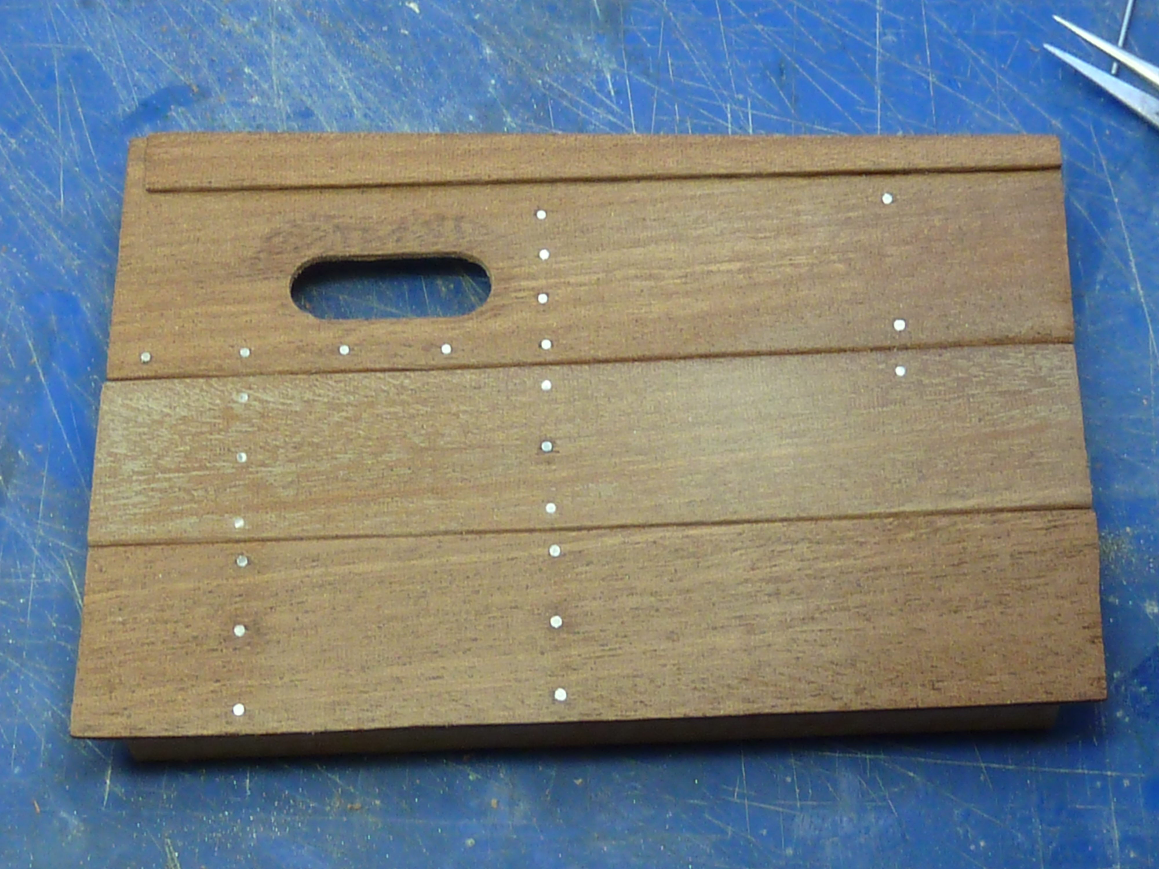
I was quite pleased with the result.

The glove boxes were fabricated from plasticard.
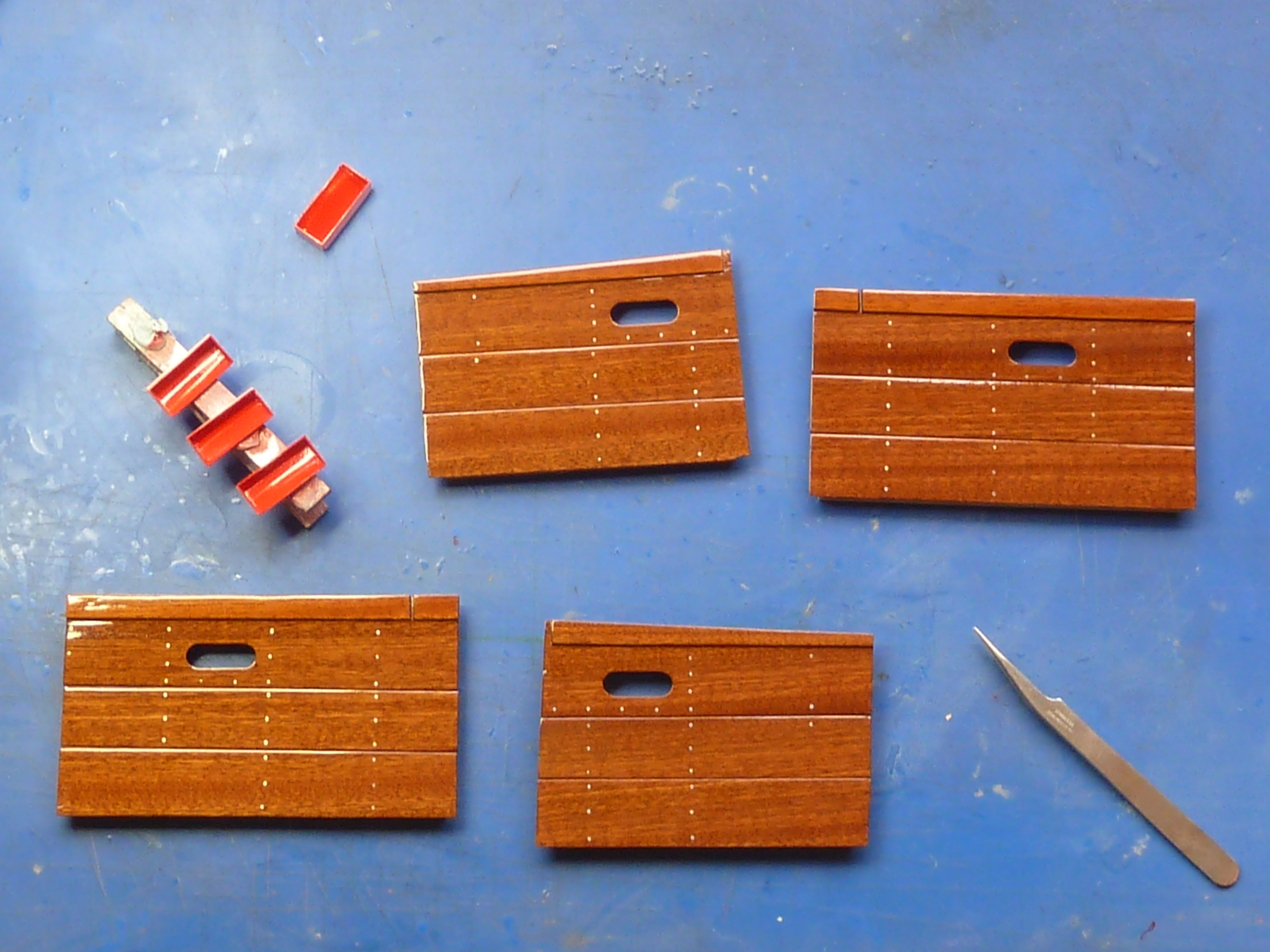
Here is the finished panel in place.
Which brings me onto the seat saga…
The seats in the kit are vac formed plastic ones and, again, pretty simple and toy like, so I decided to make my own from scratch.
The basic shape was cut from balsa block and then a thin layer of Polycell crack filler smeared on top and left to dry thoroughly.
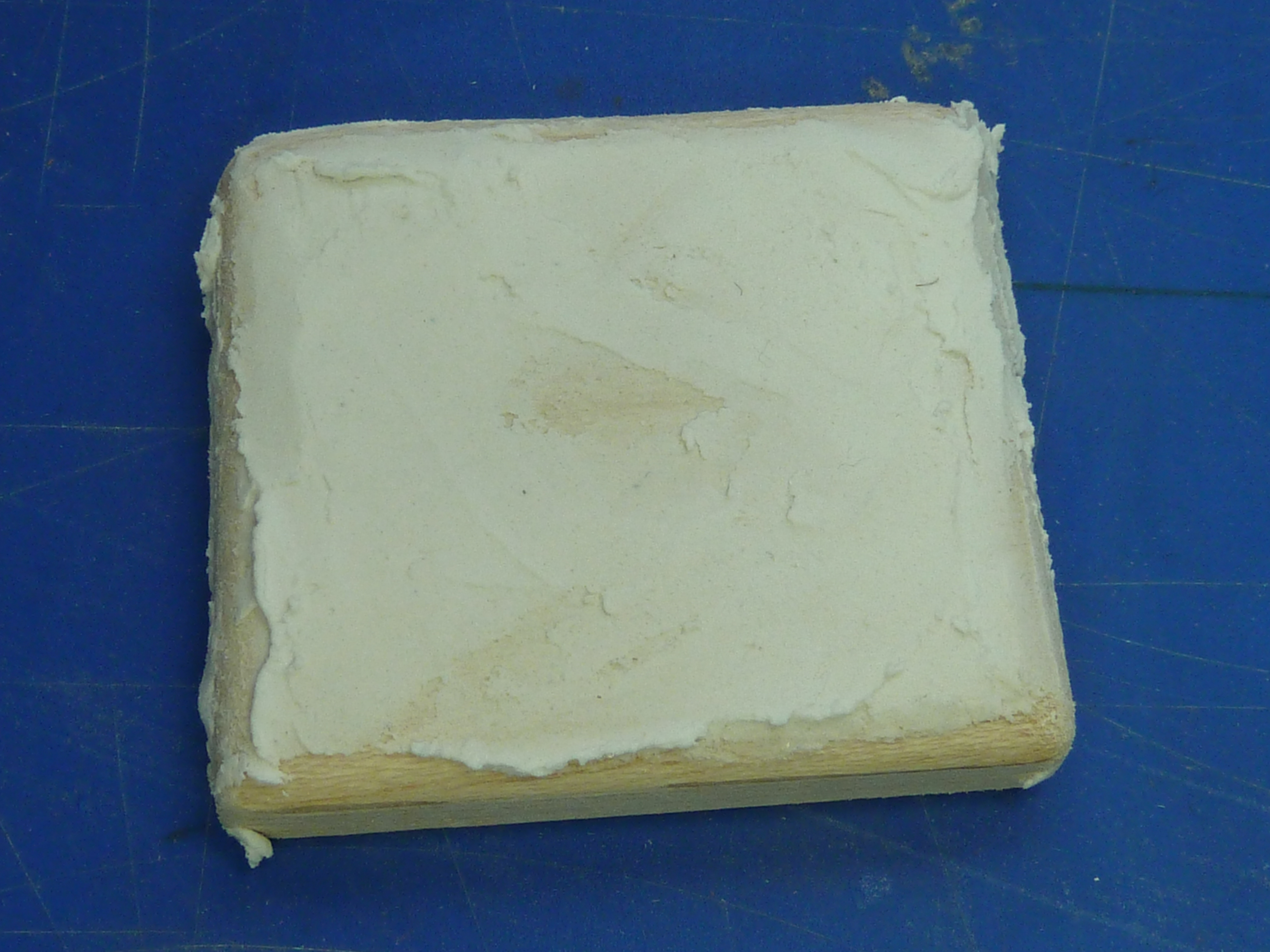
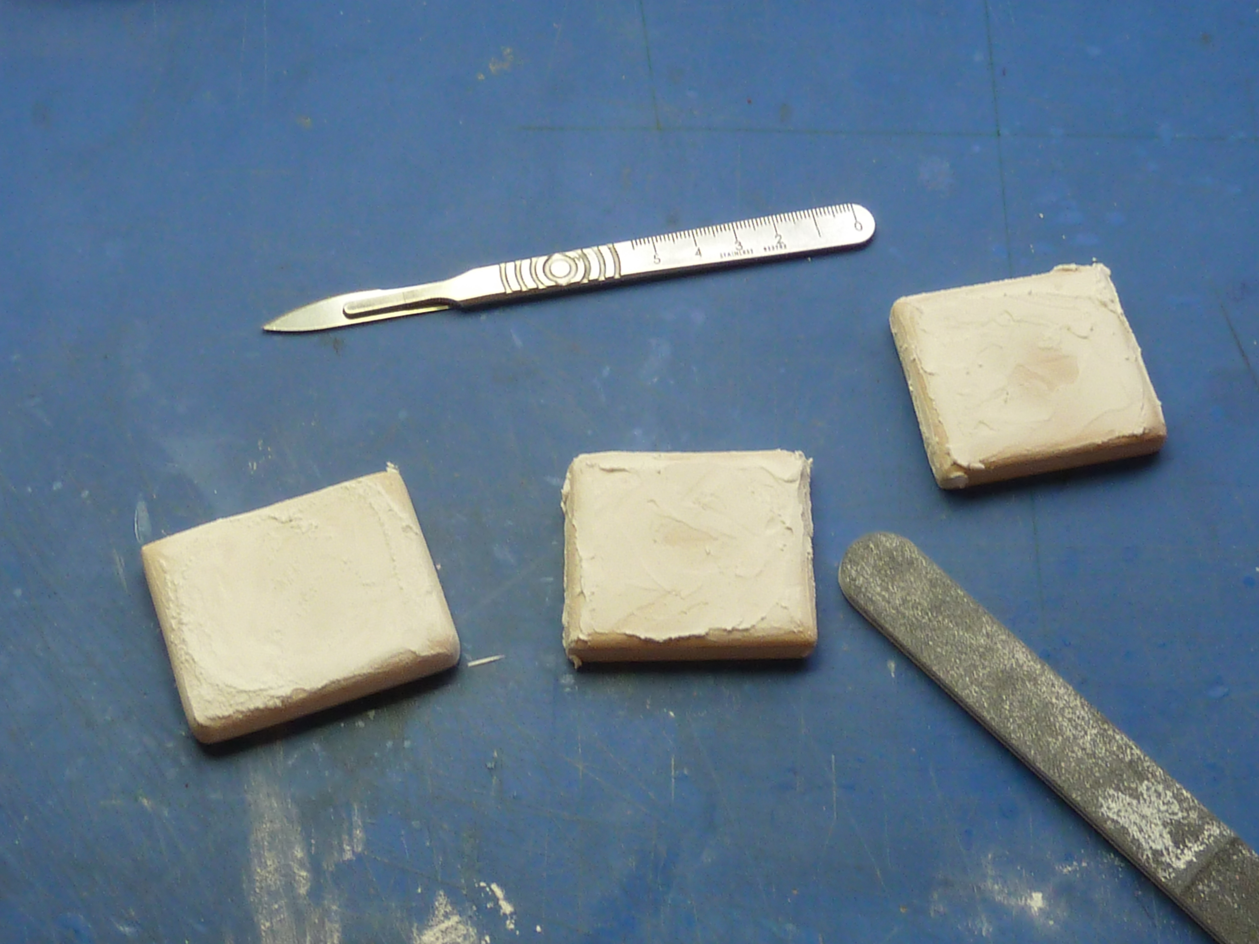
Once dry, the surface was sanded smooth and sculpted with a dip in the centre plus a few random wrinkles added around the edges. The piping at the edge of the cushion was made from thin solder glued in place with superglue. Super glue was also used to fill in the gap between the wire and the main cushion.
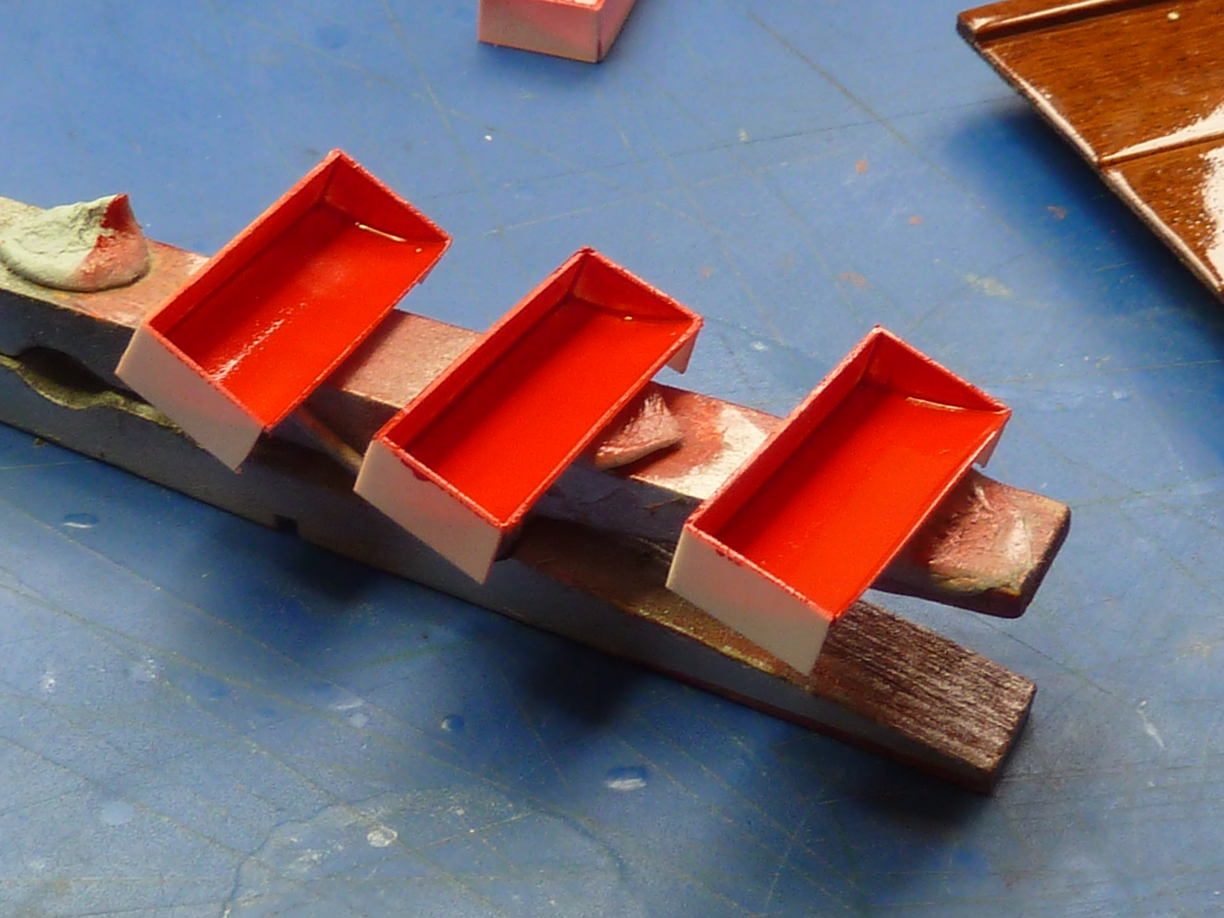
The whole affair was then sanded smooth (again), sealed with high build primer and an acylic gloss applied, simply because it gave a nice smooth finish for the final paint. A picture of one of the scratch built seats is shown below, next to the kit’s for comparison.

The seats were then given a coat of white primer and the final red colour. To protect the red, a final satin varnish was airbrushed on top.
Here are the finished seats prior to installation. I should point out that scratch built seat bases were also knocked up to suit the new arrangement.
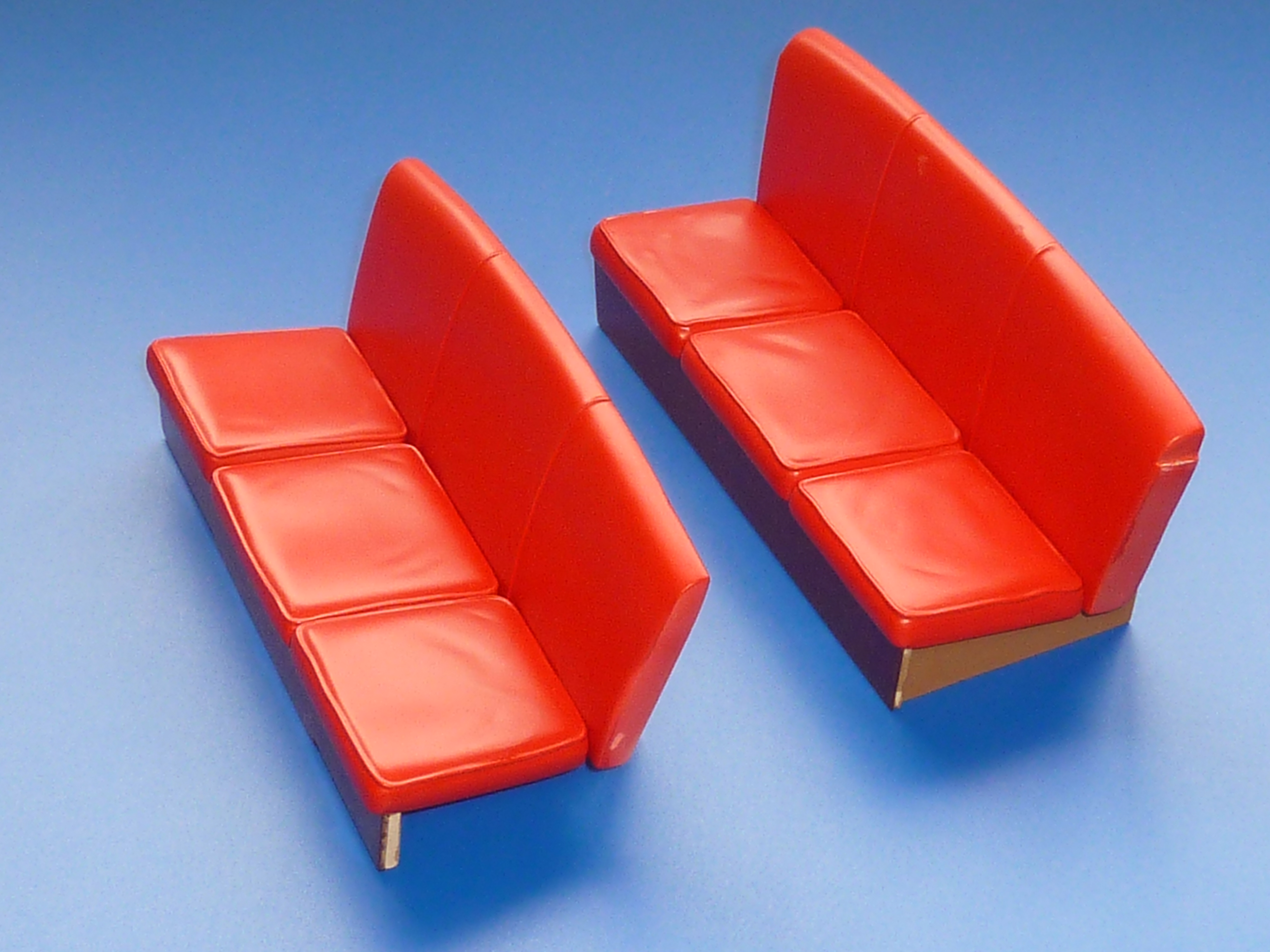
The finished items are so much better than what is provided in the kit.
The next area which received attention was the main instrument panel. This is an item that everyone will look at in the model so I wanted it to have some impact. The kit’s offering fell way short of what was required.
The instruments and dash trim, that you can see in the real boat picture above, are simulated in the kit with a simple sticker.

You can see it in the middle of the sheet above. I was not impressed.
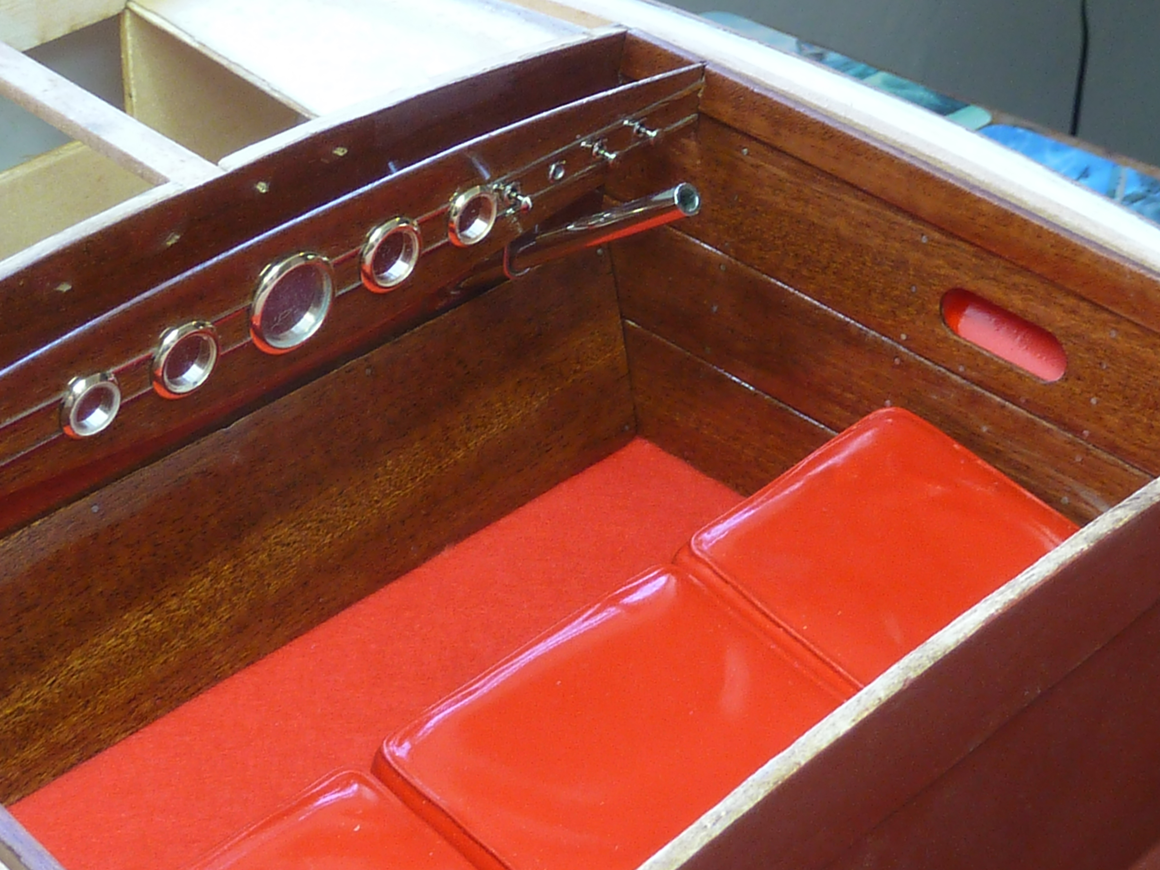
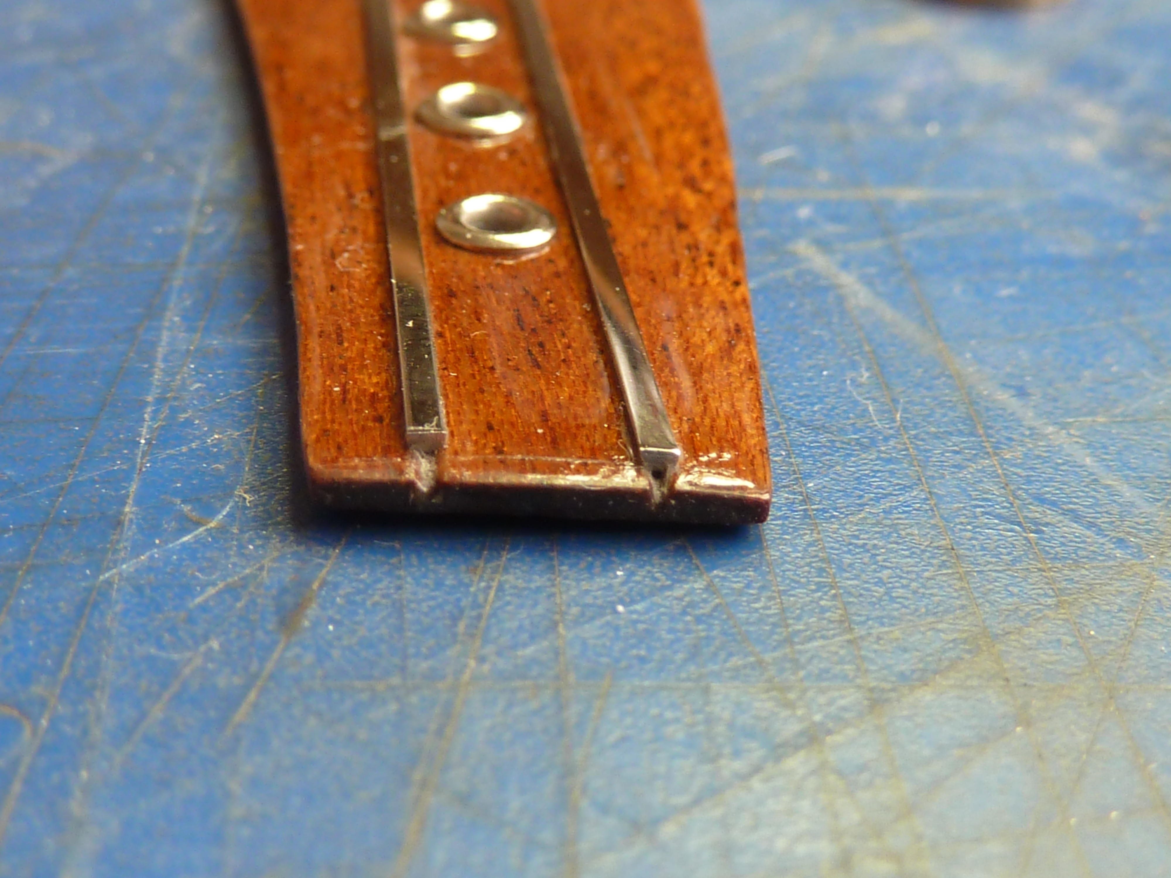
The first thing to do was to find something that would do as instrument cases. I don’t have a lathe so I needed something that I could buy in. After a fairly lengthy search on the net I finally found some glazed portholes which were close to what I wanted. They were a little thick in the rim and were brass but it was the best I could come up with. I did think about trying to nickel plate the ‘bezels’ but that’s a skill I haven’t perfected yet, so I left them as they were.
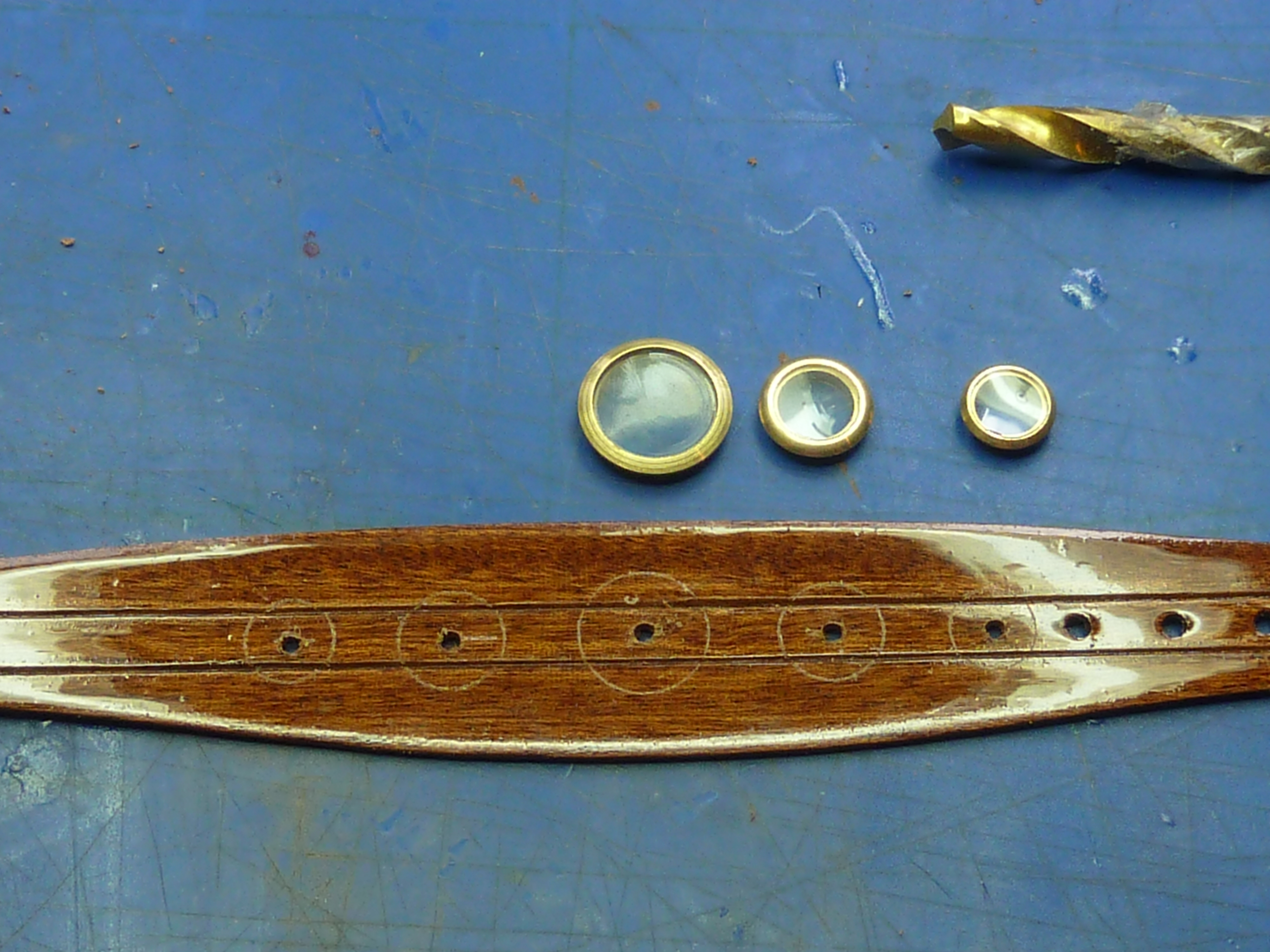
The sizes are 12, 8 and 7mm.
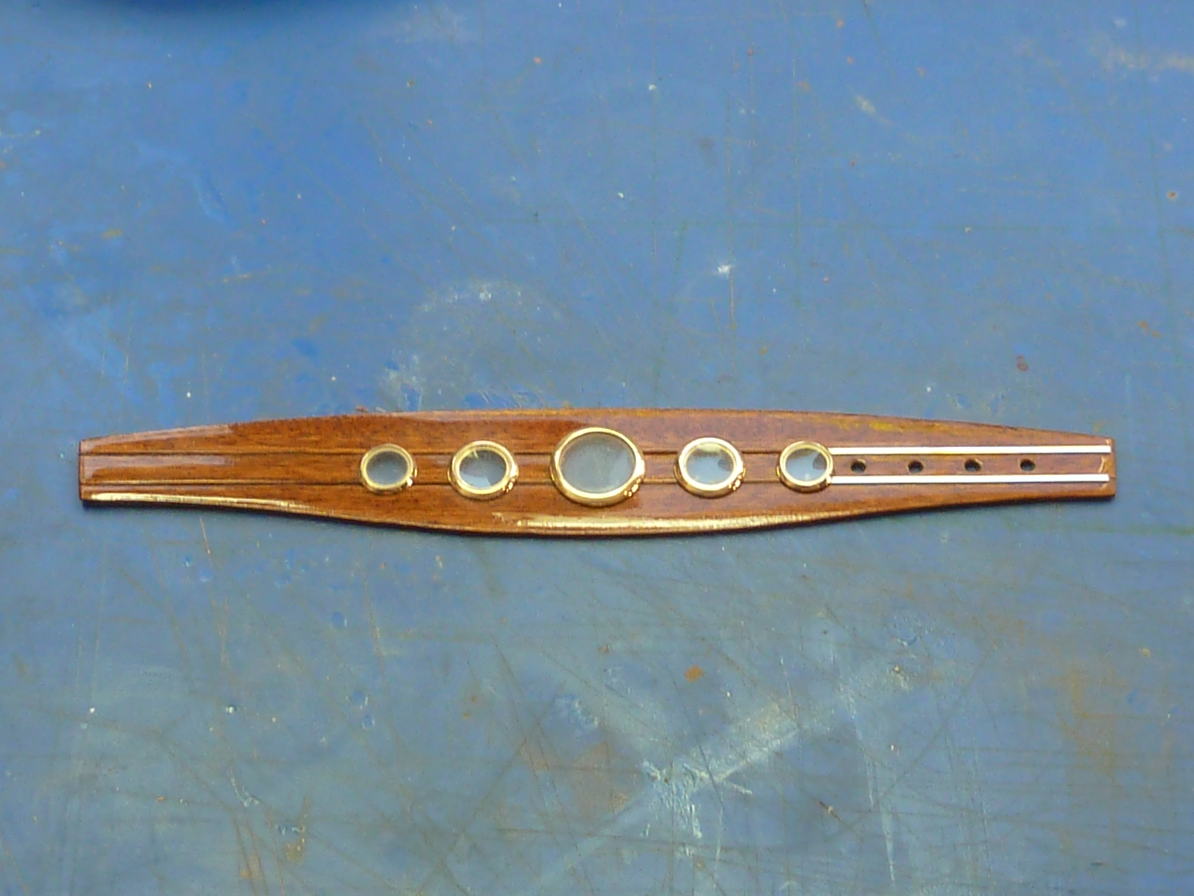
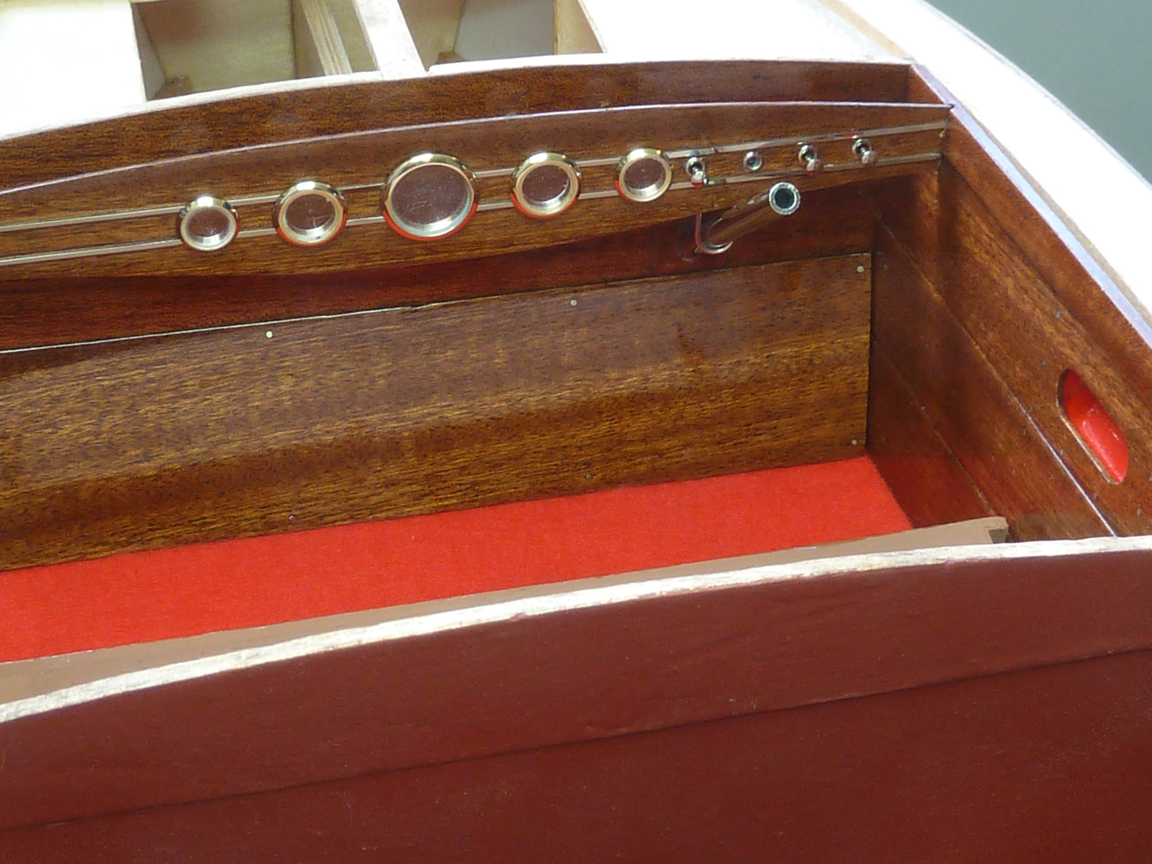
The dashboard also has some chrome trim strips across it. I decided to simulate those with 1mm stainless steel rod filed flat almost flush with the surface of the dash.
A prototype was made with the rod partially recessed into the panel and then filed flat and polished, just to prove the concept.
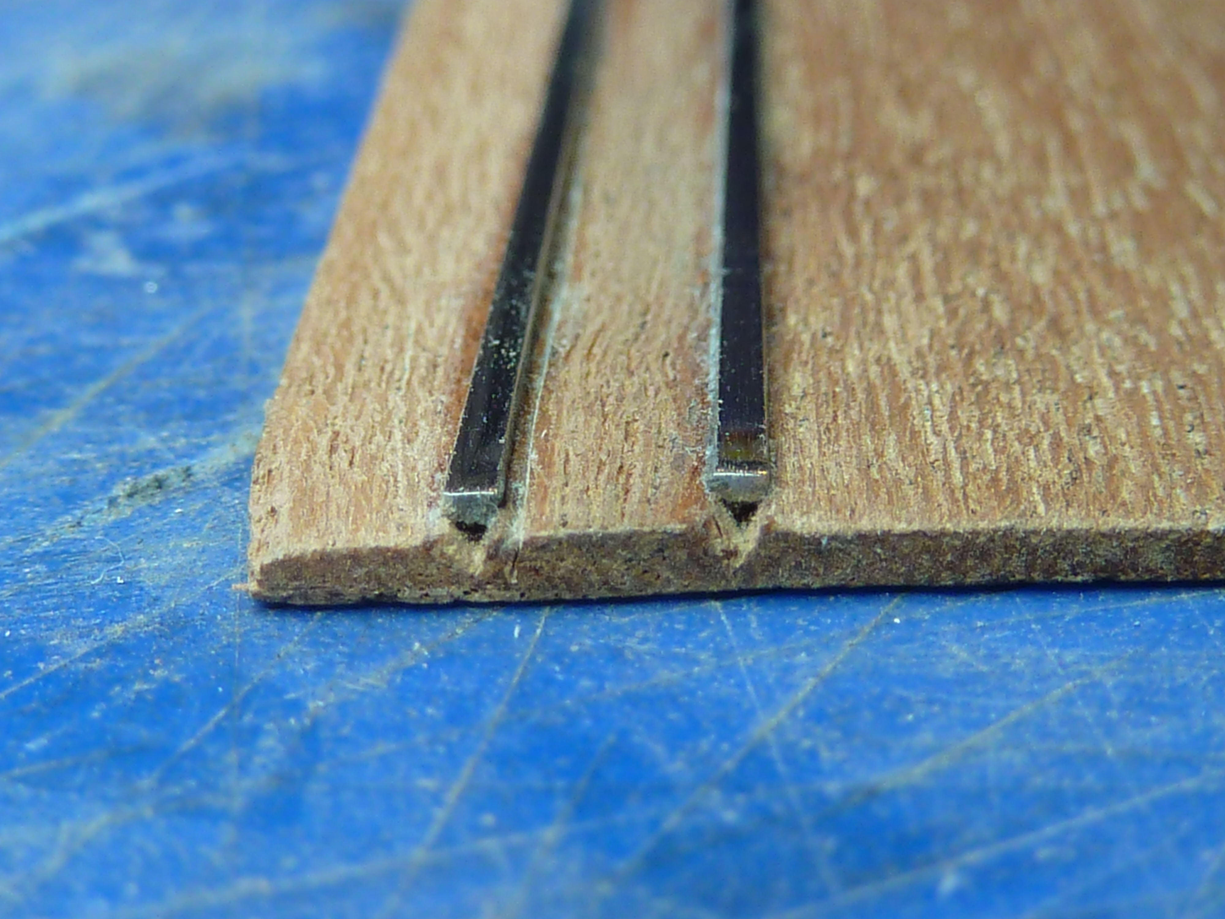
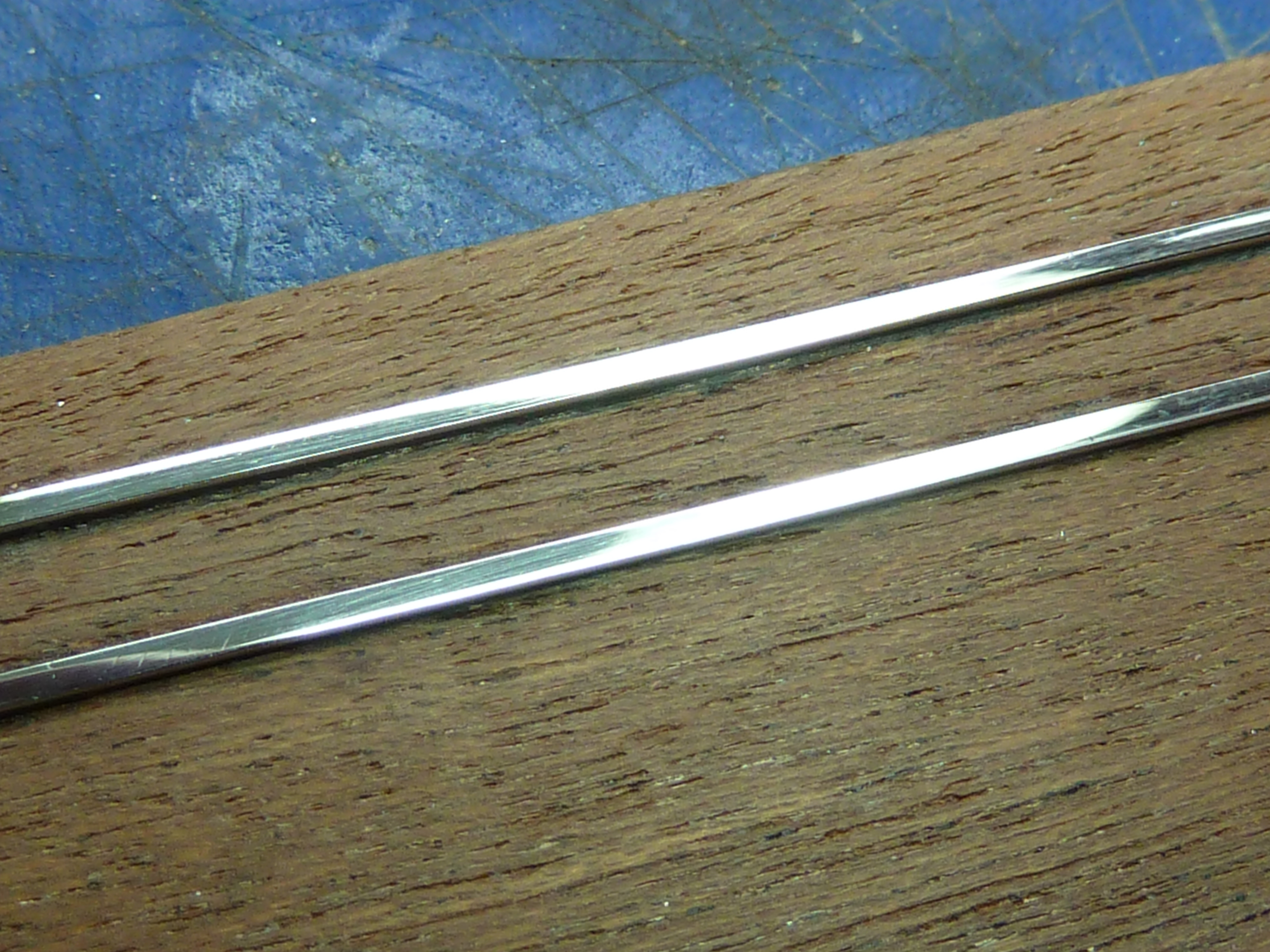
As it was, the prototype also proved useful afterwards for holding the rest of the steel rod while it was filed and polished, prior to it being cut and glued to the kit’s dash. The grooves in the dash for the rod can be seen in the pic with the portholes above.
Having sorted the instrument housings the next thing was the actual dial faces.
To make them I drew up some dials in CAD based on pictures from the net. Initially I did everything to scale, but found that when they were printed out the numerals were almost invisible, so I artificially increased their size for a better appearance. After considerable faffing about I came up with this print out.
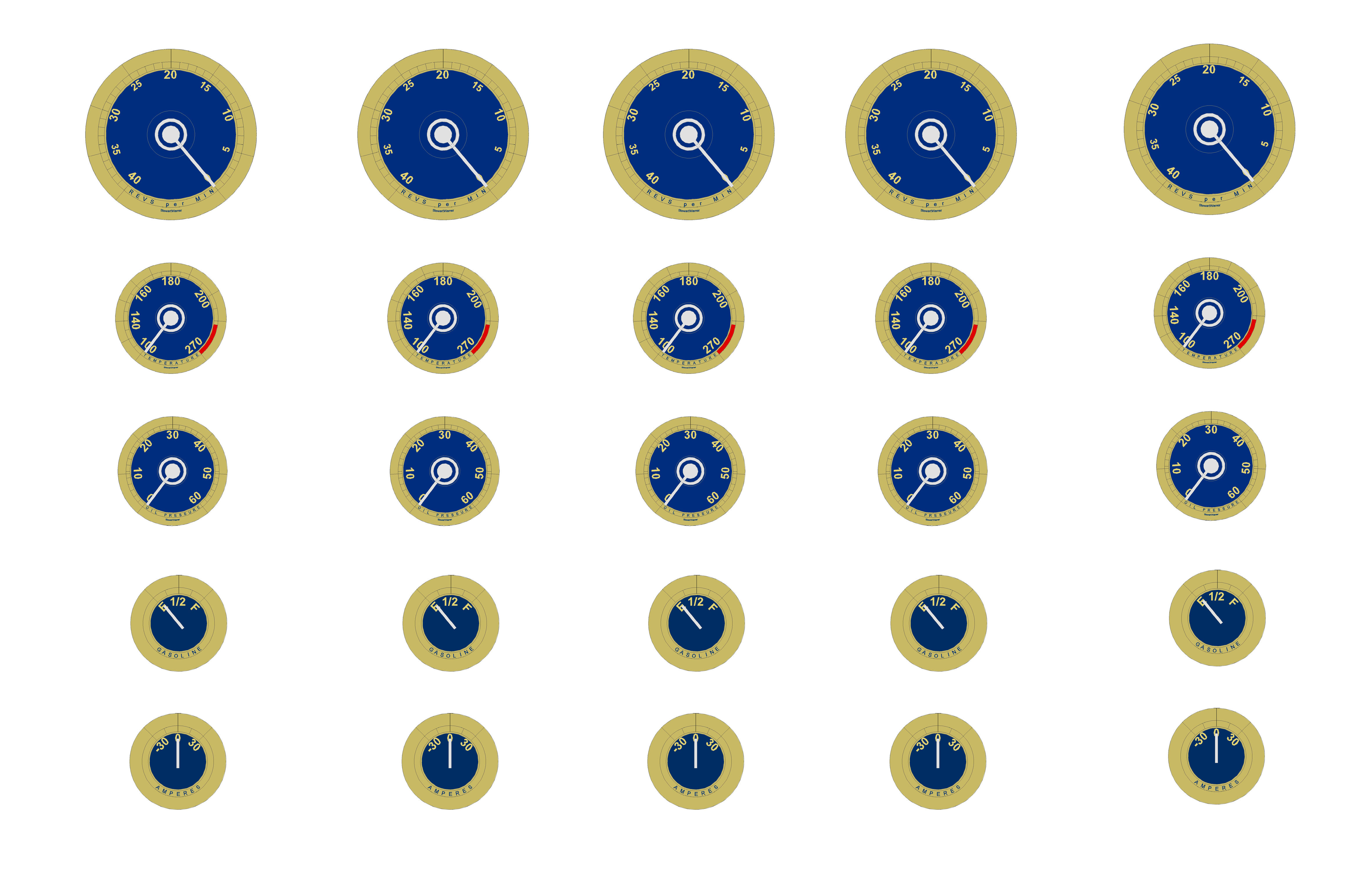
These were printed out on high quality photo paper and, after gluing the portholes in the dash and filing their backs flush, glued to the rear of the dash. I was pleased with the result, though the overlarge brass bezels still grate a little.
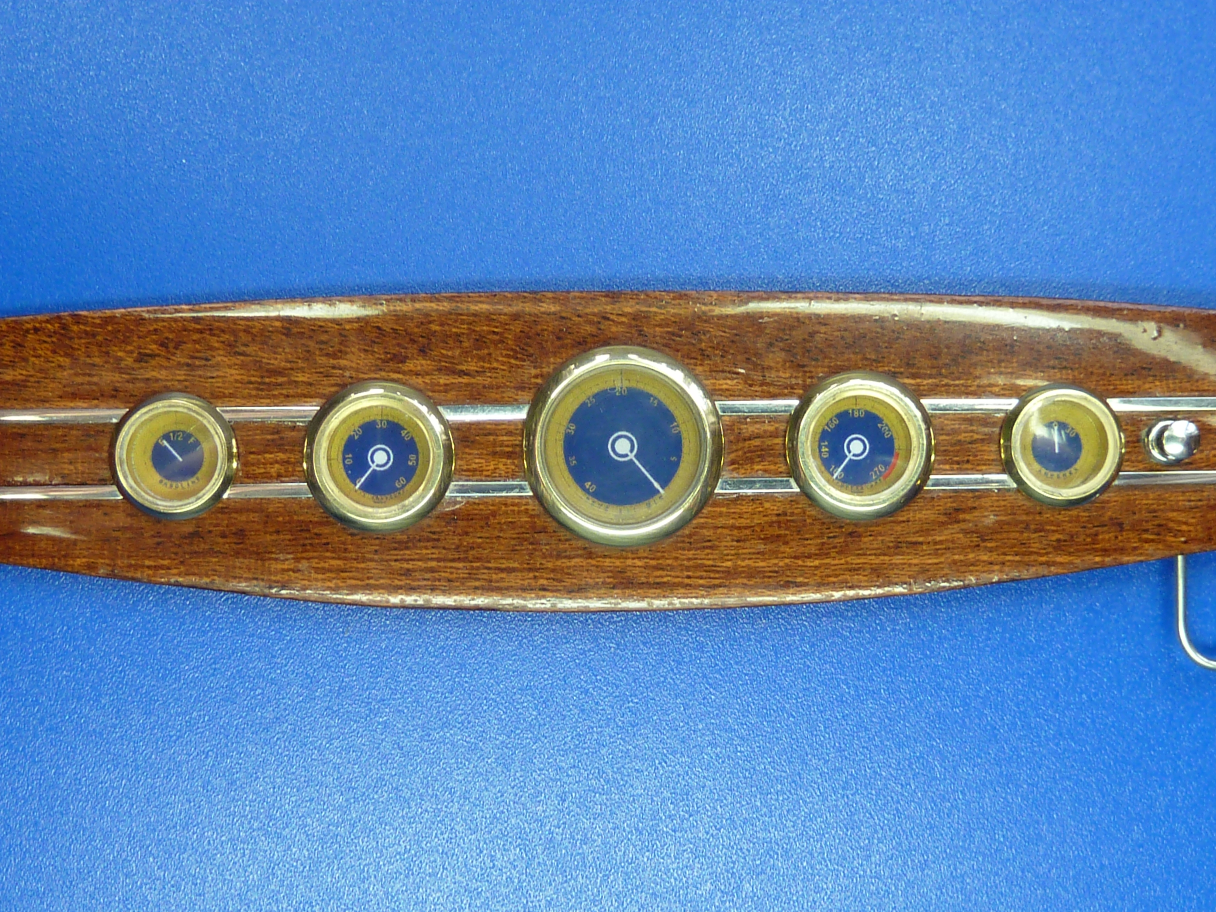
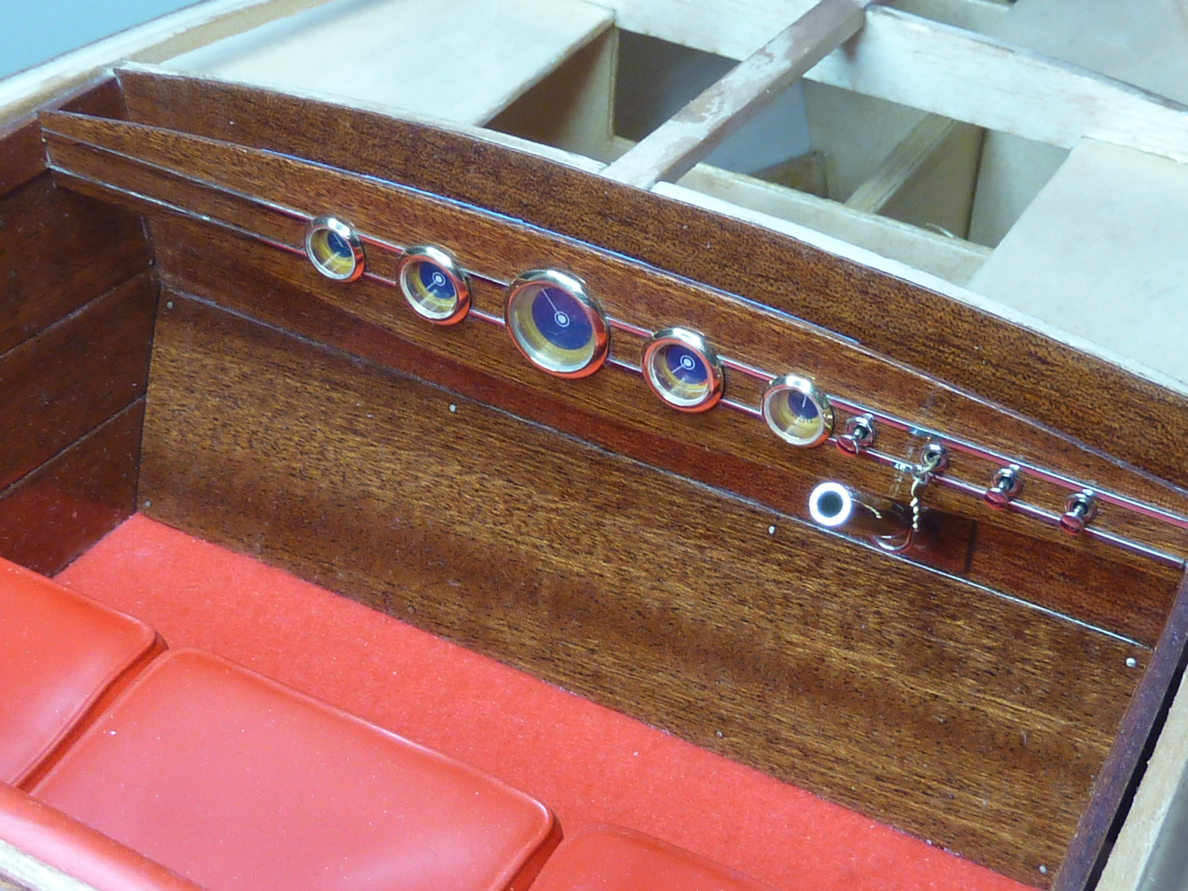
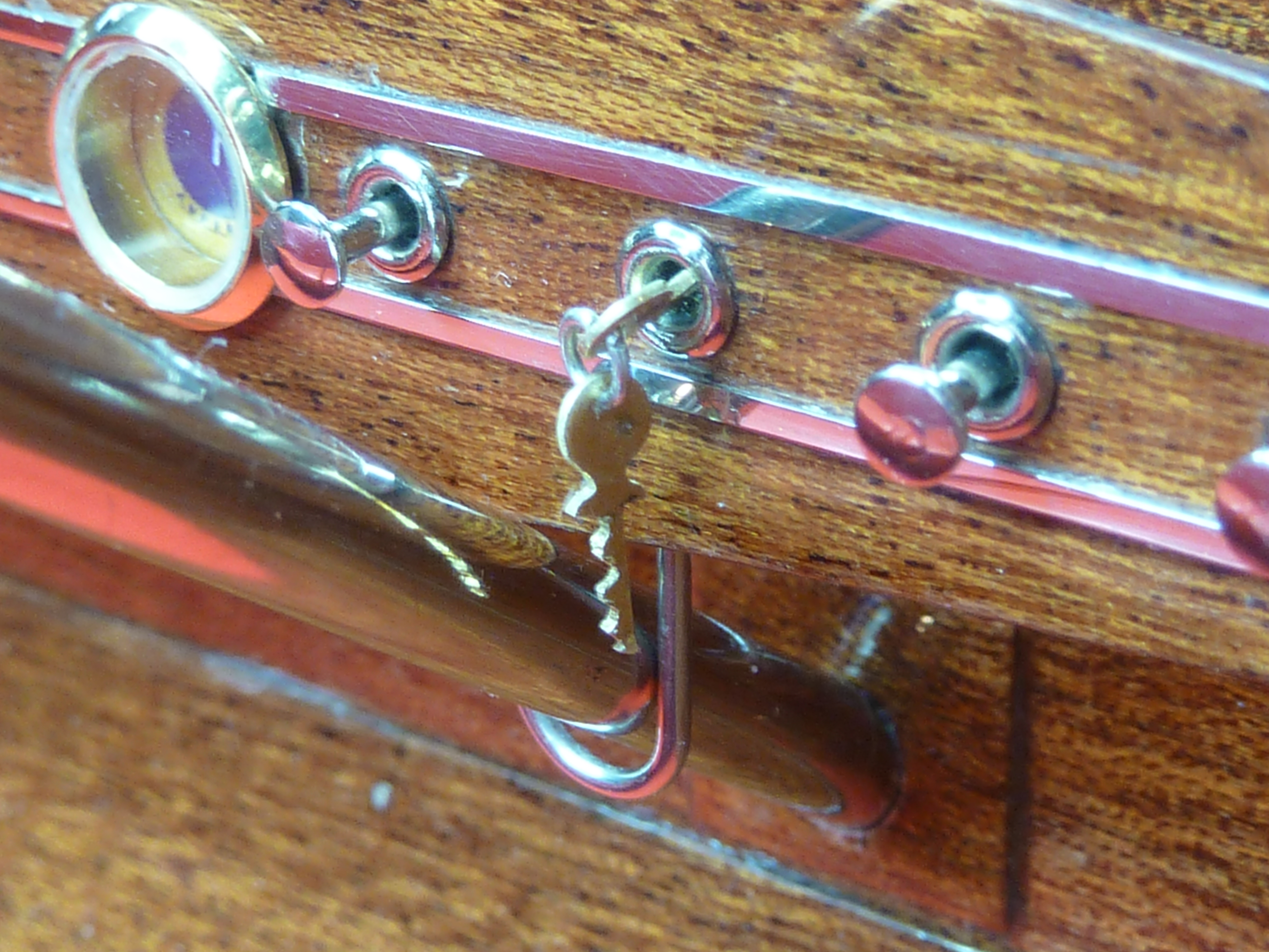
A final bit of fun was to replace one of the bank of switches provided in the kit with a set of ignition keys as I’d seen in some of the real boats. They were just filed from some sheet brass that I had to hand.
That’s it for this update. The next time we get on to planking the hull and varnishing it.

Hi, I was just checking your description of the building of this wonderfull ship. Recently I took over similar kit from a friend. Unfortunately a part of the description is missing. It is called building instructions for Chris Craft. Are you able to share those with me? Would be very helpfull.
Thanks
Bart
LikeLike
I can pass on the instructions, but not the full size drawings. There are 2 versions of this kit available though. One with an expanded PVC covered hull and one with the more traditional wood strip hull. I have the first version. Do you?
Let me have your email address and I’ll send you a Dropbox link to the PDFs.
LikeLike
Love the build, can you send me a copy of the plans? Bought a used kit that did t include the directions . Thanks!
LikeLike
Here is a link to the assembly instructions that I have. I can’t provide the full size plans as I am unable to copy them.
https://www.dropbox.com/sh/pkwba1b2ek1woki/AAACxykyYhx8D2Qhwa3G9-vha?dl=0
LikeLike
Hi, i was wondering if the first page of the PDF instructions true to scale or is it just so the drawings can fit on the paper
LikeLike
I read with great interest your Barrel Back building part 1 . . . I was wondering where I could find part 2 as it doesn’t seem to be in the same place. Can you provide some guidance? Many thanks!
LikeLike
It’s the next post along. You can either click the ‘next post’ button at the end of Part 1, or go direct with this link. https://mbiqmodels.com/2018/01/03/chris-craft-19ft-1940-barrel-back-dumas-18-part-2/
I still haven’t actually completed the model as it was only ever a test piece for another boat I’m building “Miss Severn” which is also covered on here. However, everything is on pause at the moment because I’ve had a relapse of my illness and can’t get to the modelling table at the moment.
LikeLike