
Having finished the cockpit area of the fuselage I couldn’t resist fitting the aluminium panels to complete the picture. These are quite nicely made by Hasegawa but could be improved in some respects. The characteristic oval access panel behind the engine is simply denoted by a stamped line in the panel and the line isn’t all that even to be honest. However, I didn’t think it was bad enough to warrant making yet more parts from scratch and I think there would have been problems matching the finish with the engine nacelle too, so I used it as is.
The panels fitted well on my model and with care it all went together with virtually no gaps. I started by temporarily fixing the nacelle in place and using that as a reference to ensure everything mated up
Once all the panels were in place the windscreen was fixed in position and the Aldis sight. I also couldn’t resist temporarily installing the engine and prop just to see how it looked.
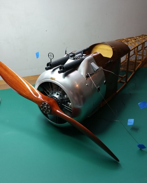
One important thing to note here is that the aluminium side panels were only held in place temporarily for the photo. They can’t be fitted permanently until after the undercarriage has been installed as they cover the upper mounting point at the front.
At the other end of the fuselage I has also previously installed the tailskid. The description of this is a bit out of sequence and should’ve been in an earlier posting, as it was done before the rigging was installed, but I forgot about it…
The tail skid is sprung in the same manner as the real thing using bungee cord.
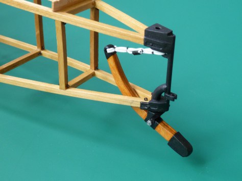
The instructions tell you to loop it around twice and then bind it with thread at 4 points. In order to make the operation easy I did all the looping and then locked the two free ends together with CA glue. Then I bound the join with black thread to give the impression of some sort of splicing having gone on. The binding thread was also given a dab of thin CA to ensure it didn’t come apart. Only after this did I put the 4 bindings on that you can see above.
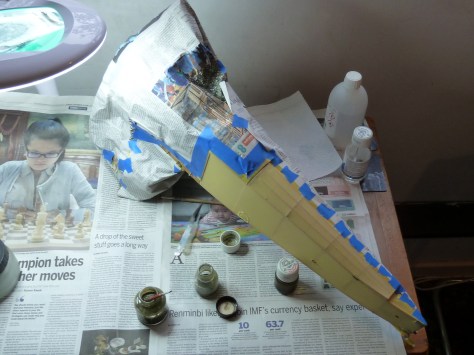
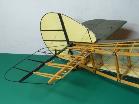
Next up was the installation of the main undercarriage. The aerofoil section of the undercarriage is made up of a number of part-machined sections of wood that are fixed to a polystyrene chassis which carries the pivoted undercarriage axels. The latter I had assembled and airbrushed earlier.
Once the aerofoil section has been assembled it is necessary to sand it to the correct profile. The end plates which attach to the polystyrene chassis provide a reference for this. The job is messy but relatively simple. Unless of course you drop the thing and knock a big chunk out of the trailing edge during the process, like I did. After cutting out the damaged section, letting in a new piece and sanding it all smooth again all was well. Luckily the repair was at a location that was due to be painted anyway, so it would ultimately be invisible.

You can just see the damaged trailing edge in the above picture.
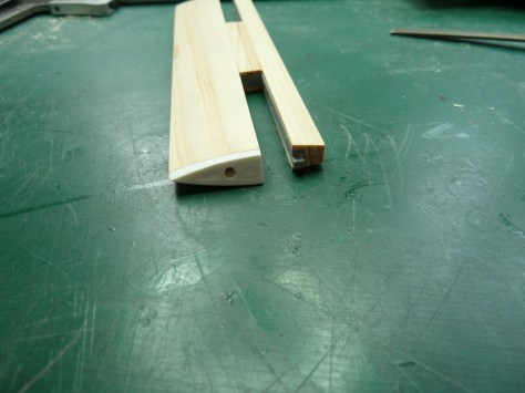
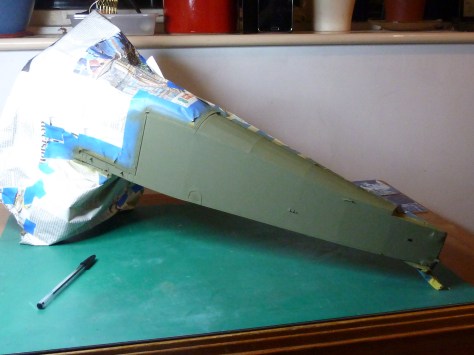
And here it is following the repair. The photo also the profiled aft section and the raw unprofiled leading edge. There is another white end piece to go on at the leading edge which gives you the profile you need to achieve.
In keeping with the half covered, half skeleton finish of the aircraft the uprights on one side of the undercarriage were finished with woodstain and varnish like the interplane struts while the other side were finished in ‘PC10’. One thing I did find helpful was to fit the lower ends of the cross-bracing wires to the struts before they were glued onto the centre section. It made getting the anchor points close to the junction of the two parts much easier.
Once complete the whole assembly was then installed on the fuselage. This is the first time you need to install the wire bracing provided in the kit and I was concerned it might be difficult to fit with the correct tension, but it was actually no problem and went well. Then it was a quick job to fit the wheels made earlier, and suddenly the model was beginning to look like a Camel.

At this point I couldn’t resist a trial of the fin assembly in place.

The little blue tags you can see in the picture are the ends of the various control wires which were annotated as per the instructions.
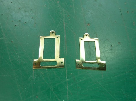
The last step in the build process prior covering and painting was to add a load of little brackets to the fuselage joins and wing rigging points. As I’ve mentioned before, I’ve struggled to find a paint that adheres to brass as well as I’d like so I thought I’d try something a little different with these brackets. I‘d read about a treatment process using a saturated solution of ammonia and copper carbonate which gave brass a lovely tough black finish if the parts were immersed in it for an couple of hours, though at the expense of making the brass more brittle.
I thought I’d give it a go and ordered up the necessary chemicals off the net. Rather than risk messing things up I tried a few test pieces of brass tube and sheet off-cuts that I had lying around. Sure enough, after 2 hours in the solution the bits were a deep bluish black and not so brittle that I couldn’t form them into the shapes required. So I degreased all the kit parts and dropped them in the solution for a couple of hours…
Now, I don’t know what went wrong (I’m a physicist not an alchemist), perhaps the brass alloy was a slightly different composition to my test pieces, but to say the parts came out brittle would be a vast understatement. They cracked if you looked at them harshly. Even just decanting off the treatment solution caused the parts to break up leaving me with a pile of nicely stained fragments…
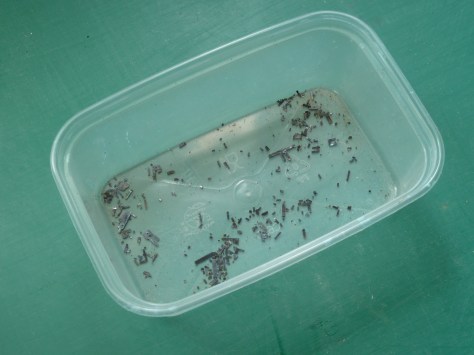
Intemperate words were used at this point. The sort usually reserved for WordPress’ awful editor which is used to compile these posts.
After a small cry in a dark corner I set to making all of the little brackets again. By hand. Alone…


 So that filled up about a week of my model making life. When the parts were made they were fitted and painted in situ. Learn from this kids. Don’t try to be a smart Alec!
With the basic assembly of the fuselage complete it was time to cover and paint.
I had thought that the covering might be awkward but it was surprisingly easy, due in no small part to how easy the Solartex is to work with. One small deviation from the kit was the inclusion of a guide pipe on the lower elevator control wire run where it exits through the fuselage side. This has been omitted on the kit but is necessary if you are covering it.
The bracket can be seen in the Shuttleworth photo I referred to earlier.

The bracket in question is on the fuselage upright to the left of the centre of the picture. The control cable that runs through is stored in a coil hanging on the side rigging. A similar one for the top cable to the elevator is shown at the top of the fuselage upright on the right of the picture. A representation of this one is incorporated into the model, but it isn’t that marvellous to be honest and I upgraded mine to improve it a little.
With all the bracketry in place and the covering on it was time to mask and paint.
The fuselage roundels and serial number panel were once again sprayed on using simple masks made from Frisk sheet.


The serial number was made as a transfer in the same manner as the Sopwith logo on the fin. A bit of research revealed that there was no standard font for the numbers at this stage and the various manufacturers used their own variants. That being the case I surfed the net for one that matched as closely as possible to the one used by Sopwith. The font I settled on was Gadugi Bold which was close enough for the numbers and letters I’d be using. I’d decided to model the first Camel obtained by the RFC, N6332.

“Camel N6332 was the third production Camel of the 1st batch manufactured by Sopwith (N6330-N6379). It arrived at Dunkirk on 17th May 1917 and was transferred from the RNAS (hence the N serial prefix) to the RFC on 25th May. It flew with No. 70 Sqn from 13 June. It was shot down near Waterdamhoek by Vizefeldwebel Rudolf Franke of Jasta 8 on 17 July 1917; Lt W E Gossett was made PoW. N6332 was the fourth of Franke’s eventual 15 victories – he was later commissioned, and survived the War.”
There are also two prominent “Lift Here” stencils which can be seen in the picture. As my poor old inkjet can’t print white I opted to print the text on white decal paper with a colour matched surround that I could feather into the existing green of the fuselage. While an OK idea in principle it wasn’t a success in practise and I ended up simply painting up to the edge of the words with my PC10 mix once the decals were in place. It turned out OK in the end though. Once faffing about with roundels and decals was over everything was given a couple of coats of clear satin varnish to match the wings.
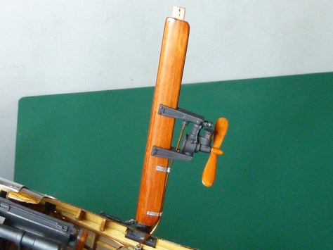
The last work on the fuselage was to install the cabane struts made earlier, fit the Rotherham Pump (used to pressurise the non-gravity fed fuel tank) and plumb it into the fuel system. The propeller on the pump is a white plastic part so I simulated a wood finish using artist’s oils. The prop was given a base coat of a dark tan colour, sealed with acrylic varnish, then it was coated with Burnt Sienna oil paint. While it was still wet a stiff brush was dragged through the oils to simulate a wood grain pattern.
To get the cabane struts at the right angles I used the centre section of the wing as a temporary jig to hold them in place while the glue cured.
I also couldn’t resist fitting the tailplane and fin which took a matter of moments. Suddenly the fuselage was looking pretty good.


That pretty much completed the fuselage with the exception of the seat and the padding around the coaming, both of which became a bit involved due to the age of the kit and some of the parts becoming brittle. I’ll cover those in my next installment.

Looking good!
LikeLike
Your patience astounds me. I would have given up or at best ordered the replacement parts that disintegrated. I’m sure you have already said this but what scale is the model? The detail is incredible!
LikeLiked by 1 person
It’s pretty large. 1:8 scale. The wingspan is 107 cm or 42″.
The kit has been out of production for quite sometime now. So Hasegawa no longer stock any of the parts. If they break or are missing you are on your own.
LikeLiked by 1 person
Wow that’s a pretty impressive size. You clearly have some stunning modelling and engineering skills!
LikeLike
After reading ALL of these posts, it doesn’t sound to me like they have much appreciation or respect for their loyal customers. For the original MSRP, I would have expected something somewhat more faithful to the original design.
I’ve already got a kit on the way, but there will be no more Hasegawa products in my future.
LikeLiked by 1 person
I’m surprised they’ve replicated many of the faults in their new 1/16 scale Camel, but on the whole Hasegawa’s kits are good. I’m a fan of their stuff TBH.
LikeLike
In this blog I only highlight where the kit deviates from the real aircraft, which is a bit unfair to Hasegawa because the majority of the kit is extremely good and the final model is exceptional. I’d recommend it to anyone, but this is a blog of exceptions, so I’m only highlighting where I’ve found the model deficient.
LikeLike
If it weren’t for stumbling across this blog, I would have never had the nerve to break the plastic wrapper on the kit box!
As it is, I’m forging ahead with some degree of confidence in my ability to follow YOUR instructions and suggestions while muddling through my own building process.
Thank you so much for all the extra time and effort that you expended in bringing this fantastic build to the net.
Best wishes,
JP
LikeLiked by 1 person