
As I mentioned at the end of my last post, I’ve been taking a small break from the boat building to assemble Hasegawa’s white metal version of their 1:8 scale Clerget 9B engine.

The kit is quite rare now and definitely a collector’s item. It felt slightly naughty actually building something this collectable, but that is what Hasegawa made them for. I’m building this one to represent an engine from a Sopwith Camel.
It would appear that Hasegawa didn’t lavish much development money on the kit. The white metal castings have clearly been made directly from one of the injection moulded kit’s parts. You can even see the ejection pin marks which were carried over on the inlet tubes. The castings themselves are however quite good, but very soft. There are some unexpected errors in the kit though, which I’ll deal with as they come up.
I had planned to make this build log in the order I’ve been making the kit, but that has been a bit scattered as I’ve flipped from one section to another while I’ve waited for various raw materials to be delivered.
So to impose some sort of order on an undisciplined mess I’lI try and group things into logical sections instead.
To begin with, I’ll start with the mounting stand and the ancillaries at the rear of the engine.
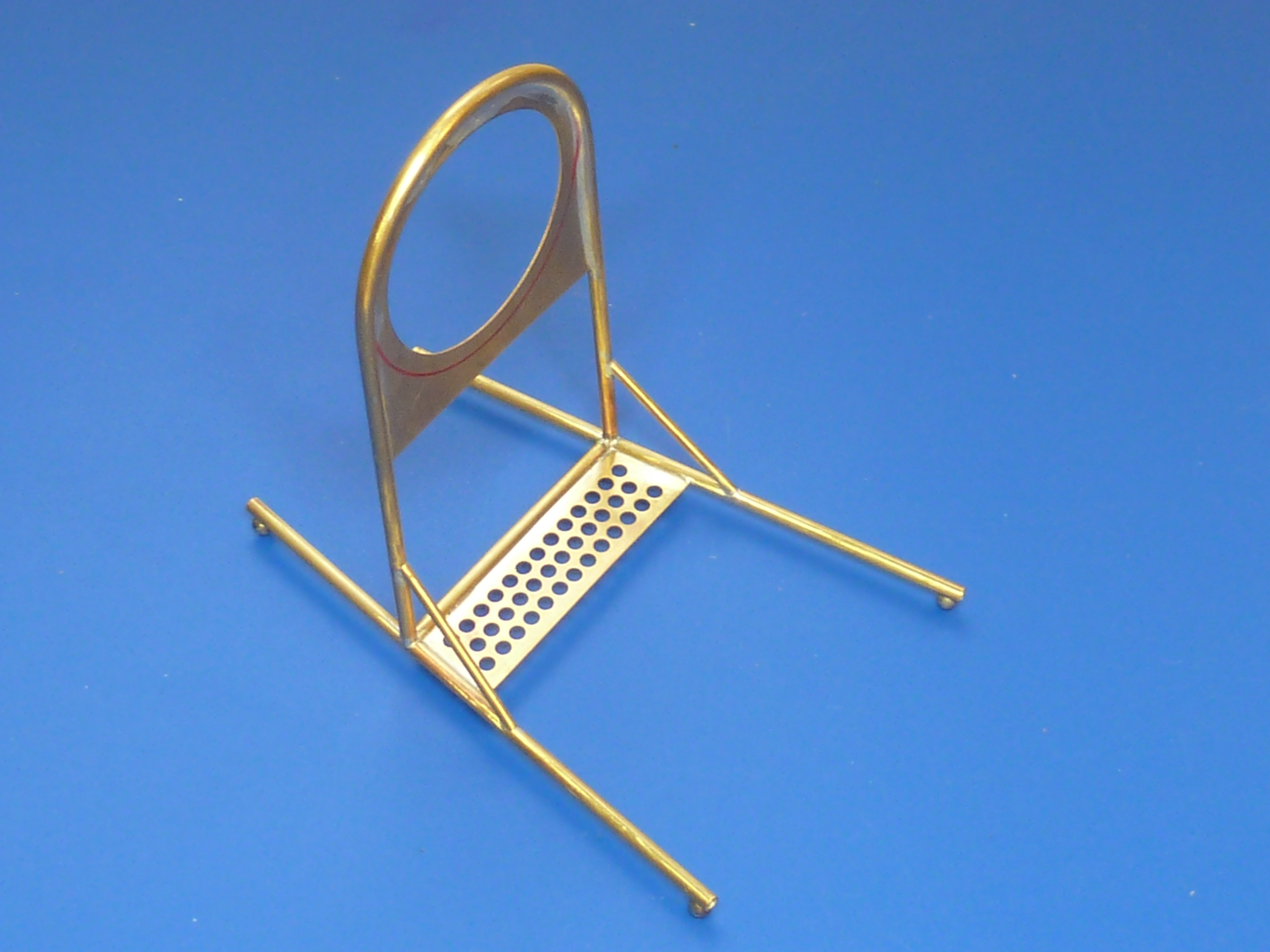
The kit has a very simple stand made from bent chrome wire. There is no mounting plate or ancillaries at all, unlike the injection moulded variant. The model stops at the gears at the rear of the engine. To give you some idea of the changes in store, the picture below shows the kit’s stand, sans ancillaries, next to my scratch-built version.

I based my engine stand design on the one that comes with the injection moulded kit, but made from brass tube and sheet rather than plastic.


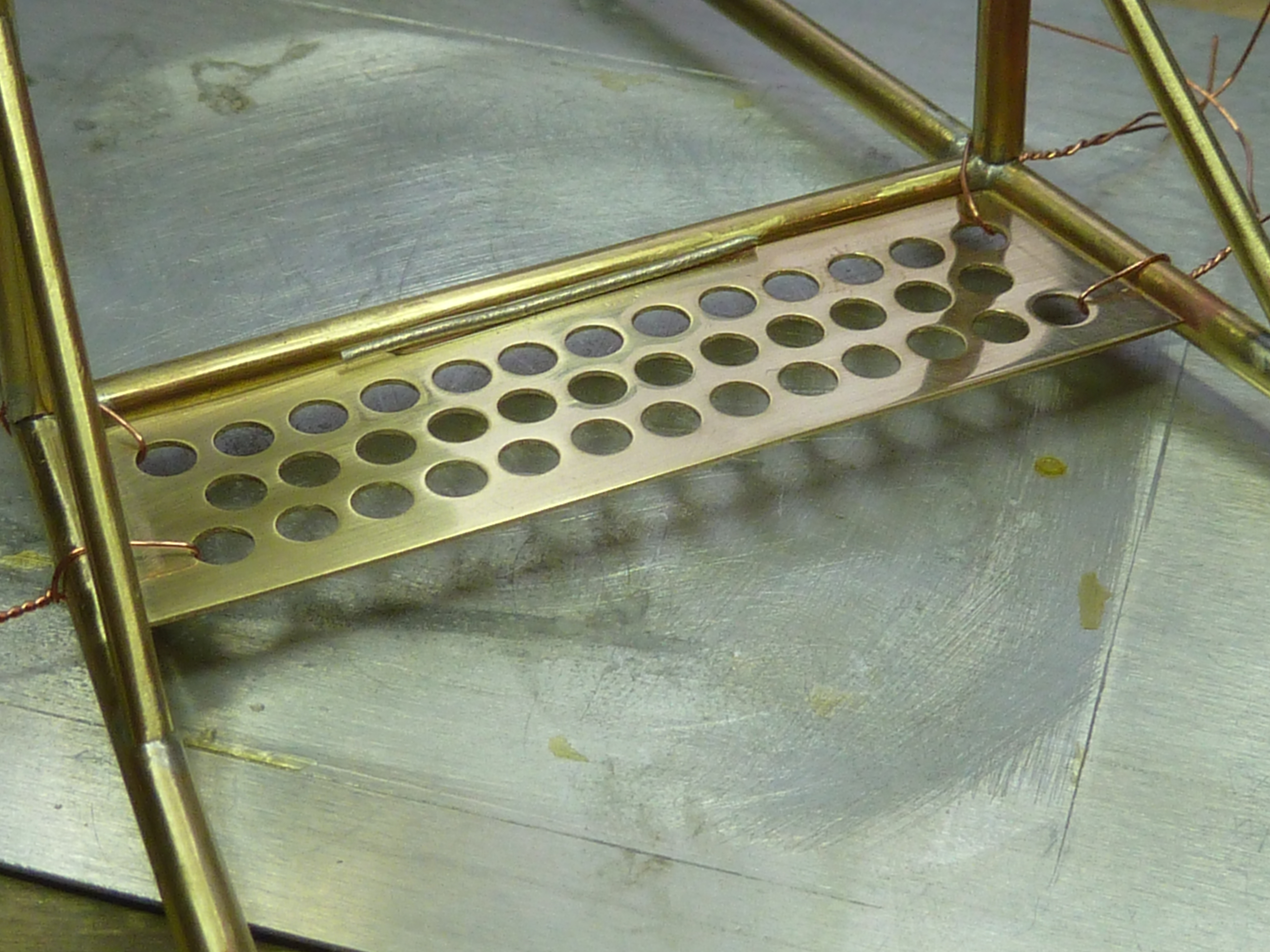
I use a chef’s torch for most of my soldering by the way.

Having made the stand I commenced the scratch-build of the ancillaries. Firstly the magnetos.
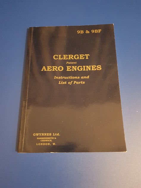
I had intended to base my work on that of the injection moulded kit, but a bit of research indicated that that is actually quite inaccurate. In fact it’s nothing like the real thing. So my design has been based on various museum photos, CAD renderings, M-L Magnetos’ ADS/17 handbook and the reprinted (2001) “Clerget Aero Engines: Instructions and List of Parts”.
The magnetos were made from a mix of steel and brass. Steel because it’s what I had in the garage that was about the right size.


Next was the castor oil pump with tacho drive. Again this was made from steel and brass, and for the same reasons.

Once it was assembled, the pump was nickel plated to give it a uniform finish.
The brass parts of both the magnetos and the oil pump were then aged using a very dilute burnishing solution…
Step forward AK Interactive’s metal burnishing fluid. This is actually intended for weathering white metal track links on tank models, but I’ve found it has lots of other uses for darkening and generally ‘ageing’ metal surfaces. Used in highly diluted form allows quite fine control of the effect obtained.

Here are the parts after being treated.

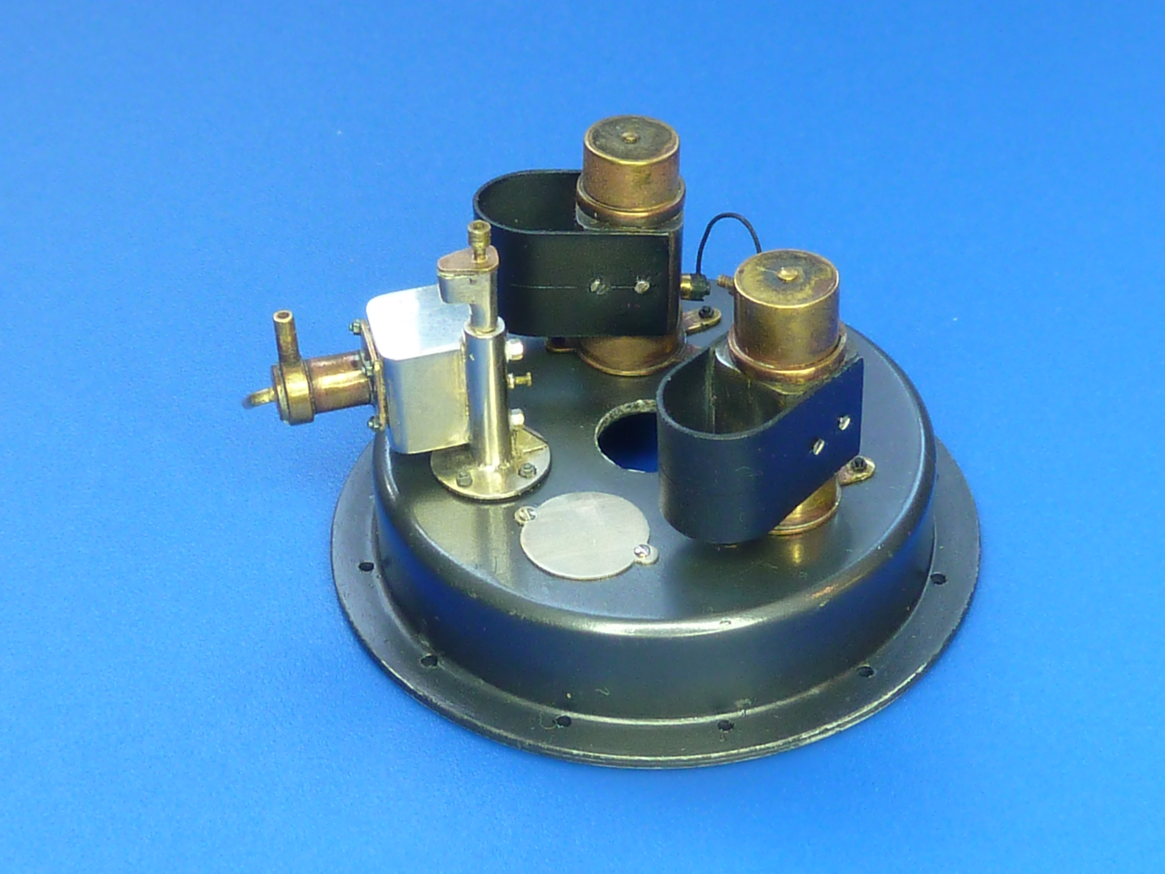
Here they are mocked up on the engine mounting plate prior to painting. The plate was made from plasticard.

The Clerget engines in the Camel didn’t have the manual cranking handle attachment, or the air pump so the mounting points of both of those were covered with blanking plates. I also made a blanking plate for the gun interrupter attachment points at the top of the engine mounting plate.
Here is everything suitable plated and aged on the painted plate. The two brass studs in the foreground are the brushes to connect the magnetos to the ignition leads.

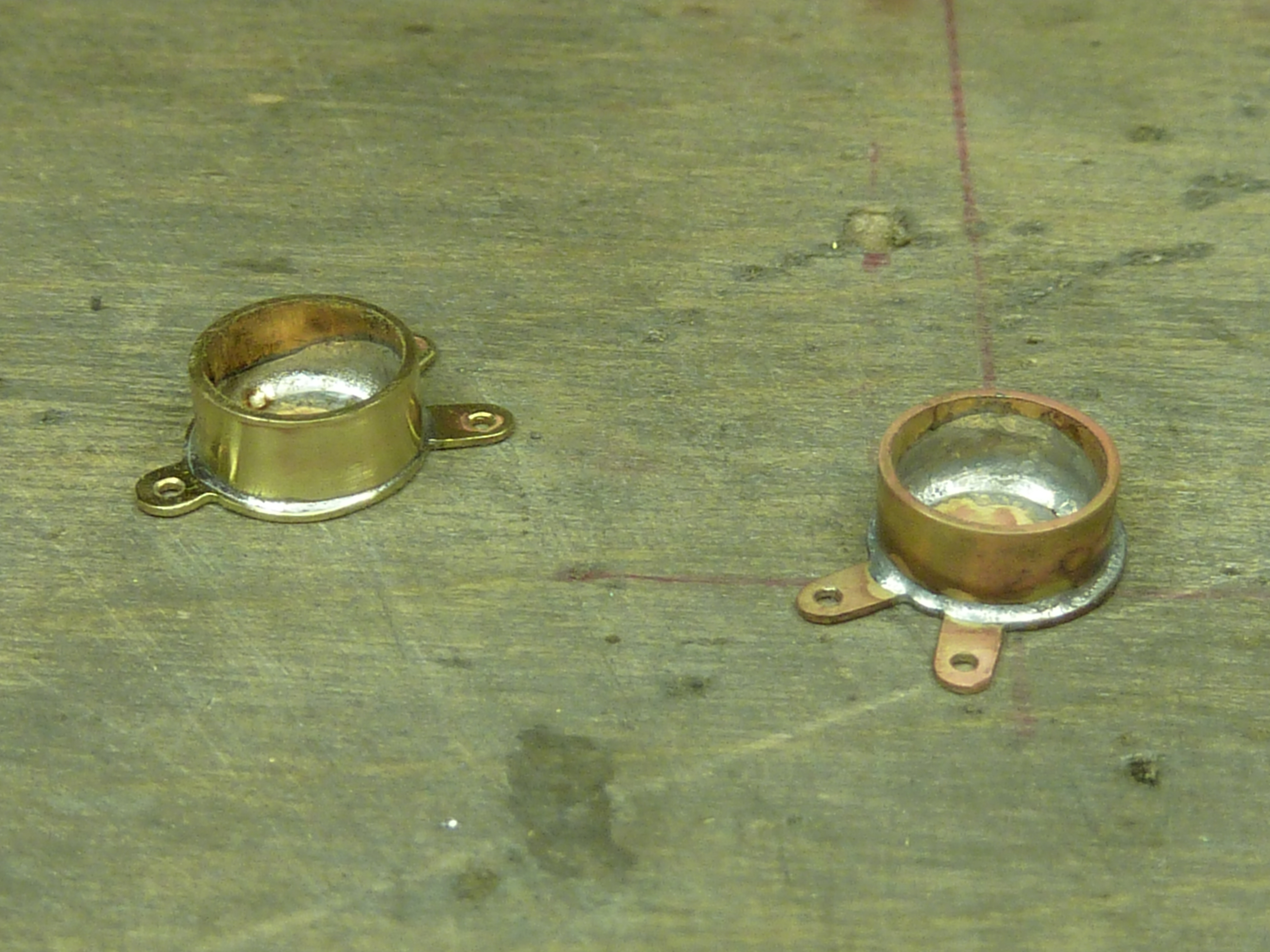
The rear mounting ring for the engine was made from brass sheet and tube. Then nickel plated and aged to look like steel.

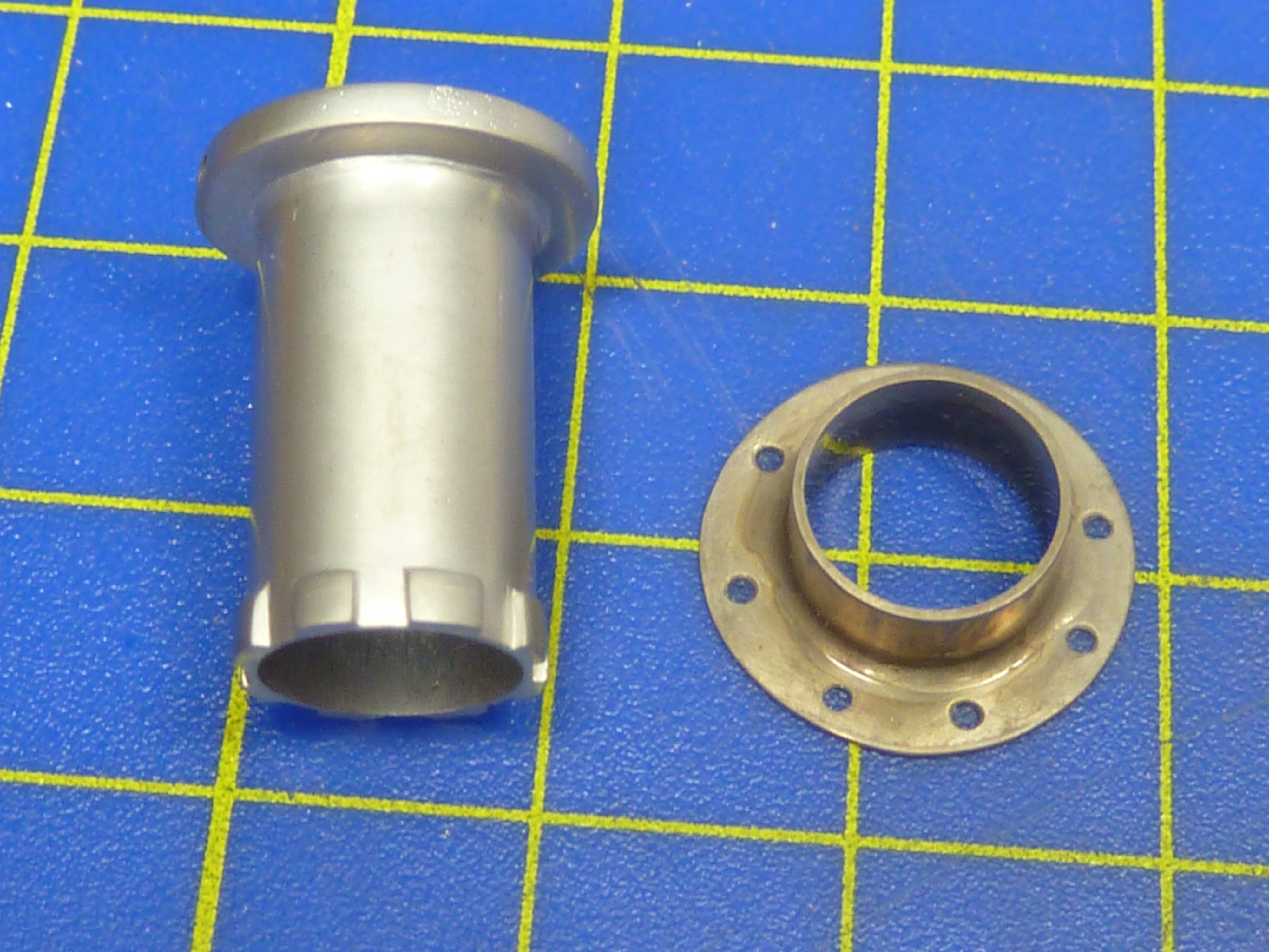
There is an unusual sleeve at the forward mounting point of the engine at the mounting plate.

To replicate this I used some concentric brass tubes of 9 and 10mm OD (wall thickness 0.45mm). I cut some castellations in the end of a section of the 10mm, then soldered them to the 9mm.
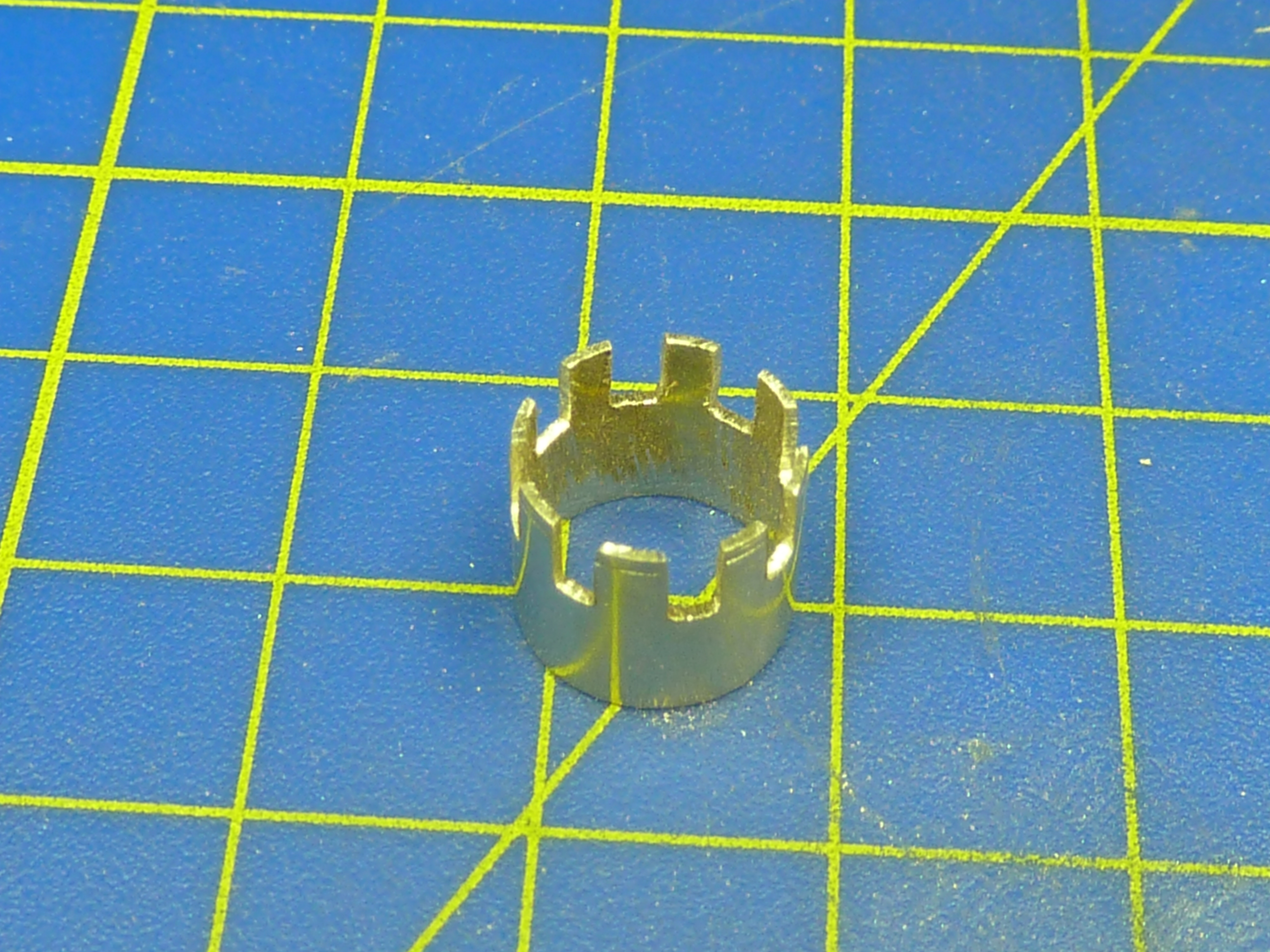
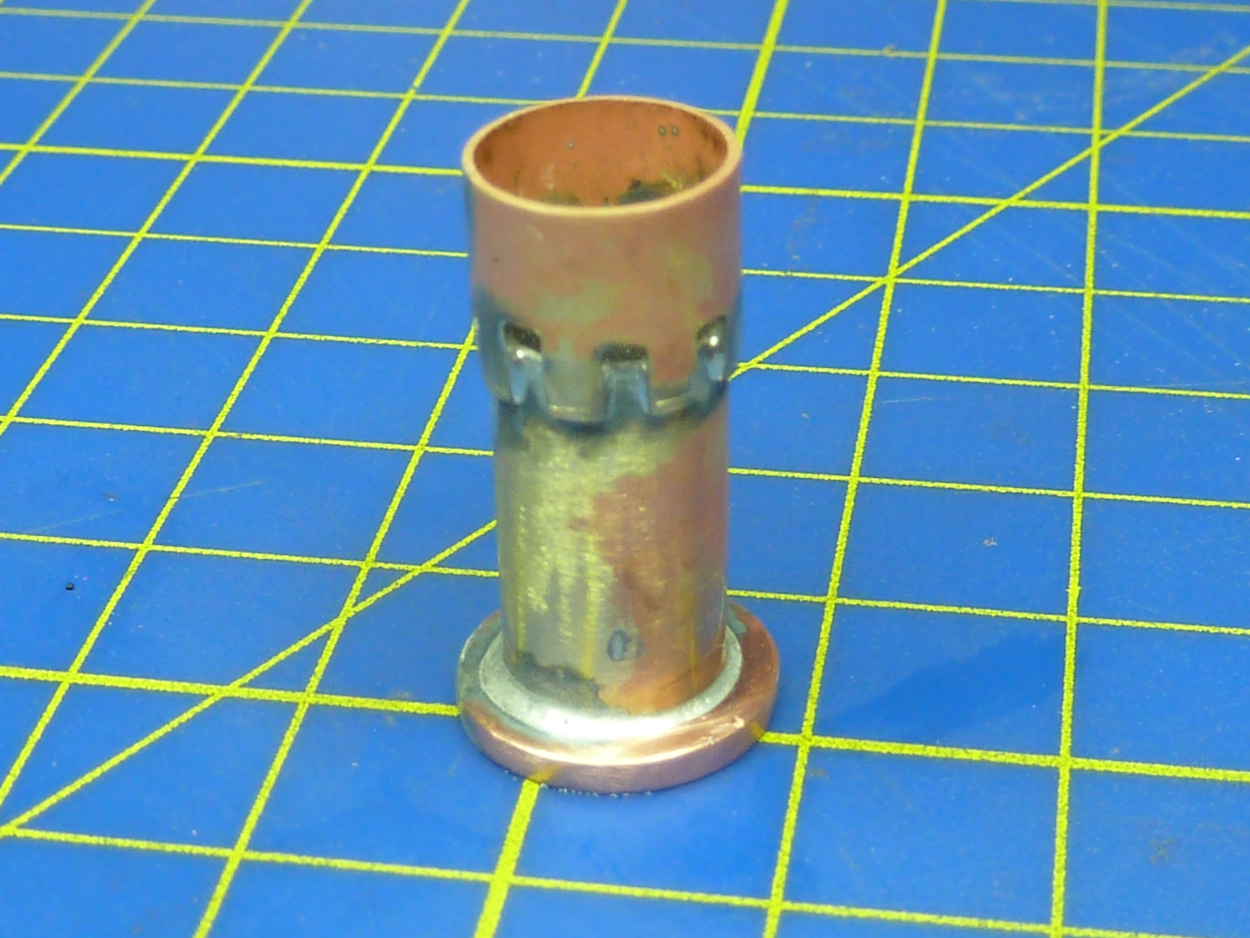

Next the unwanted section was cut off and the end filed true.
Yet again the parts were plated and aged.
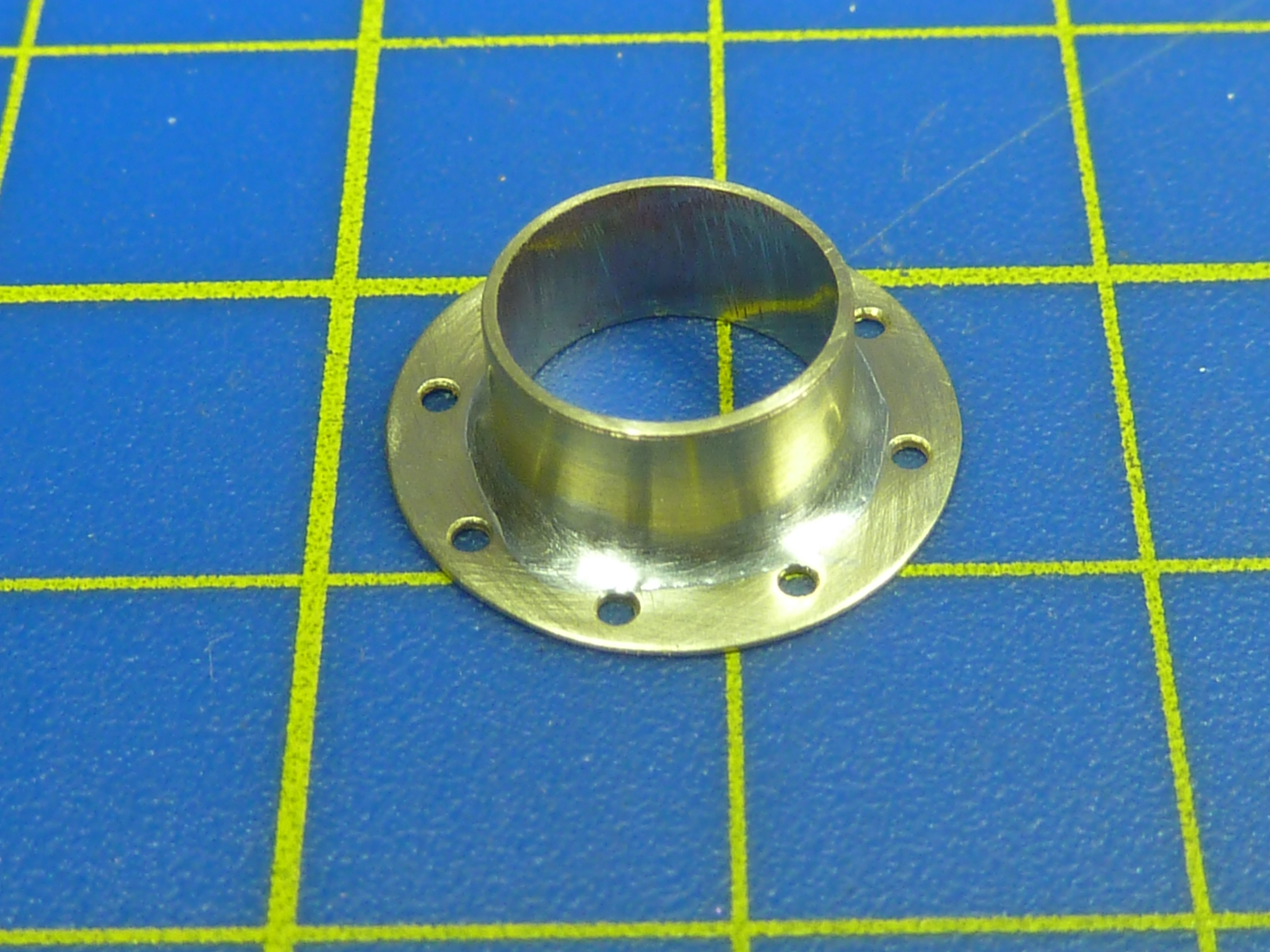
Here’s the aged rear mounting next to the freshly plated front mounting sleeve.
The final bit of the ancillary story was the carburettor and it’s inlet pipes. These are very visible in the Camel cockpits.
I started off with some 8mm copper fuel pipe, which had the benefit of fairly thick walls.

This was cut and soldered to form the basic shape.
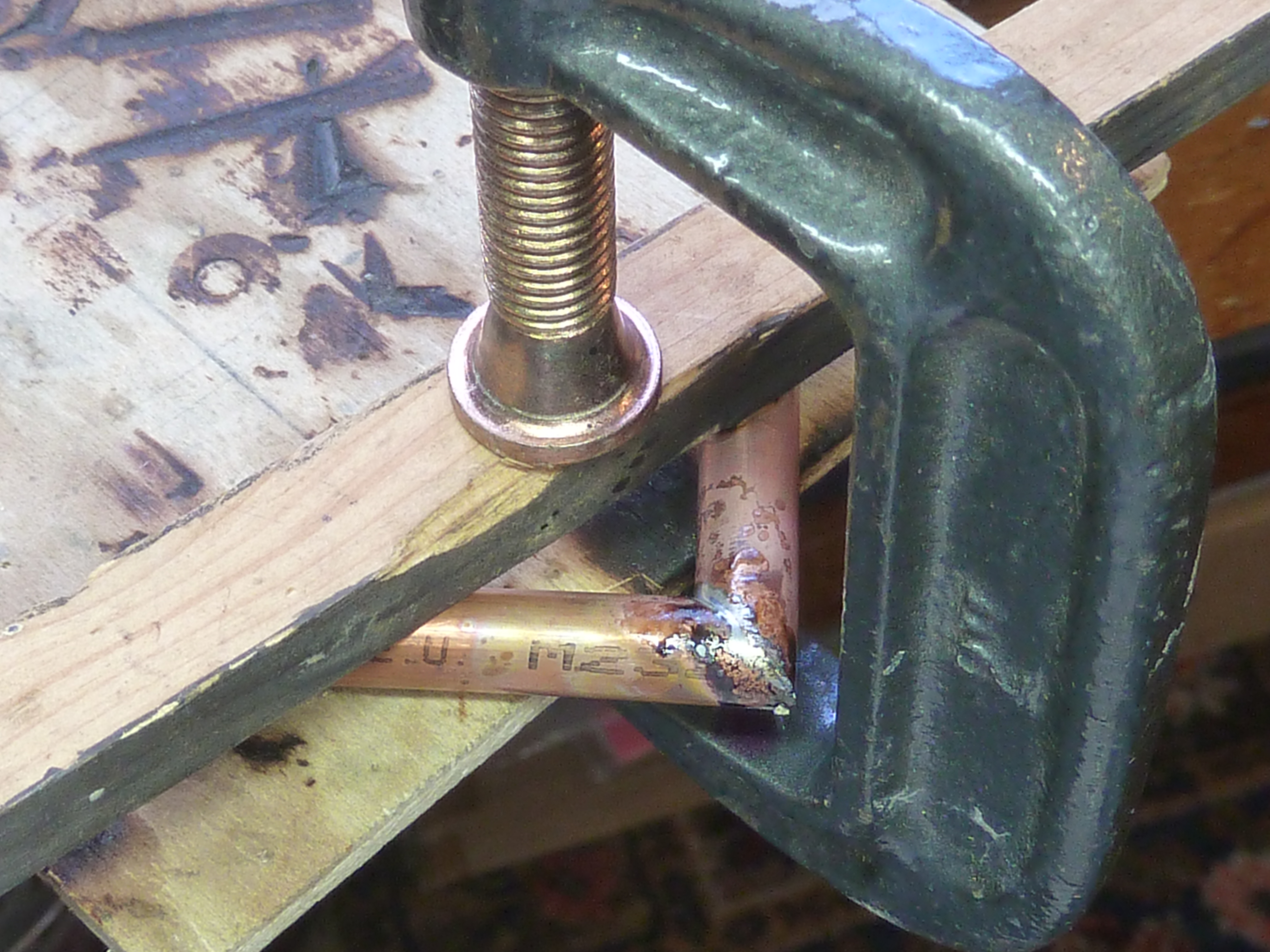
The assembly was then filed and sanded round on the corner, which is where the relatively thick walls of the fuel piping came in handy. It allowed me to get more curvature on the outer radius without breaching the wall.
The real item on the Camel appears to be an alloy casting with gentler curves than I’ve been able to obtain with the copper tube. I did have a quick go at making my own casting, but I was unable to satisfactorily bore it out so the idea got scrapped.
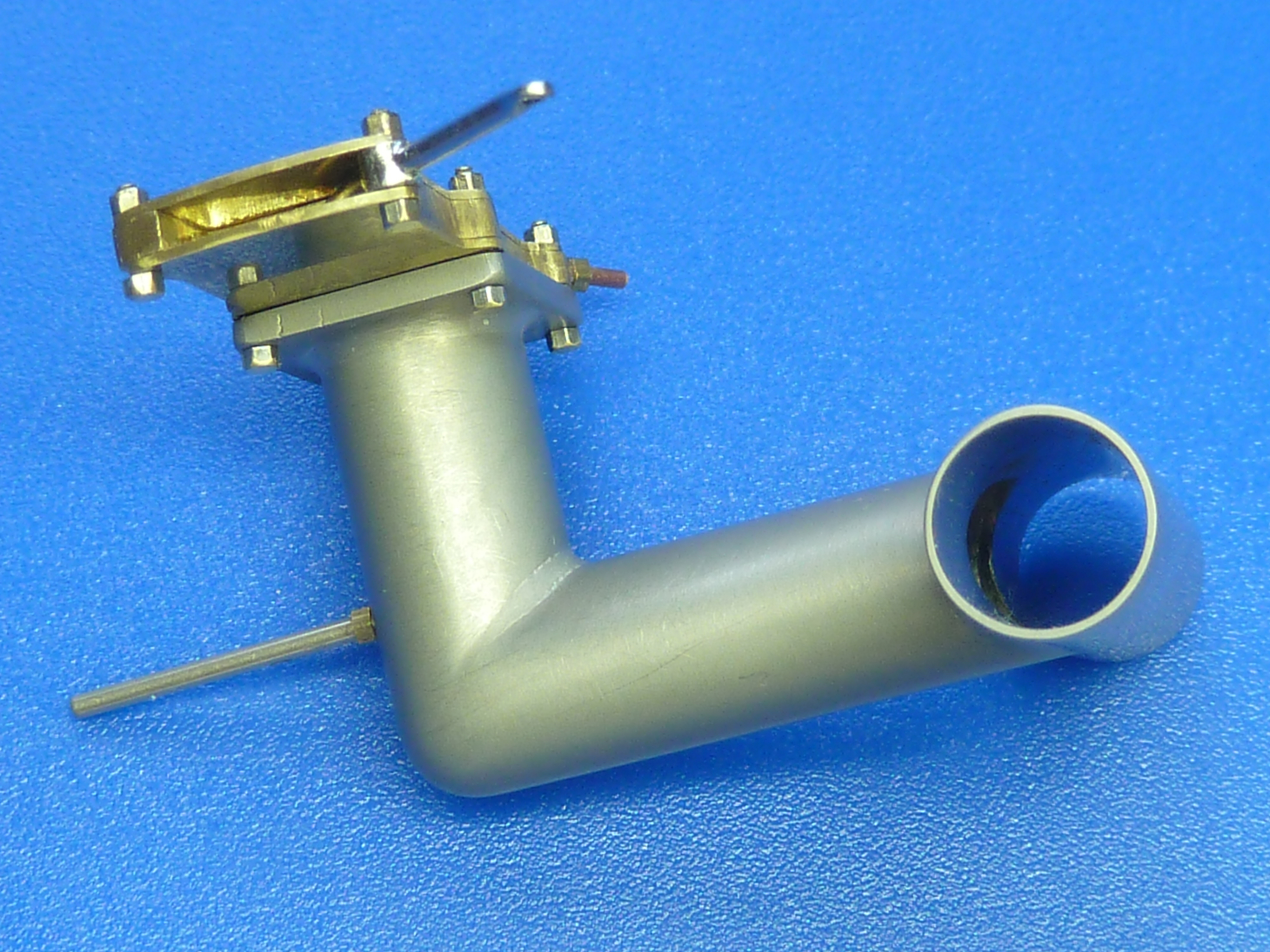
Once filed to shape a mounting flange and cross piece were added.

Having examined the finished item I wasn’t that happy with it to be honest. The cross piece was wrong and I thought I’d get away without having an internal hole where it met the down pipe. In reality it looked completely fake when you looked in the open ends so I salvaged the mounting flange and remade the assembly with the hole.
Below you can see the finished item after plating. Next to it is the carburettor which was simply cut and filed from 3 sheets brass. 2 of 0.5mm with a 1.5mm sheet sandwiched between them. The bolts hold everything together for real.

Here are all of the ancillaries finally mounted together on the engine plate. The central tube is made from plated and aged brass. All that is left is to fit some of the oil piping and the blanking plates for the hand crank and interrupter gear. They’ve been left off until I mount the whole thing in the engine mounting as they won’t fit through the gap.

Here, again, is the picture of the ancillaries temporarily mocked up in the mounting frame. Next to it is what you get in the actual kit.
It’s hard to believe I’ve scratch-built all that. It’s a bit advanced for me.
Next time I’ll get on to assembling the actual engine proper.

It’s a fabulous start! I’m Looking fired to more!
LikeLiked by 1 person
Yet Again ,Another fine example of your incredible attention for historical accuracy and detail in all your projects ,glad to see you taking on aircraft subjects once more.
LikeLike
BRILLIANT! As you know, like you I made the Camel version and the stand-alone version in plastic, but that is worlds apart. EXCELLENT, as always.
LikeLike
If there are any other people out there that produce the consistently jaw-dropping level of incredible detail that I’ve seen in every picture you’ve posted over the past several years, I’m not aware of them and they’re surely fantastically rare! And I’ve been to a LOT of museums with some Very finely executed and detailed models of similar things over the past 60+ years, Including the Smithsonian – but still…
Bravo!
LikeLiked by 1 person
Remarkable work. it’s a pleasure to read and look at your photos. Bravo.
LikeLike
Thank you.
LikeLike